HAL Id: hal-01461891
https://hal.inria.fr/hal-01461891
Submitted on 8 Feb 2017
HAL is a multi-disciplinary open access
archive for the deposit and dissemination of
sci-entific research documents, whether they are
pub-lished or not. The documents may come from
L’archive ouverte pluridisciplinaire HAL, est
destinée au dépôt et à la diffusion de documents
scientifiques de niveau recherche, publiés ou non,
émanant des établissements d’enseignement et de
Time in PLM
Yu Yan, Emilie Poirson, Fouad Bennis
To cite this version:
Yu Yan, Emilie Poirson, Fouad Bennis. Integrating User to Minimize Assembly Path Planning Time in
PLM. 10th Product Lifecycle Management for Society (PLM), Jul 2013, Nantes, France. pp.471-480,
�10.1007/978-3-642-41501-2_47�. �hal-01461891�
Integrating User to Minimize Assembly Path Planning
Time in PLM
Yu Yan1, Emilie Poirson1, and Fouad Bennis1
1 LUNAM Université, IRCCYN, Ecole Centrale de Nantes, France
Abstract. Assembly and disassembly verification plays an important role in
Product Lifecycle Management (PLM). Mass customization and personalized production require greater agility of industrial manufacturers, and consequently the time consumed in assembly processes (which often dominates costs) is of growing importance. Narrow passages which commonly exist in assembly tasks become a bottleneck in the assembly planning process reducing the time saved by using virtual assembly. In this paper, we present a novel interactive motion planning methodology for virtual assembly and disassembly operations. In our method, user’s manipulation with force feedback device in difficult scenario is liberated by relaxing collision constraints. The rough path is retracted by our random retraction method and then connected by BiRRT algorithm. For each user’s operation, a path successfully passing through the narrow passage is presented, or geometrical interference information in failed case is provided for motion re-planning and design modification. Significant improvement for trajectory planning of non-convex object is observed in challenging 2D scenarios with narrow passages.
Keywords: path planning, virtual reality tools, assembly, manipulation,
perception assessment
1 Introduction
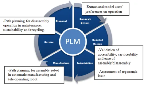
Path planning in assembly and disassembly has significant influence on many processes in product lifecycle from virtual assembly for design verification [1] to parts removal for maintainability studies [2] and robot assembly for automatic production [3], shown as Fig. 1. Assembly is capstone process in manufacturing and one of the most cost effective approaches to high production flexibility [4]. In recent decades, virtual prototyping is already widely applied in industry to lower the cost of production and shorten the production cycle time. The virtual assembly based on 3D CAD model can make the designer intuitively verify the assembly or disassembly operations. However, due to disappearance of some perceptions and shortage of human-computer interaction technology, the virtual assembly presents new challenges to the designers as well [5]. Some of the manual manipulation of 3D object in complex virtual environment is extremely difficult [1].
Defining the assembly process as a precise description of how to move the target part gradually from its initial location to the goal location while never touching the obstacles, sampling based motion planning algorithm search a discrete path with connectivity in part’s configuration space. Among this category of algorithm, Rapidly Exploring Random Trees (RRTs) have been successfully used to solve high level degree of freedom motion planning problems [6]. However, narrow passages which commonly exist in assembly tasks become a bottleneck restricting time reduction of assembly process in PLM. Despite that different heuristics have been created to improve the performance of automatic algorithms, narrow passages are still major issue for sampling based method.
Fig. 1. Path planning for assembly/disassembly applied in product lifecycle
In contrast, humans have the abilities to globally plan motion in complex environment. Based on experience and perception to 3D environment, humans can make fast judgments and response. The skills human lack is accurate computation on geometry. Humans and computer may both encounter trouble in narrow passages. However, when relaxing collision constraints, it’s easier for humans to find a solution.
Moreover, the PLM process impulses on information sharing with all the internal and external actors of companies [7]. However, the automatic algorithms cannot fulfill the gap between users, designers and assembly experts. For example, the designers have to take into account the emotion and perception evaluation of user in maintenance study. At present time, it’s difficult to model humans’ preferences and perceptions in assembly process, even with semantics description. In [8], authors indicated that the closed-loop PLM is more valuable when the interaction is direct between the company and the end user of product. Therefore integration of user into planning process is essential.
In this paper, we present a new interactive frame. Combined with human manipulation, retraction and RRT planners, we allow users guide the computer in difficult scenarios. Human’s participations can accelerate the algorithm as well as make final path in compliance with users’ operating preferences. And in reverse, the interaction process can indirectly extract the experience knowledge from assembly experts and operational preferences of end users.
The paper is organized as follows: in section 2, we provide a brief survey of related work in interactive planning. In section 3, we descript the interactive loop which integrates human manipulation, our random retraction method and BiRRT planner. Simulation results are presented and analyzed in section 4. Section 5 is dedicated to an outlook on future work and the conclusion.
2
Related Work
User’s participations in motion planning process emerge in different prior works. Algorithm in [9] allow users specify some critical via configurations or sub-goals in workspace visually with haptic devices to accelerate the exploration of sampling based algorithm. However, in practical implementation, via configurations in tightly clustered environment is unlikely to be found by human.
A preliminary workspace discretization is done based on decomposition algorithm, and then a corridor between initial configuration and goal configuration is found. Harmonic functions are formulated to provide force feedback, or sampling based method explores this corridor to find a feasible path [10].
Method proposed by [11] is successfully applied to interactive motion planning for steerable needles, but difficult for non-convex assembly object. Although method proposed in [12] simultaneously allows cooperation between user and algorithm, it’s still unable to tackle the situations when user and algorithm both get into trap.
As far as we observed, the existing work can neither apply to highly complex packaging scenarios in mechanical industry nor drive design for assembly processes. The proposed method integrates user to significantly reduce the assembly path planning time in different phases of product lifecycle. Based on the feedback of geometric interference information and ease of operation for inexperienced users, our method strengthens the information flow between user, designer and assembly expert.
3
Interactive Motion Planning Process
3.1 Approach Overview
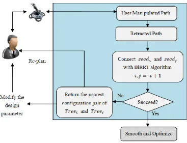
The global view of our interactive assembly motion planning framework is presented in Fig. 2. The more detailed description of process is presented in Fig. 3. The path marked green is user manipulated path. This rough path is then retracted to produce seeds (marked blue) on C-contact space by our Random Retraction Method. BiRRT
algorithm explores between every neighboring two seeds to find a connecting path. The algorithm either finds a solution from q1 to q shown as Fig. 3 (a), or return 8
the nearest configuration pair (marked red) shown as Fig. 3 (b).
Fig. 2. Interactive motion planning process
(a) (b) Fig. 3. Interactive planning in successful case and failed case
3.2 User Manipulation
Based on the fact that user can effectively finish the assembly task in a loose space, we firstly allow user manipulate mechanical parts with some penetration into obstacles. In this manner, user will quickly find a rough path with some configurations in-collision and close to the boundary of C-obstacle space. At the same time, the rough path satisfies user’s operating habits and preference. In this process,
users can choose any kind of interactive devices, no matter using cheap haptic devices or expensive movement tracking system. Moreover, we take a strategy that raise the sampling rate during capture of the human assembly process when user’s operations encounter collisions more frequently and decrease it in opposite situation. This strategy will increase computational efficiency as well as guarantee a perfect description for human’s operations in narrow passages.
Algorithm: Random Retraction Method (RRM) input: Path J(q1,…,qi,…,qn), Obstacles;
for all i do
if collision(qi) = true then
PD = Penetration_Depth(qi,Obstacles);
*[SLT,SLR] = initial();
while PD > threshold(PD) do
Drandom = Random_direction(SLT, SLR);
qnew = Move(qi,Drandom);
PDnew = Penetration_Depth(qnew, Obstacles);
if PDnew < PD then
qi = qnew;
(SLT,SLR,PD) = (SLT*2,SLR*2,PDnew);
else
qnew = Move(qi,~Drandom);
PDnew = Penetration_Depth(qnew,Obstacles);
if PDnew < PD then qi = qnew; (SLT,SLR,PD) = (SLT*2,SLR*2,PDnew); else (SLT,SLR) = (SLT/2,SLR/2); end if end if end while end if end for J = Smooth(J) end
*
SL
TTranslation step length,SL
RRotation step length.3.3 Random Retraction Method
Due to the high computational complexity of global penetration depth, retraction based planners use simple heuristics to explore C-contact space [13]. For example, the algorithm starts from a rough solution and iteratively refines it through shrinking the obstacles and relaxing the collision constraints [1]. Algorithm proposed by [14] allows users generate path by shrinking the object, then improve user-generated path by pushing the in-collision configuration directly to collision-free.
Through defining certain types of distance metric on configuration space, retraction process can be formulated as an optimization problem. In [15], authors use geometric method simulating optimization to get the nearest collision-free configurations in C-contact space. As the boundary of feasible solution region is the C-contact space, and the computation of C-contact space is too complex at present time. Conventional optimization algorithms are either impossible to implement or time-consuming. We provide a randomly retracting method which is based on penetration depth. Compared to pattern search optimization algorithm which uses mesh at each iteration to search a descent direction, our randomly retracting method uses random direction at each step which makes penetration depth value decrease. We also enlarge the step-length when search is successful and reduce it when search is failed. Variable step-length can effectively overcome burdensome computation of penetration depth. Our method will find a solution which is on C-contact space and near to the optimal one.
3.4 Seeds Connection
After retraction, the user manipulated path is transformed into seeds which consist of some collision-free configurations and some configurations on C-contact space. The following process is similar to multi-tree RRT. We use BiRRT algorithm [6] to connect every neighboring two seeds. Since the neighboring two seeds are close to each other, it’s pretty easy for BiRRT planner to find a path between them. In case of that motion planner fails to find a solution within a limited time, we return the nearest configuration-pair in workspace. The interference information is easy to obtain through contact between the configuration-pair and obstacles. The user can make movement adjustments or modify the design size of parts according to the information.
4
Implementation and Results
The following section describes how our interactive system works for the motion planning of a non-convex part passing through a narrow passage. We also demonstrate that the interaction with user equipped by a force feedback joystick can greatly decrease the search space.
All the experiments are performed in the software platform Matlab and on a PC Dual Core, 2.4 GHz and 2 GB ram.
4.1 User Manipulation
In implementation, user manipulates the part in 2D environment with Logitech Force 3D Pro force feedback joystick. The moving object is allowed to have limited penetration into obstacles, which means that the maximum penetration is set by user and any part of the moving object is forbidden to penetrate through the obstacle. And we allow moving object have large penetration into obstacle, but only have collision
with one obstacle at the same moment. User can decide the beginning and end of the motion recording time.
Collision check is realized by detecting the intersected edges between two polygons. Penetration depth is realized by calculating the area of overlap region between two polygons.
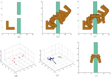
Fig. 4. Successful case for an L shape part passing through a narrow passage Fig. 5. Exploration trace of basic BiRRT
4.2 Results
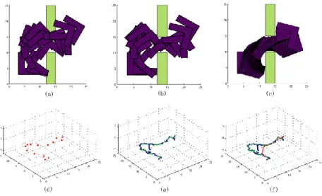
In the situation of Fig. 4, user has to manipulate an L shape part passing through a hole of a wall in 2D environment. The moving part has three degrees of freedom. In this case, the hole is narrow enough that the planning with strict collision detection is time-consuming for both user and basic BiRRT planner. By relaxing the collision, user can quickly manipulate the part pass through the hole, as shown at Fig. 4(a). This rough path manipulated by user is then retracted as shown at Fig. 4(b) and corresponding path in configuration space shown at Fig. 4(d). As the number of configuration recorded for retraction is small, the retraction process doesn’t require much time. From every neighboring two configurations of retracted path, two trees
(marked green and blue) are grown by BiRRT algorithm to connect each other, as shown at Fig. 4(e).
Fig. 6. Comparison between basic BiRRT and our interactive process
Table 1. Comparison between basic BiRRT and our interactive process in case of radius = 5
)
(s
T
allT
C(s
)
T
R(s
)
T
S(s
)
Num
nodeNum
RBasic BiRRT 111.253 109.87 N/A 1.383 354 N/A
M-interactive 13.023 9.1900 1.239 2.594 93 5 Retraction R searched node Smooth S Retraction R Connection
C T T T T T Num Num Num Num
T , , , ,
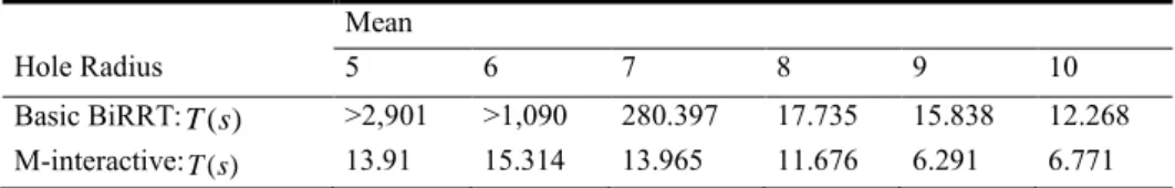
Table 2. Comparison between basic BiRRT and our interactive process in case of different
radius Hole Radius Mean 5 6 7 8 9 10 Basic BiRRT:T(s) >2,901 >1,090 280.397 17.735 15.838 12.268 M-interactive:T(s) 13.91 15.314 13.965 11.676 6.291 6.771
A path successfully passing through the hole is found quickly by our interaction method shown at Fig. 4 (c) (f). In reason that our retraction process provides guidance to exploration of BiRRT, the number of visited configurations and tree search time of BiRRT algorithm are greatly reduced, as shown in Table 1. This result can be observed intuitively through comparison between the exploration trace of basic BiRRT algorithm in Fig. 5 and our interactive process in Fig. 4. From Table 1, we can also find how fast the random retraction process is, which only takes 1.239 seconds for 5 times retraction. We also make the comparison in cases of different radius of hole. For each radius of hole, we run both of the algorithms 5 times respectively, and take the average time. The results are demonstrated in Table 2 and Fig. 6. In challenging situation when the radius of hole is 5, the basic BiRRT will spend more than one hour to find a feasible solution. While in opposite, our method runs about 10 seconds. Moreover, in easy situations, our method also needs less time for planning. Through comparison, our interaction method appears more robust and efficient in planning motion of non-convex part in narrow passage.
In Fig. 7, the hole is designed too small for the part to pass through. However, intuitively detecting the infeasibility is difficult for user in advance of planning. In condition of relaxed collision, user can manipulate the part passing through the hole shown as Fig. 7 (b). After retraction process (shown as Fig. 7 (c) (d)) and connection process (shown as Fig. 7 (e)) of our method, the nearest configurations respectively locating at entrance and exit of the narrow hole can be returned to user, shown as Fig. 7 (f). As a result, the designer can understand the size limitations of accessibility for a product design.
Fig. 7. Failed case for an L shape part passing through a narrow passage
5
Conclusion and Future Work
In this paper, we present an interactive path planning framework for assembly/disassembly process of PLM. Based on randomly retracting method, our method can make user and automatic planner efficiently work together to overcome narrow passages with very tight tolerances. Planning time for assembly task can be greatly reduced. Moreover, our method provides visualized geometric interference information feedback to designer, thereby facilitating designer’s understanding to change and shortening design cycle time. As the generated paths comply with user’s operating habits and preferences, some ergonomic issues can be quickly checked at early phase.
In future work, we will implement our interaction method in industrial cases within virtual environment. It is possible to implement different interactive device for user in virtual world such as 6dof haptic devices or motion tracking system. It is also necessary for us to make a choice on different penetration depth algorithms that can
be applied to our retraction method. Although our system performs perfectly in 2D environment, it still faces some challenging issues in 3D, which includes providing deeper insights on measuring human perception in virtual assembly and facilitating user understand environment from feedback.
References
1. Ferré, E., Laumond, J.P., Arechavaleta, G., and Estevès, C.: Progresses in Assembly Path Planning. In: International Conference on Product Lifecycle Management PLM’05, Lyon, France, pp. 373--382 (2005)
2. Santochi, M., Dini, G., and Failli, F.: Computer Aided Disassembly Planning State of the Art and Perspectives. Journal of CIRP Annals-Manufacturing Technology 51(2): 507--529 (2002)
3. Kohrt, C., Stamp, R., Pipe, A.G., Kiely, J., Schiedermeier, G.: An Online Robot Trajectory Planning and Programming Support System for Industrial. Journal of Robotics and Computer-Integrated Manufacturing 29(1): 71--79 (2013)
4. Hu, S.J., Ko, J., Weyand, L., Elmaraghy, H.A., Lien, T.K., Koren, Y., Bley, H., Chryssolouris, G., Nasr, N., and Shpitalni, G.: Assembly System Design and Operations for Product Variety. Journal of CIRP Annals-Manufacturing Technology 60(2): 715--733 (2011) 5. Lim, T., Ritchie, J.M., Sung, R., Kosmadoudi, Z., Liu, Y., and Thin, A.G.: Haptic Virtual
Reality Assembly–Moving Towards Real Engineering Applications. In: Zadeh, M.H. (ed) Advances in Haptics. InTech, doi: 10.5772/8695 (2010)
6. Kuffner, J.J., and LaValle, S.M.: RRT-connect: An Efficient Approach to Single-Query Path Planning. In: International Conference on Robotics and Automation ICRA’00, vol. 2, pp. 995--1001 (2000)
7. Le Duigou, J., Bernard, A., Perry, N., and Delplace, J.C.: A Constraints Driven Product Lifecycle Management Framework. In: 19th CIRP Design Conference-Competitive Design, pp. 109 (2009)
8. Le Duigou, J., Bernard, A., Perry, N., and Delplace, J.C.: Generic PLM System for SMEs: Application to an Equipment Manufacturer. Jounal of Product Lifecycle Management 6(1): 51--64 (2012)
9. He, X.J., and Chen, Y.H.: Haptic-Aided Robot Path Planning Based on Virtual Tele-Operation. Journal of Robotics and Computer-Integrated Manufacturing 25(4-5): 792-803 (2009)
10. Vazquez, C., and Rosell, J.: Haptic Guidance Based on Harmonic Functions for the Execution of Tele-operated Assembly Tasks. In: IFAC Workshop on Intelligent Assembly and Disassembly IAD’07, pp. 88--93 (2007)
11. Patil, S., and Alterovitz, R.: Interactive Motion Planning for Steerable Needles in 3D Environments with Obstacles. In: IEEE RAS/EMBS International Conference on Biomedical Robotics and Biomechatronics BIOROB’10, pp. 893--899 (2010)
12. Taïx, M., Flavigné, D., and Ferré, E.: Human Interaction with Motion Planning Algorithm. Journal of Intelligent & Robotic Systems 67(3-4): 285--306 (2012)
13. Rosell, J., Vázquez, C., Pérez, A., and Iñiguez, P.: Motion Planning for Haptic Guidance. Journal of intelligent & robotic systems 53(3): 223--245 (2008)
14. Bayazit, O.B., Song, G., and Amato, N.M.: Enhancing Randomized Motion Planners: Exploring with Haptic Hints. In: International Conference on Robotics and Automation ICRA’00, pp. 529--536 (2000)
15. Zhang, L.J., Manocha, D.: An Efficient Retraction-based RRT Planner. In: International Conference on Robotics and Automation ICRA’08, pp. 3743--3750 (2008)