an author's
https://oatao.univ-toulouse.fr/26010
https://doi.org/10.1016/j.compstruct.2020.111902
Broutelle, Marion and Lachaud, Frédéric and Barriere, Ludovic and Daidié, Alain and Chardonneau, Alexandre and
Bouillon, Florent Bearing damage identification in oxide/oxide ceramic matrix composite with a new test design.
(2020) Composite Structures, 236. 1-17. ISSN 0263-8223
Bearing damage identification in oxide/oxide ceramic matrix composite
with a new test design
Marion Broutelle
a,b, Frédéric Lachaud
a,⁎, Ludovic Barrièrre
b, Alain Daidié
a,
Alexandre Chardonneau
a, Florent Bouillon
caInstitut Clément Ader (ICA), Université de Toulouse, ISAE-SUPAERO, INSA, IMT MINES ALBI, UTIII, CNRS, 3 Rue Caroline Aigle, 31400 Toulouse, France bIRT Saint-Exupéry, 118 route de Narbonne – CS44248, 31432 Toulouse Cedex 4, France
cSAFRAN Ceramics, Rue de Touban, Les Cinq Chemins, 33185 Le Haillan, France
Keywords:
Ceramic matrix composite Damage mechanisms Bearing failure
A B S T R A C T
In this paper, the mechanisms of damage of an oxide/oxide ceramic matrix composite bearing are studied with a new experimental setup, the balanced quarter hole device (BQH). This test was designed to allow direct ob-servation of the damage development on a material subjected to bearing failure. In a standard bearing experi-ment, real time monitoring is extremely difficult to set up, and post mortem observations of the bearing plane can be biased by the cutting operation. High speed cameras were used to take pictures of the bearing plane so that the damage development could be studied and a damage chronology established. The validity of the setup was verified by comparing the results obtained with those of a standard bearing test. Two different stacking sequences were studied, and the influence of the material microstructure and composite machining was in-vestigated. It was shown that the first critical damage, matrix cracks, appeared before the load drop, and then led to delamination and kink bands, causing the final failure of the material.
1. Introduction
Due to current economic and environmental requirements, new materials are being introduced in aeronautical structures. Thanks to their low density and their mechanical properties at high temperatures, ceramic matrix composites (CMC) are considered to be good candidates for thermostructural applications. At intermediate temperatures (700–800 °C), oxide/oxide CMC are particularly interesting compared to carbide based CMC. They do not suffer from oxidation issues, and their manufacturing process is less expensive and faster[1].
The mechanical behavior of oxide/oxide CMC relies on the concept of a weak matrix[2]. This concept is allowed by partial sintering during the manufacturing of the composite. The porosity rate and size must be carefully controlled in order to obtain a material with interesting properties[3,4]as the use of a highly porous matrix allows crack flection at the fiber/matrix interface, resulting in fiber/matrix de-bonding and fiber pull out[5,6]. When a crack develops in the porous matrix, it does not break the fiber instantly and the composite lifetime is thus extended. Although the fibers and matrix are fragile, the com-posite shows damage tolerant behavior[1,3].
If oxide/oxide CMC are to be used in hot sections of aircraft engines, it is necessary to study the damage and rupture occurring when the
material is linked with the rest of the structure. In bolted joints, several types of failure can appear[7], depending, for instance, on the geo-metry or the stacking sequence of the specimen[8,9]. There are three main types of failures (net tension, shearing and bearing) to which must be added the mixed modes and bolt failures. This study focuses on the bearing failure, which is a progressive, non-catastrophic degradation during which load transfer remains possible even after the appearance of the first damage[10].
Some studies have focused on the compressive behavior of similar materials. According to Ben Ramdane et al.[11], matrix cracks are initiated by macropores induced by the manufacturing process, and propagate along the fibers, creating delamination in the composite. Delamination is the main damage in the structure and leads to the final failure. Jackson et al.[12]pointed out that, in compression, the be-havior is nearly linear until failure and that the structure fails suddenly just after the first damage (the buckling of the 0° plies).
To the best of our knowledge, there is no reference in the literature for the bearing capacities of oxide/oxide CMC but several authors have studied the damage chronology for similar materials, such as organic matrix composite. Bearing failure is due to an accumulation of several damage events in the structure [10]. This damage consists of fiber micro-buckling leading to kinking, matrix breakage, delamination and
https://doi.org/10.1016/j.compstruct.2020.111902 ⁎Corresponding author.
shear bands through the thickness of the composite[9,13,14]. For Ca-manho et al.[10], the first and most important damage is delamination between the composite plies but other authors consider that kinking is the critical damage that initiates the rest of the failure[15–18]. Another important parameter to be taken into account when dealing with a woven composite is the fiber waviness. The greater the undulations in the fibers, the greater the material’s tendency for delamination[19,11]. A preliminary experimental test campaign performed on the mate-rial showed that the damage leading to bearing failure in oxide/oxide CMC was similar to that in organic matrix composite[20,21]. However, it was difficult to clearly determine the order of appearance of the damage. Therefore, a new test method was designed in order to monitor the damage development in the bearing plane and to obtain a damage chronology for the bearing behavior. Two different stacking sequences were studied and the influence of the fiber waviness was investigated.
2. Material and experimental protocol
2.1. Material
The material studied was a woven composite laminate with an 8 harness satin wave ply, produced by Safran Ceramics. It is composed of alumina fibers (Nextel™ 610) and an alumina matrix. No fiber interface coating was applied. The manufacturing process of the composite began with the infiltration of alumina plies with a slurry containing ceramic particles. Then the fabric was dried at low pressure, and partial sin-tering was performed in order to obtain a material with 25–30% mi-croporosity. Such processing can induce defects in the composite before the tests, such as matrix micro-cracks and macropores[5]. Eight spe-cimens were tested, with two different stacking sequences: [0]10and [0/45/0/45/0]s. Every specimen was examined with an SEM and with
2.2. Sample design
In the preliminary test campaign on standard bearing specimens to characterize the damage development in oxide/oxide CMC[20,21], the tests were stopped at different bearing phases in order to obtain a da-mage chronology. It was shown that some dada-mage appeared on the load drop, as V shaped damage on the bearing plane[20,21]. These ob-servations provided first indications but were not sufficient and it was quite difficult to stop the tests at different points of the load drop stage. Moreover, to observe the damage on the bearing zone with an SEM, it was necessary to cut the specimen. This operation could potentially introduce additional defects, and it was therefore complex to dis-criminate the source of the observed damage.
Consequently, a new experimental procedure needed to be designed to allow direct observation of the bearing plane during the tests (Fig. 1). Schilling et al.[23]performed tests on a full bearing specimen with in situ tomography but this solution was expensive and required a com-plex test setup. Aldebert et al.[24]and Catché et al.[25]studied the damage chronology on the slice of a rectangular composite plate, with an adjusted axis producing a compressive load on the slice. While this setup allowed for the monitoring of the bearing zone, it did not consider the drilling effects (surface roughness, local damage) or the stress in-tensity factor due to the hole, and the contact area between the axis and the plies was not representative of a bolted joint.
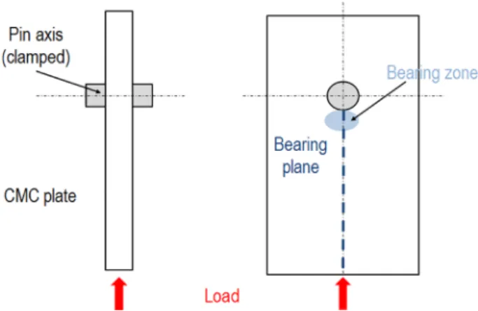
In this paper, the geometry was therefore adapted so as to obtain a contact zone that was more representative of a bearing test (Fig. 2). The setup was designed with two drillings in order to be symmetric. This improved the stability of the specimen, prevented sliding during the test and ensured a quasi-simultaneous failure of the two partial holes. Even when simultaneity was not achieved, the setup still had the interest of allowing access to a history of the bearing damage. This symmetric behavior was monitored thanks to digital image correlation monitoring, by checking that the vertical displacement of the specimen was equivalent on both sides. Moreover, the geometry of the specimen, particularly its free length, ensured that the failure would be a bearing one.
2.3. Tests conditions and instrumentation
The sample was held at its top by an adjustment system that allowed it to be rebalanced at the beginning of the tests. The bearing contact was achieved with two axes made of steel, to which a compression load was applied (Fig. 3.a). Monotonic tests were performed on an Instron 100 kN with controlled displacement. The specimens were loaded at a rate of 0.1 mm/min, at room temperature. The damage development on both slices was monitored in real time with two high speed cameras (Photron FASTCAM SA5 and MINI AX200) taking 100 000 frames per second. This rate of acquisition was chosen before the tests to be sure to record enough data during the load drop phase (about 5 ms). An ana-lysis of the results showed that it could be lowered to 20,000 frames per second without loss of information. The two high speed cameras were synchronized, and the load was recorded in order to be correlated with the pictures taken by the devices. In addition, a digital image correla-tion setup (VIC 3D) was used to measure displacement and strain on the front face of the specimen. The test configuration is presented in Fig. 3.b.
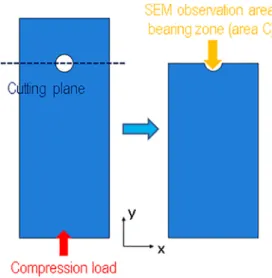
After the tests, an SEM was used to obtain a final cartography of bearing damage inside the holes (area A) and on the slices (area B). Fig. 4is a schematic representation of the areas observed with the high speed cameras and studied with the SEM.
3. Experimental results
3.1. Global mechanical behavior Fig. 1. Modified bearing sample based on ASTM D5961[22]
Fig. 5. Four tests were performed for each lay-up.Fig. 5.a corresponds to the [0]10stacking sequence (BQH11, BQH12, BQH13and BQH14) and Fig. 5.b to the [0/45/0/45/0]sone (BQH21, BQH22, BQH32and BQH33). The mean maximum load was similar for both stacking sequences but the dispersion of the results was greater for the [0/45/0/45/0]s speci-mens. The curves can be decomposed into several stages, presented on one typical curve inFig. 6.
1. Adjustment of the specimen in the test setup (due to clearances) 2. Elastic linear behavior
3. Nonlinear behavior
4. First bearing peak and load drop 5. Load recovery
6. Second bearing peak and load drop 7. Residual load
These stages are quite similar to the ones occurring in a bearing test [20,21], with a linear behavior stage, the appearance of non linearities due to the first damage, a brutal load drop after the peaks, and a
Fig. 5. Experimental curves for the BQH tests. (a) stacking sequence [0]10and (b) stacking sequence [0/45/0/45/0]s.
Fig. 6. Phases of the BQH experimental behavior (BQH22). Fig. 4. Areas observed with the experimental instrumentation of the BQH test.
residual load. The main difference is that there are two peaks, corre-sponding to the bearing failure of each partial hole. Even though the setup was designed to be as symmetrical as possible, the holes did not fail at the same time during the tests, although their failures were quite close. This can also be explained by the fact that the microstructure of the material (the fiber waviness or the distribution of the macro-por-osities) is likely to have been different on each side of the composite. 3.2. Damage chronology
The main damage observed was comparable to that existing in a classical bearing test[10,20,21]: fiber micro-buckling and kink bands, matrix cracking and delamination between adjacent plies (Fig. 7).
Fiber pull-outs were noticeable, proving the efficiency of the weak matrix concept (Fig. 8). Some fibers were also extracted from the slice (Fig. 9). Unlike a standard specimen, the BQH did not have a closed bearing plane (free edge configuration), so there was no material to
retain the fibers in the composite. This fiber extraction constituted additional damage that was not representative of the bearing chron-ology, and it will not be included in the damage chronology.
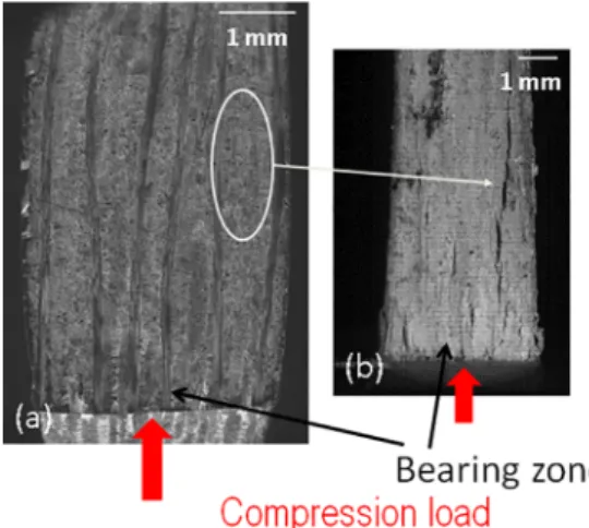
The damage evolution on the slice of the specimens is presented in Figs. 10 and 11. Each image, taken with either the high speed camera or the SEM, shows the damage cartography at a bearing stage. It can be noted that the damage is localized on the external plies of the structure, regardless of the stacking sequence. This can be explained by the fact that the internal plies are contained by the external ones, so the damage evolution is restrained inside the composite.
The damage chronology is quite similar for both stacking sequences. During phase 1 and phase 2, no damage is observed. The first de-gradation is seen in phase 3, which is consistent with the loss of line-arity in the load-displacement curve. The first damage is fiber buckling in the 0° plies (Figs. 10.b and11.b). It can appear on either the internal or external plies, but always close to the contact area between the specimen and the steel axis. This damage is not easily detectable be-cause of the camera resolution, but it seems to exist in several speci-mens.
Fig. 7. SEM images (area B) of damage in the oxide/oxide CMC ([0]10specimen): (a) kink bands due to fiber buckling, (b) matrix cracks and (c) delamination
between plies.
Fig. 8. SEM image (area A) of fiber pull-out in a [0/45/0/45/0]sspecimen. Fig. 9. SEM image (area B) of fiber extraction from the slice of a [0/45/0/45/0] sspecimen.
At the end of phase 3, matrix cracks appear on the slice of the composite, along the longitudinal tows. These cracks do not always emerge at the same location, and sometimes develop millimeters away from the contact zone.
The load drop (phase 4) corresponds to the swelling of the structure induced by the development of new matrix cracks and the propagation of the former one. The damage during this phase is described more precisely in the next section. The weakening of the structure then leads to the appearance of ply buckling, delamination and kink bands, causing the final failure. In several specimens, delaminations are not distributed throughout the thickness but appear first on the external plies of the composite. Then they propagate through the thickness to-wards the internal plies by following the shape of the fiber tows (Fig. 11.c). On the SEM image taken after the tests, it can be seen that the extent of the delamination is greater in the external plies than in the internal ones, and that the final degradation is V shaped (Fig. 11.d).
3.3. Damage kinematics during the load drop phase
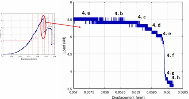
The damage development during stage 4 of the BQH test was pre-cisely studied with the images taken by the high speed cameras. The load displacement curves of two [0/45/0/45/0]sspecimens can be seen onFigs. 12 and 13.Figs. 14 and 15show the mechanical behavior of two specimens exhibiting different degradation patterns.
OnFig. 14, the two first images of the BQH22load drop phase show that some damage (matrix cracks and delamination of an external ply) existed before this stage. During the falling of the load, the delamina-tion extends, new matrix cracks and delaminadelamina-tion appear and the ex-isting ones propagate along the composite (images 4.c to 4.f). It can also be observed that the swelling of the slice occurs during this phase (between images 4.e and 4.f). Finally, at the end of this sequence, the initial delamination leads to the buckling of the external ply of the specimen.
Fig. 10. Damage chronology for the [0]10specimens: (a) before testing (SEM image), (b) first matrix cracks (phase 3, high speed camera image), (c) propagation of
matrix cracks and delamination through the thickness (phase 4, high speed camera image),) and (d) specimen after the bearing failure (phase 7, SEM image).
Fig. 11. Damage chronology for the [0/45/0/45/0]s
specimens: (a) before testing (SEM image), (b) first matrix cracks (phase 3, high speed camera image), (c) propagation of matrix cracks and delamination at the 0°/ 45° interfaces (phase 4, high speed camera image) and (d) specimen after the bearing failure (phase 7, SEM image).
Images 4.a and 4.b ofFig. 15also prove that damage (matrix cracks) occurred before phase 4. Then, in images 4.c to 4.g, corresponding to the sudden load drop, they propagate and new, similar damage is cre-ated. This propagation tends to be greater on the external plies, and a global V-shaped degradation is visible on image 4.i. Similarly to BQH22, the swelling of the composite occurs at the beginning of the fall (be-tween images 4.c and 4.d).
3.4. Comparison of two tests
The damage development can be linked with the macroscopic
behavior. In this section, two specimens presenting the same stacking sequence ([0/45/0/45/0]s) are studied. BQH21 has a higher stiffness before breakage than BQH33but a lower bearing peak load (Fig. 16).
The pictures from the high speed cameras indicate that BQH33 shows cracks almost at the beginning of phase 2, whereas BQH21 ex-hibits its first damage later (Fig. 17). The stiffness degradation being linked with the composite damage, the former specimen maintains its initial stiffness longer than BQH33. The images at the bearing point also show differences between the two specimens (Fig. 18). Both samples exhibit several delaminations but, on the BQH21, their extent is greater. The damage must have propagated faster and more easily on this Fig. 12. Load displacement curve of BQH22during phase 4.
specimen, causing a premature failure.
4. Discussion
4.1. Influence of the material microstructure
The behavior of the two stacking sequences exhibited several si-milarities for damage development. The same damage was noted at the same stages for both lay-ups. The dispersion of the results seems to be linked to the material microstructure rather than to the lay-up.
The presence of a privileged zone for damage appearance and
propagation was found on some specimens. These zones corresponded to locations where the fiber waviness and therefore the matrix fraction were the most marked. OnFig. 19, it is noticeable that the first matrix cracks occur at a place where the fiber waviness induces a surplus of matrix and, onFig. 20, the delamination of the composite propagates over a similar area.
Two phenomena can explain this observation. Firstly, the matrix is less resistant than the fibers in this material, so the matrix surplus in these areas weakens the structure locally and promotes the emergence of the first material degradations. Moreover, the fiber waviness induces a geometric perturbation. The fibers are pre-buckled, so a smaller stress Fig. 14. High speed camera images of damage kinematics (delamination propagation) during the load drop stage (BQH22).
is sufficient to lead to the buckling of the plies. 4.2. Influence of the composite machining
The location of the bearing damage can also be influenced by the machining of a composite, which can cause defects such as fiber ex-traction or matrix breakage, and these can initiate the first damage when the specimen is subjected to a bearing load [26–28]. Fig. 21 shows an example of such a phenomenon. The post mortem SEM pic-ture shows that some 0° tows were broken on the bearing contact area. A comparison with the pre-test SEM image reveals that the location of
such breakage corresponds to the place where the fibers were damaged by the drilling. OnFig. 22, the first matrix crack seems to coincide with fiber degradation due to the cutting operation.
4.3. Comparison with a standard bearing test
The results obtained were compared to those of standard bearing tests in order to assess the relevance of our experimental design. The comparison was made for [0/45/0/45/0]sspecimens, as the available bearing tests were performed with this stacking sequence.Fig. 23shows the bearing specimen geometry and loading conditions. The width of Fig. 15. High speed camera images of damage kinematics (delamination propagation) during the load drop stage (BQH33).
the BQH specimen is smaller than the standard one but both have bearing failure so the qualitative results can be compared.
4.3.1. Load-displacement curves
The load-displacement curves of two representative specimens for Fig. 16. Experimental curves for the BQH21and BQH33.
Fig. 17. High speed camera images of the specimens at the beginning of phase
2: (a) BQH21and (b) BQH33.
Fig. 18. High speed camera images of the specimens at the first bearing peak
(phase 4): (a) BQH21and (b) BQH33.
Fig. 19. Damage appearance related to the microstructure: (a) before testing,
location of the highest matrix fraction (SEM, area B) and (b) during the test, location of the first matrix crack (high speed camera).
Fig. 20. Damage appearance related to the microstructure: (a) before testing,
location of the highest matrix fraction (SEM, area B) and (b), during the test, propagation of a delamination (high speed camera).
Fig. 21. SEM images (area A) of BQH specimens, the machining defects induce
standard bearing and BQH experiments are plotted in Fig. 24. The maximum load is 25% higher on average for the standard test. This can be explained by the fact that the contact zone is smaller with the quarter hole device, the axis only pushing on a partial bearing zone. Moreover, the geometry of the specimens is not the same and this parameter can influence the ultimate load in a bolted joint[8,29,30]. Unlike the standard bearing one, the BQH specimen also presents a free edge; hence the damage is not confined and can develop more easily. For the standard test, the stress at peak can be deduced from the rela-tion σ=(F/d t), where F is the load, t the thickness of the composite plate, and d the hole diameter. However, due to the specimen geometry, this relation is no longer applicable for the BQH device, and the bearing stress cannot be obtained from this test.
4.3.2. Digital image correlation
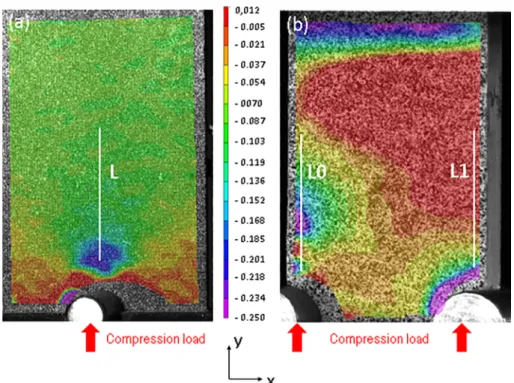
The digital image correlation data were also compared, and the longitudinal strain cartographies at the first bearing point are presented inFig. 25. It can be seen that the cartographies are qualitatively similar: the digital image correlation shows that there is a strain location from the start of the nonlinear phase. This higher strain certainly indicates the appearance of damage in the composite. It is located near the bearing contact zone, over a distance nearly corresponding to the drilling diameter.
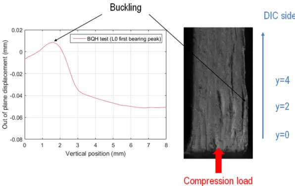
Moreover, the value of the longitudinal strain can be compared for both experiments along a vertical line located on the bearing plane (Fig. 26). For the standard test, the curve is the one obtained at the bearing peak. For the BQH test, the cartographies of both bearing peaks are presented. The line L0 corresponds to the first bearing peak (for the left hole) and the line L1 to the second one (right hole). For both configurations the vertical position y = 0 is taken next to the hole.
At the bearing location (y = 0), all configurations show the same behavior, with a negative strain due to the compressive damage. The value of the strain for the standard bearing is included between those for the BQH test. It can be observed that the strain variation is different for the two bearing peaks of the BQH, but this can be explained by the different behaviors of the two holes. For L0, the study of the out of plane displacement indicates that the specimen is subjected to a local buckling on the external ply at the first bearing point (Fig. 27). This may explain the fact that the longitudinal strain oscillates along the bearing plane and that its value is higher for y = 2 than for y = 4. In contrast, on the bearing plane L1, there is no buckling but only a swelling of the material on the bearing zone (Fig. 28). These observa-tions are confirmed by the camera images, with buckling appearing on Fig. 22. Images of BQH specimens; the machining defects induce cracks (a)
Image before testing (SEM, area B) and (b) image during the experiment (high speed camera).
Fig. 23. Bearing specimen geometry and loading conditions (DIC image).
Fig. 24. Experimental load displacement curves for standard bearing and BQH
the side of the DIC for L0 but only on the opposite side for L1. When observing DIC results, some distinctions can be noted, in particular between the two holes of a BQH specimen. The two sides can break differently as the applied load cannot be entirely symmetric in the setup, and the DIC device only allows observation of one side of the specimen.
However, the DIC analysis shows that the BQH specimens behave in a similar way to the standard ones: the strains are similarly distributed at the bearing peaks, with equivalent values of strain for both config-urations.
4.3.3. Damage observations
For both configurations, bearing damage was studied. Post mortem observations were achieved using an SEM, with images taken inside the hole (Fig. 29, area C) and on the bearing plane (after cutting the spe-cimen for the standard bearing tests,Fig. 30, area D).
Moreover, some X-ray tomographies were performed for the stan-dard experiments. Regarding the BQH experiment, damage was also monitored with high speed camera images on the bearing plane. Several resemblances were noticed:
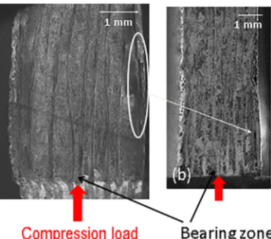
- The location of the main damage: on both configurations, the ex-ternal plies were more damaged that the inex-ternal ones (Fig. 31). Moreover, on some specimens, the external plies (0° plies) were broken due to a compression failure (Fig. 32).
- On the SEM images, it can be seen that the edges of some 0° rows are missing, due to the buckling of the plies near the bearing contact (Fig. 33)
- There are fiber kink bands near the contact zone, on the bearing plane of the composite (Fig. 34).
- The same V-shaped damage can be observed through the thickness of the composite, on the bearing plane (Fig. 35).
4.3.4. Stress distribution in the contact zone
Finite element analyses were performed on Abaqus in order to compare the stress distribution on the contact zone for BQH and bearing specimens for [0/45/0/45/0]slay-up. The computation uses the Full Newton Raphson solver (ABAQUS General Standard) with nonlinear geometric activation.
The CMC specimen was meshed at ply level, with twenty quadratic C3D8 elements (Abaqus reference) per ply (brick elements with eight Gauss point and three DoF per nodes) and represents the half of the test specimen (Fig. 36). For this computation, the CMC behavior was Fig. 25. Longitudinal strain cartography (%) at the first bearing point: (a) standard bearing test, (b) BQH test.
considered to be linear elastic. The pin axes were modeled by rigid quadrangular shell elements R3D4 (Abaqus reference). The contact between the two parts was modelled with a normal component (“hard” contact) and a tangential one (penalty contact with a friction coefficient of 0.3). Pin axes are considered the master and sample the slave.
The boundary conditions are representative of the two configura-tions. For each sample, pin axis was clamped and an imposed dis-placement equal to −0.1 mm was applied to the opposite face (Fig. 36).
The same model was used for the bearing and BQH samples, only the symmetric conditions on the x direction change.
A convergence study was performed in order to validate the FE model. The mesh density according to the thickness direction varies between one and thirty two elements. The results show for BHQ sample model and for out of plane stresses distribution (Fig. 37), that con-vergence is obtained for twenty elements in the ply thickness. We used the same mesh for bearing sample model.
Fig. 27. Out of plane displacement at the first bearing peak (BQH22, L0).
To compare the mechanical behavior of both configurations, a de-lamination criterion[31]was calculated along a path created on the z axis:
= + +
f ( /zz Rzz)2 ( /xz Rxz)2 ( yz/ Ryz)2
The material delaminates when f exceeds the value 1. The values of σzzR, σxzR and σyzR were obtained through a previous experimental campaign aimed at obtaining the mechanical parameters of the oxide/ oxide CMC by testing it with tension, compression, or shearing tests. The results of the delamination criterion for a displacement corre-sponding to the bearing displacement are presented inFig. 38.
The results are consistent with the experimental observations; in particular, delamination occurs at the same locations as predicted by the criterion. For both tests, the CMC tends to delaminate at the 0°/45° interfaces, and the delamination is greater on the external plies due to the free boundary conditions.
It can be noted that the BQH criterion is quantitatively higher than the standard bearing one. This confirms that the free edge in the BQH test could enhance delamination depending on the layup. In some other configurations to be determined, delamination could become pre-ponderant and such a BQH test could not be compared to standard bearing test. In contrast, some layups could exhibit no difference in terms of delamination criterion, as can be seen inFig. 39for the [0]10 stacking sequence. For this layup, the BQH setup does not enhance delamination, it even tends to reduce it on the external plies. However, even if there is no delamination, some intra ply debonding can be seen in the composite. Performing finite element simulations gave an insight into the order of magnitude of delamination differences due to the BQH test configuration.
4.3.5. Validity of the BQH test
These different comparisons tend to validate the interest of the BQH device when it comes to the study of damage developing in the bearing plane of a composite. The similarities regarding the macroscopic be-havior, the strain and numerical stress distributions or the type of da-mage prove that the same mechanical behavior appears in both ex-perimental configurations.
It is also necessary to be aware of the limits of such an experiment. In the BQH device, the contact zone is not exactly the same as the bearing one, leading to a difference in the maximum load. This differ-ence is also induced by the free edge in the BQH device, which cannot contain the damage as a standard bearing specimen would. This leads to fiber extraction from the slice of the specimen, damage that must not be taken into account for the bearing chronology. Depending on the stacking sequence, the BQH setup can also enhance the delamination between the plies, especially if there are 0°/45° interfaces. Moreover, in comparison with a standard bearing test, an additional flexion around the z axis is induced by the setup configuration. However, this flexion does not seem to induce any marked effect in the analysis of bearing damage.
5. Conclusion
The bearing failure mechanism of an oxide/oxide CMC was in-vestigated through an experimental campaign. An original test set up was designed in order to obtain an accurate damage chronology of the material, with direct visual observation of the bearing plane. This new experimental design also brought additional information for modelling the bearing mechanical behavior by making the cracks easier to follow. Fig. 29. First SEM observation area (inside the hole).
Fig. 30. Second SEM observation area (on the bearing plane/bearing zone).
Fig. 31. SEM images of the specimen after the tests, showing the external plies
more damaged than the internal ones: (a) on a standard bearing test (area C) and (b) on a BQH test (area A).
The bearing failure is due to an accumulation of multiple de-gradations including kink bands, matrix cracks and delamination. The first significant damage seems to be matrix cracking. The micro-structure of the material plays an important role in the damage initia-tion as the cracks tend to appear on the zones with the highest matrix fraction, which are weaker than the rest of the structure.
The setup developed in this study relies on a new specimen geo-metry with a bearing load applied to two partial holes. The BQH test presents some differences with a conventional bearing test as the con-tact zone is not exactly the same and an additional flexion appears during the tests. Moreover, the edge effects induce supplementary da-mage: fiber extraction from the slice of the composite. However, these Fig. 32. SEM images of the breakage of the external plies: (a) on a standard bearing test (area D) and (b) on a BQH test (area B).
Fig. 33. SEM images of tow breakage: (a) on a standard bearing test (area D) and (b) on a BQH test (area A).
differences were taken into account in the analysis. It is also important to note that the information deduced from the BQH tests remains qualitative. This setup was designed to obtain a damage scenario but cannot be used to determine the bearing stress of a material.
Some improvements could be added to the instrumentation of the test in order to obtain more information. The acquisition rate of the high speed camera was chosen before the tests, but it could be lowered in order to obtain a better resolution for the pictures. This would allow the propagation of cracks to be followed more precisely. It would also be interesting to use some digital image correlation on the slices of the specimen (in addition to the one on the front) to map the strain in this area too.
It could be relevant to investigate the consequences of a misalign-ment of the specimens in the BQH device. To decrease the calculation time, the first finite element model that was proposed in this paper was purely symmetric but modelling the whole device could allow the misalignment phenomenon to be studied.
Fig. 35. Damage after failure on the slice of the specimen: (a) tomography of
the bearing plane on a standard bearing test and (b) high speed camera image on a BQH test.
U=V=Z=0
Reference Point Clamped
Contact Zone Pin Axis
U = 0 : Symmetric plan for classical bearing sample
U = 0 : Symmetric plan for BQH sample
V = - 0,1 mm Imposed displacement
Z = 0 : Symmetric plan for the laminate
Fig. 36. Numerical model of the configurations.
0 20 40 60 80 100 120 140 160 180 200 0 5 10 15 20 25 30 35
Ma
xi
mu
m
O
ut
of
plan
e s
tr
ess
es
(MP
a)
Number of finite element in each ply
SZZ
SXZ
SYZ
BQH: SYZ BQH: SXZ BQH: SZZDeclaration of Competing Interest
The authors declare that they have no known competing financial interests or personal relationships that could have appeared to influ-ence the work reported in this paper.
Acknowledgement
The authors would like to thank Safran Ceramics for its scientific contribution to the subject and for suppling the test material.
Appendix A. Supplementary data
Supplementary data to this article can be found online athttps:// doi.org/10.1016/j.compstruct.2020.111902.
References
[1] Keller KA, Jefferson G, Kerans RJ. Oxide-Oxide composites. Handbook of Ceramic Composite. 2005. p. 377–421.
[2] Koch D, Tushtev K, Grathwohl G. Ceramic fiber composites: Experimental analysis and modeling of mechanical properties. Compos Sci Technol 2008;68:1165–72. [3] Zok FW, Levi CG. Mechanical properties of porous-matrix ceramic composites. Adv
Eng Mater 2001;3:15–23.
[4] Mattoni MA, Yang JY, Levi CG, Zok FW. Effects of matrix porosity on the me-chanical properties of a porous-matrix, all-oxide ceramic composite. J Am Ceram Soc 2001;84(11):2594–602.
[5] Ben Ramdane C. Etude et modélisation du comportement mécanique de CMC oxyde/oxyde (PhD thesis). Université de Bordeaux; 2014.
[6] Simon RA. Progress in processing and performance of porous-matrix oxide/oxide composites. Int J Appl Ceram Soc 2005;2(2):141–9.
[7] Heimbs S, Schmeer S, Blaurock J, Steeger S. Static and dynamic failure behavior of bolted joints in carbon fibre composites. Compos A 2013;47:91–101.
[8] Collings TA. The strength of bolted joints in multi-directional CFRP laminates. Composites 1977;8(1):43–55.
[9] Kelly G, Hallstrom S. Bearing strength of carbon fibre/epoxy laminates: effects of bolt-hole clearance. Compos B 2004;35:331–43.
Fig. 38. Delamination criterion of both configurations for [0/45/0/45/0]sstacking sequence.
laminated composite materials. Compos Sci Technol 2006;66:3004–20. [11] Ben Ramdane C, Julian-Jankowiak A, Valle R, Renollet Y, Martin E, Diss P.
Microstructure and mechanical behaviour of a NextelTM610/alumina weak matrix
composite subjected to tensile and compressive loadings. J Eur Ceram Soc 2017;37(8):2919–32.
[12] Jackson PR, Ruggles-Wrenn MB, Baek SS, Keller KA. Compressive creep behavior of an oxide-oxide ceramic composite with monazite fiber coating at elevated tem-perature. Mater Sci Eng A 2007;454–455:590–601.
[13] Wu PS, Sun CT. Modeling bearing failure initiation in pin-contact of composite laminates. Mech Mater 1998;29:325–35.
[14] Wang HS, Hung CL, Chang FK. Bearing failure of bolted composite joints. Part I: experimental characterization. J Compos Mater 1996;30(12):1284–313. [15] Sola C, Castanie B, Michel L, Lachaud F, Delabie A, Mermoz E. On the role of
kinking in the bearing failure of composite laminates. Compos Struct 2016;141:184–93.
[16] Seike S, Takao Y, Wang WX, Matsubara T. Bearing damage evolution of a pinned joint in CFRP laminates under repeated tensile loading. Int J Fatigue
2010;32:72–81.
[17] Xiao W, Ishikawa T. Bearing strength and failure behavior of bolted composite joints (Part I: experimental investigation). Compos Sci Technol 2005;65:1022–31. [18] Hirano N, Takao Y, Wang WX. Effects of temperature on the bearing strength of CF/
epoxy pinned joints. Compos Sci Technol 2007;41(3):335–51.
[19] Lachaud F, Piquet R, Aldebert G, Huet J, Michel L. Analyse du comportement mécanique des assemblages boulonnés composites à renforts tissés. Revues des Composites et des Matériaux Avancés 2014;24(4):449–64.
[20] Broutelle M, Lachaud F, Dupleix-Couderc C, Daidie A. Comportement en matage de composites à matrice céramique oxyde/oxyde. JNC20, Champs-sur-Marnes, 18-30
June 2017.
[21] Broutelle M, Lachaud F, Daidie A, Barriere L, Dupleix-Couderc C, Bouillon F. Mechanical behavior of oxide/oxide ceramic matrix composite bolted joints. ECCM 2018, Athens, 25-28 June 2018.
[22] ASTM, Standard Test Method for Bearing Response of Polymer Matrix Composite Laminates, 2010.
[23] Schilling P, Karedla BR, Tatiparthi AK, Verges MA, Herrington. X-ray computed microtomography of internal damage in fiber reinforced matrix composites. Compos Sci Technol 2005;65:2071–8.
[24] Aldebert G, Lachaud F, Huet J, Piquet R. Etude de la cinétique d’endommagement en matage des composites à renforts tissés. JNC17, Poitiers, 15-17 June 2011. [25] Catche S. Analyse des défauts de paroi de trou et de leur criticité sur la tenue
mécanique des structures mécaniques percées (PhD thesis). Université de Toulouse; 2013.
[26] Catche S, Piquet R, Lachaud F, Castanie B, Benaben A. Analysis of hole wall defects of drilled CFRP laminates. J Compos Mater 2014;49(10):1223–40.
[27] Persson E, Eriksson I, Zackrisson L. Effects of hole machining defects on strength and fatigue life of composite laminates. Compos A 1997;28:141–51.
[28] Rahme P, Landon Y, Lachaud F, Piquet R. Lagarrigue. Delamination-free Drilling of Thick Composite Materials. Compos A 2015;72:148–59.
[29] Okutan B. The effects of geometric parameters on the failure strength for pin-loaded multi-directional fiber-glass reinforced epoxy laminate. Compos B 2002;33:567–78. [30] Caprino G, Squillace A, Giorleo G, Nele L, Rossi L. Pin and bolt bearing strength of
fiberglass/aluminium laminates. Compos A 2005;36:1307–15.
[31] Hashin Z. Failure criteria for unidirectional fiber composites. J Appl Mech 1980;47:329–34.
![Fig. 5. Experimental curves for the BQH tests. (a) stacking sequence [0] 10 and (b) stacking sequence [0/45/0/45/0] s.](https://thumb-eu.123doks.com/thumbv2/123doknet/2940657.79102/4.892.469.825.326.617/fig-experimental-curves-tests-stacking-sequence-stacking-sequence.webp)
![Fig. 7. SEM images (area B) of damage in the oxide/oxide CMC ([0] 10 specimen): (a) kink bands due to fiber buckling, (b) matrix cracks and (c) delamination](https://thumb-eu.123doks.com/thumbv2/123doknet/2940657.79102/5.892.194.702.80.426/images-damage-oxide-specimen-buckling-matrix-cracks-delamination.webp)
![Fig. 10. Damage chronology for the [0] 10 specimens: (a) before testing (SEM image), (b) first matrix cracks (phase 3, high speed camera image), (c) propagation of](https://thumb-eu.123doks.com/thumbv2/123doknet/2940657.79102/6.892.198.701.82.385/damage-chronology-specimens-testing-matrix-cracks-camera-propagation.webp)