Contents lists available atScienceDirect
European Journal of Mechanics / B Fluids
journal homepage:www.elsevier.com/locate/ejmfluAerodynamics analysis of wheel configurations in Paralympic
hand-cycling: A computational study
Paul Mannion
a,b,d,∗, Yasin Toparlar
b, Magdalena Hajdukiewicz
a,d, Eoghan Clifford
a,d,
Thomas Andrianne
e, Bert Blocken
b,caDepartment of Civil Engineering, College of Engineering and Informatics, National University of Ireland Galway, University Road, Galway, Ireland bDepartment of the Built Environment, Eindhoven University of Technology, P.O. box 513, 5600 MB Eindhoven, The Netherlands
cDepartment of Civil Engineering, KU Leuven, Kasteelpark Arenberg 40 – bus 2447, 3001 Leuven, Belgium dInformatics Research Unit for Sustainable Engineering (IRUSE), Galway, Ireland
eDepartment of Aerospace and Mechanical engineering, University of Liège, Allée de la Découverte, 9 Quartier Polytech 1, B52/3, B-4000 Liège, Belgium
h i g h l i g h t s
• CFD simulations of hand-cycle setups with wheel rotation.
• Aerodynamic impact of hand-cycling rear wheel spacing is investigated.
• Commercially available wheel combinations are investigated to identify optimal selection.
• Validation of simulations with wind tunnel experiments and comparison with the literature.
a r t i c l e i n f o
Article history:
Received 7 October 2018
Received in revised form 22 December 2018 Accepted 22 January 2019
Available online 6 February 2019
Keywords: Wheel Aerodynamics Hand-cycling Paralympics Crosswinds
Computational fluid dynamics
a b s t r a c t
Para-cycling aerodynamics holds additional complexities compared to its able-bodied counterpart. Hand-cycling provides such an example, where three wheels opposed to the two wheels of a traditional bicycle are required. Wheel aerodynamics are therefore even more prevalent in the field of Paralympic cycling. However, there has been little attention devoted to wheel aerodynamics in Paralympic hand-cycling. This study investigates hand-cycling wheel aerodynamics. The optimal wheel selection was investigated from a combination of wheels that represented competitive deep-section spoked wheels and disk wheels. In addition to the various wheel combinations, the spacing between the two rear wheels was varied. A 55 cm rear wheel spacing provided drag reductions of up to 4.7% compared to 70 cm when using rear disk wheels at 0◦yaw. Crosswinds were also investigated, and it was shown that a front disk wheel
coupled with rear deep-section wheels at 55 cm spacing provided the best aerodynamic drag performance with increasing yaw angle. With this wheel setup, the CDA increased by only 7.7%, between min and max
values found at 0◦and 15◦yaw respectively.
© 2019 Elsevier Masson SAS. All rights reserved.
1. Introduction
Hand-cycling is a Union Cycliste Internationale (UCI) registered cycling sport, with appearances in regional and world para-cycling events and the Paralympics. Athletes compete within 5 classes; H1–H5. The classes of H1–H4 feature a recumbent athlete position on the hand-cycle, with lower levels of athlete impairment from H4 to H1 [1]. The H5 class features a kneeling position com-monly referred to as an upright position, where the athlete can use his/her arms and torso to provide power, whereas the H1– H4 classes are limited to just arm-provided power. Competitive
∗
Corresponding author at: Department of the Built Environment, Eindhoven University of Technology, P.O. box 513, 5600 MB Eindhoven, The Netherlands.
E-mail address:[email protected](P. Mannion).
hand-cycles have three wheels; one front and two rear. The two rear wheels on a competitive hand-cycle are free-rolling, without steering mechanisms. The front wheel is typically centred at the front of the hand-cycle and manages the power application to the ground, braking, gearing and steering. In contrast to traditional cycling, the steering axis is close in orientation to the horizontal ground plane, resulting in the front wheel tilting side to side when steering. Rules set by the UCI restrict the spacing for the rear wheels [1]. Maximum and minimum rear wheel spacings are 70 cm and 55 cm respectively, measured from the point of contact of the wheels with the ground. A range of wheel types are allowed to be used for both road race and time-trial events for both the front and rear wheels; including disk and spoked wheels. Also, cambered wheels are allowed and are predominantly featured in the H5 class. Furthermore, a range of wheel diameters as classified by the Eu-ropean Tyre and Rim Technical Organisation (ETRTO) are allowed,
https://doi.org/10.1016/j.euromechflu.2019.01.011
cycling, inferring the possibility for aerodynamics optimisation. Increasing numbers of publications in the field of elite able-bodied cycling aerodynamics in recent years illustrates the impor-tance of this research field [2–4]. Indeed, approximately 90% of the energy expenditure for cyclists at velocities in excess of 54 km/h is to overcome aerodynamic forces acting on them [4,5]. Hand-cyclists can have average velocities in the range of 35–40 km/h on flat terrain with negligible wind conditions, but, can achieve velocities in excess of 54 km/h in descent phases of race events. Elite able-bodied cycling research has focused on drafting phe-nomena [2,6–9], drag interference effects with cars and motorcy-cles [10,11], athlete posture optimisation [12–18], and leg rotation effects [19,20]. Tandem cycling aerodynamics has been addressed by Mannion et al. [21–23] who used both wind tunnel experiments and computational fluid dynamics (CFD) simulations.
There is little published research in the field of elite hand-cycling aerodynamics. The London 2012 Paralympics initiated the first known hand-cycling aerodynamics research, to the best knowledge of the present authors. Mazzola et al. [24] investigated athlete ergonomic and aerodynamic variables, and concluded that efforts to improve ergonomics such as raising the inclination of the backseat, negatively affected the aerodynamic performance. Belloli et al. [25] conducted an experimental study of hand-cycling aerodynamics, using wind tunnel experiments and track tests. Drag area (CDA) values of 0.21 m2and 0.20 m2were measured in
the wind tunnel experiments for a recumbent hand-cyclist (H1– H4 category) in a propulsive (actively applying power) and aero-dynamic (static arms) stage respectively. A wider CDA range was
found for an upright hand-cyclist (H5 category), with CDA values of
0.22 m2and 0.13 m2measured for the propulsive and aerodynamic
stages respectively. Indeed, the lowest CDA recorded in the wind
tunnel campaign was 0.13 m2for a H5 class hand-cyclist in an
aero-dynamic non-propulsive position [25]. More recently, Mannion et al. [26] conducted an experimental and numerical investigation of hand-cycling aerodynamics. Scaled wind tunnel experiments were used to provide measurement data for the validation of a series of numerical simulations. Yaw angles between 0◦
–20◦
in 5◦
increments were investigated for a static hand-cyclist geometry, with simplified wheel geometries that represented three spoked wheels for a road race setup, and three disk wheels for a time-trial (TT) setup. Maximum and minimum CDA ranges for the road setup
with spoked wheels were 0.1850 m2 and 0.1621 m2at 15◦
and 0◦
yaw respectively. The TT setup with three disk wheels yielded lower CDA values, with maximum and minimum values of 0.1322
m2 and 0.1205 m2 at 5◦and 20◦ respectively. The roll moment trends were found to match the lateral force trends with increasing yaw angle, where the roll axis was defined on the ground plane between the front wheel and the right rear wheel.
The aerodynamics of bicycle wheels have been a widely re-searched topic in relation to cycling aerodynamics, and the present study on wheel aerodynamics for hand-cycling applications builds from data available in the literature by Godo et al. [27]. Godo et al. [27] investigated the performance of several commercial bicycle wheels using CFD. Two velocities of 8.9 m/s (20 mph) and 13.4 m/s (30 mph) were considered over a range of yaw angles (0◦ , 2◦ , 5◦ , 8◦ , 10◦ , 12◦ , 14◦ , 16◦ , 18◦ and 20◦
), and the results were correlated against available wind tunnel data. Six different wheels were tested, including the Zipp 404, Zipp 808, Zipp 1080, Zipp Sub9, HED TriSpoke and the Rolf Sestriere. The data reported by Godo et al. [27] concerning numerical and experimental drag coefficients for the Zipp 404 spoked wheel and the Zipp Sub9 disk wheel were utilised in the present research to validate numerical simulations. The numerical results by Godo et al. [27] for these two wheel types showed good agreement to their experimental data,
force trends matching their experimental counterparts.
A gap in the literature was identified regarding knowledge of the optimal wheel selection for hand-cycling; considering com-mercially available wheels instead of simplified wheel geometries. Furthermore, wheel rotation has not been accounted for in nu-merical studies of hand-cycling aerodynamics. The present study investigated the impact of wheel selection on the aerodynamics of a Paralympic hand-cycling setup using two commercially available wheels used in competitive cycling. Wheel rotation was accounted for along with the impact of crosswinds and the positioning of the rear wheels within the spacing allowable by the UCI. This study used CFD as the primary investigative tool, validated using wind tunnel experiments and experimental data available in the literature. A set of simulations of isolated wheel geometries were conducted for the purpose of validating the numerical method used for modelling wheel aerodynamics. The findings of this study informed a second set of simulations that modelled hand-cycling aerodynamics. Section2introduces the geometrical models and the CFD parameters used. The validation studies are described in Section 3, while the results, discussion and conclusions are presented in Sections4–6respectively.
2. Simulation setups 2.1. Geometrical models
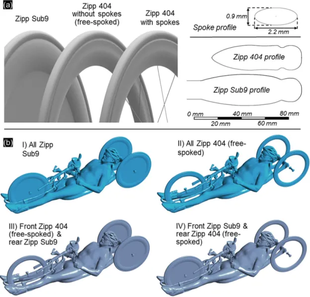
The hand-cyclist’s geometry for this study was obtained via 3D scanning using the Artec Eva structured light 3D scanner [28]. Informed consent was acquired prior to scanning from the ath-lete involved. The Zipp Sub9 disk wheel and the Zipp 404 deep-section spoked wheel were selected for this study (Fig. 1a). The rim and hub profiles for both wheels were obtained from [27,29] and modelled using CAD software. The spokes for the Zipp 404 were elliptical Sapim CX-ray spokes, 2.2 mm long and 0.9 mm thick [30]. Two wheel diameters were used, 0.695 m and 0.611 m respectively, maintaining the same rim and tyre profiles. Note that the diameter values mentioned are the total diameters of the wheels, for ease of comparative purposes. The 0.695 m diameter wheels were used to validate the numerical method to simulate rotating disk and spoked wheels, by allowing direct comparisons to the wind tunnel experiments and numerical simulations reported by Godo et al. [27]. The 0.611 m diameter wheels were considered representative of typical sizes used in competitive hand-cycling and were utilised in the CFD simulations. Smooth slick tyres were assumed for all wheels, with no grooves present.
The small geometrical details of the spokes for the Zipp 404 present challenges when generating computational grids, and the resulting high cell count yielded a high computational expense for the simulations in terms of solver time and working memory. Thus, two versions of the Zipp 404 were investigated. The first was fully spoked, and the second had the geometry of the spokes removed, leaving the tyre, rim and hub to represent the wheel geometry (Fig. 1a). The latter wheel geometry was termed as a ‘free-spoked’ wheel. The focus of this free-spoked wheel geometry without the spokes was to determine if it was necessary to model the spokes in numerical simulations, with the aim of reducing the computational cost of the simulations and enabling a wider comparative study that included several wheel combinations, rear wheel spacings, and yaw angles.
The Zipp Sub9 and free-spoked Zipp 404 wheels were coupled with the hand-cyclist’s geometry to generate a number of geom-etry variations. Four geomgeom-etry variations were created based on wheel selection as outlined inFig. 1b, all with 55 cm rear wheel spacing. These included (I) three Zipp Sub9 wheels, (II) three free-spoked Zipp 404 wheels, (III) a front free-free-spoked Zipp 404 wheel
and rear Zipp Sub9 wheels, and (IV) a front Zipp Sub9 wheel coupled with free-spoked Zipp 404 rear wheels. The impact of rear wheel spacing was investigated on hand-cycles with three Zipp Sub9 wheels (combination I), and front Zipp Sub9 with rear Zipp 404 wheels (combination IV). Four spacings were used for both geometries between the maximum and minimum spacings allowed by the UCI; 55 cm, 60 cm, 65 cm and 70 cm. All hand-cycle and wheel geometries were raised 2 cm from the ground surface, to prevent skewed mesh cells from forming at the wheel–ground in-tersection point; this method is evident in the literature [10,11,22]. The front forks and rear axle were simplified to accommodate the computer aided design (CAD) and grid processes when exchanging the wheel geometries, and their spacing when modelling the rear wheels.
2.2. Boundary conditions and solver settings
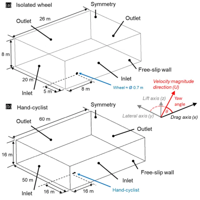
Two computational domains were used throughout this work. The first domain was for an isolated wheel, depicted inFig. 2a. Best practice guidelines [31–34] were followed to ensure that the wheel geometry was placed at a sufficient distance from the inlet (minimum of 5 times the wheel diameter) and outlet boundaries (minimum of 10 times the wheel diameter) respectively, and that the blockage ratio remained below 3%. Two inlet and two outlet boundary conditions were used to simulate yaw angles, by having the same velocity magnitudes and directions at the inlets. A sym-metry condition was used for the top surface of the domain, and a free-slip wall was used for the ground surface. In the case of 0◦
yaw, the inlet and outlet boundary conditions parallel to the direction of fluid flow were changed to symmetry conditions. A rotational velocity was applied to the wheel geometries corresponding to a 13.4 m/s travelling velocity using the rotating wall boundary condition. A velocity magnitude of 13.4 m/s was maintained for all yaw angles when simulating the isolated wheels, as per the tests by Godo et al. [27]. Yaw angles of 0◦
, 2◦ , 5◦ , 8◦ , 10◦ , 12◦ , 14◦ , 16◦ , 18◦ and 20◦
were investigated for both the free-spoked Zipp 404 wheel and the Zipp Sub9 disk wheel. The yaw angle was defined as the incidence angle of the air against the travelling direction of the wheel as per Godo et al. [27], illustrated inFig. 2.
The second computational domain for the geometry of the hand-cyclist resembled in shape the first computational domain used for the isolated wheel (Fig. 2b). Again, best practice guide-lines [31–34] were followed for the domain dimensions. Boundary conditions as per the isolated wheel computational domain pre-viously discussed were also applied. An effective velocity magni-tude of 15 m/s with 0.2% turbulence intensity and 1 m hydraulic diameter was maintained for all yaw angles. A 0 Pa ambient zero static gauge pressure outlet was used for all outlet boundaries. Yaw angles of 0◦, 5◦, 10◦, 15◦and 20◦were simulated. Rotating wall boundary conditions were again used to simulate the wheel rotation in the hand-cycling simulations.
ANSYS Fluent [35] was used to solve the Reynolds-averaged Navier–Stokes (RANS) equations, using a 2-equation turbulence model to achieve closure; namely the Shear Stress Transport (SST)
k-
ω
turbulence model [36]. The pseudo-transient solver was used with the Coupled pressure–velocity coupling algorithm and the second-order order discretisation schemes for turbulent kinetic energy and specific dissipation rate. Second-order pressure inter-polation was used and gradients were computed using the Least Squares Cell Based method. The pseudo time-step size was 0.01 s, and all force values were averaged over 4000 steps after an initial-isation period for statistically steady-state results as per Mannion et al. [26].2.3. Computational grids 2.3.1. Wheel computational grids
Separate systematic grid sensitivity studies were conducted for the disk Zipp Sub9 and free-spoked Zipp 404 wheels. Four tetrahedral-prismatic grids were created for the disk wheel, with the cell size at the surface systematically refined for each succes-sive grid. The max y* for each grid was held below 1 for each of the four grids, with 26 prism layers that maintained a height of 1
×
10−5m for the wall-adjacent cell and with a growth ratio of1.2. A growth ratio of 1.1 was used for the volume grid outside of the prism layers. Each of the four grids were tested using a static no-slip wall boundary condition, and a rotating wall boundary condition, to determine the sensitivity of the grid resolution to the static and rotating wheels.
The four grids for the disk wheel were named D1, D2, D3 and D4 with cell counts of 3,945,512, 9,336,891, 23,299,082 and 46,164,126, respectively. The subscript ‘S’ and ‘R’ was added to the grid names inFig. 3to define between static wheels and rotating wheels, respectively. Both the static wheel and rotating wheel sim-ulations were found to exhibit a similar degree of grid convergence. The Grid Convergence Index (GCI) suggested by Roache [37,38] was calculated for both static and rotating simulations using grids D2, D3 and D4. GCIs of 1.04% and 0.26% were calculated for grids D4S
and D4R, respectively using the drag force as the target parameter,
indicating acceptable levels of grid convergence. A GCI of 1.33% was calculated for grid D3R.
Grid sensitivity studies were conducted on the static (no ro-tational modelled) free-spoked Zipp 404 wheel. Four systemati-cally refined tetrahedral-prismatic grids were created for the free-spoked wheel. These grids are denoted as S1, S2, S3 and S4 in
Fig. 3, and had cell counts of 3,646,649, 8,800,024, 22,484,414, and 45,252,126, respectively. 26 prism layers with a first cell height of 1
×
10−5 m and a growth ratio of 1.2 were also used on thiswheel geometry, to limit any variation to y* across each of the four grids. A growth ratio of 1.1 was used for the volume grid outside of the prism layers. The grid sensitivity appeared to approach its asymptote after grid S2. A GCI of 1.46% and 1.82% was calculated for grid S4 and S3, indicating an adequate level of grid convergence. Two grids were created for the spoked Zipp 404 wheel that investigated the sensitivity to the number of cells along the length of the spokes. Mapped quad cells were used to discretise the surface geometry of the spokes. Each spoke contained 32 cells around its circumference to capture the curvature of the elliptical shape. Individual refinement ratios were applied to both ends of the spokes to ensure good transition to the rim and hub. The grid resolution of grid S3 was applied for the wheel rim and hub, and the same volume grid parameters including the 26 prism layers were applied. The two grids contained 220 cells and 320 cells respectively along the length of the spoke, and were named S3220
and S3320appropriately. It was noted that a cell count far below
the 220 cells across the length of the spokes (such as a count of 120) resulted in stretched cells that compromised the quality of the grid. The sensitivity study of the spokes revealed a low sensitivity between S3220and S3320, with a difference of 0.31% between the
CDA calculated for both simulations.
Based on the grid sensitivity studies, the grid parameters for grids D3 and S3 were deemed to have sufficient accuracy and were chosen for further study. These results were used for comparison against experimental and numerical data of isolated wheels in the literature, and were applied on the wheels used in the hand-cycle simulations. Grid S3220was used for further comparison in
Fig. 1. (a) Three wheel geometries under study: Zipp Sub9 disk, free-spoked Zipp 404 and Zipp 404 with spokes included. (b) Depiction of hand-cycle geometry with four
variants of wheel combination variations.
2.3.2. Hand-cycle computational grids
Three grids were created to test the grid sensitivity for the hand-cycle geometry; a coarse (H1), medium (H2) and fine grid (H3), each systematically refined. Simplified spoked wheels were used in this study instead of the Zipp 404 or Zipp Sub9, that were not based on any commercial design and that contained twelve spokes with diameters of 12 mm. The grid cell counts were 10,404,121, 27,236,409, and 77,363,247 cells for grids H1–H3, respectively. A GCI of 0.29% was calculated for grid H3, and 1.29% for grid H2. Thus, the parameters for grid H2 were chosen as providing acceptable accuracy for further simulations, and were combined with the grid parameters for the disk and spoked wheels previously analysed. The cell counts for the four wheel combinations (I, II, III, IV) described inFig. 1b with 55 cm rear wheel spacing were 51,706,184, 47,778,172, 49,002,622, and 50,445,308, respectively. In addition, a fifth grid was created based on combination IV with a front Zipp Sub9 disk wheel, but with rear Zipp 404 spoked wheels with the geometry of the spokes included. This fifth grid contained 90,998,827 cells.
The grid resolutions are depicted inFig. 4, with the volume grid for a hand-cycle setup with a front Zipp Sub9 wheel and rear free-spoked Zipp 404 wheels, combination IV, in the vertical centre-plane inFig. 4a.Fig. 4b and c illustrate the prism layers used to
resolve the boundary layer on the wheels (Fig. 4b) and the hand-cycle frame (Fig. 4c). It is noted that the same boundary layer grid parameters were applied to all wall surfaces for each of the cycle grids. The surface grid resolution on the athlete legs, hand-cycle frame, and Zipp Sub9 disk wheel is illustrated in Fig. 4d.
Fig. 4e depicts the surface grid resolution on the athlete’s head and helmet along with the Zipp 404 wheel.Fig. 4f and 4g illustrate the grid density for the spoked wheels, with the quad surface grid for the spokes depicted inFig. 4g.
3. Validation studies
Two independent validation studies were performed. The first was to validate the method used for modelling the rotating free-spoked Zipp 404 wheels and Zipp Sub9 disk wheels via qualita-tive comparison to the wind tunnel experiments and numerical simulations reported by Godo et al. [27]; discussed in Section3.1. The second validation study, reported by Mannion et al. [26], consisted of wind tunnel experiments conducted for a static H1–H4 category cyclist to validate numerical simulations of hand-cycling aerodynamics in yaw conditions, and discussed briefly in Section3.2.
Fig. 2. Computational domain for (a) the isolated wheels, and (b) the hand-cyclist.
Fig. 3. Grid convergence for isolated wheels; namely a static Zipp Sub9 disk wheel,
a rotating Zipp Sub9 disk wheel, a static Zipp 404 wheel with the spokes removed, and static Zipp 404 wheels with 220 and 320 cells along the length of each spoke. ‘S’ and ‘D’ stand for spoked and disk wheels, respectively. Subscripts ‘S’ and ‘R’ stand for static and rotating, respectively.
The drag area (CDA) was used to describe the drag force data and
is described as follows:
CDA
=
FD
0
.
5ρ
U2 (1)where FDis the drag force [N], A is the reference area [m2], U is the
velocity magnitude [m/s], and
ρ
is the air density [kg/m3].3.1. Isolated rotating wheels 3.1.1. Disk wheels
Fig. 5a compares drag areas calculated for the Zipp Sub9 disk wheel across a range of yaw angles: 0◦
, 2◦ , 5◦ , 8◦ , 10◦ , 12◦ , 14◦ , 16◦ , 18◦ and 20◦
. Data from wind tunnel experiments conducted by Zipp and reported by Godo et al. [27] were used in the comparison. In addition, the CFD simulations conducted by Godo et al. [27] at 13.4 m/s (30 mph) were also compared. The drag trend across the yaw range investigated was found to closely match that reported by Godo et al. [27], where increases and decreases in drag were found in reaction to the yaw angle. The drag experienced by the wheel was observed to reduce between yaw angles 0◦
–8◦
. The drag then increased between yaw angles 8◦–10◦, decreased between yaw angles 10◦
–16◦
, and increased again between yaw angles 16◦
– 20◦
Fig. 4. (a) Volume grid density in vertical centre-plane. (b) Prism layers resolving boundary layer on the Zipp Sub9 disk wheel. (c) Boundary layer grid around the frame
crank. (d) Surface grid density on the athletes’ legs, frame and disk wheel. (e) Surface grid density on the athlete’s head and helmet and on the Zipp 404 wheel. (f) Surface grid density on the wheel hub. (g) Grid density on the spokes (220 cells along spoke length).
5◦
, 8◦
, 10◦
and 12◦
with a maximum difference of 0.0006 m2. A
similar trend was reported from the wind tunnel experiments by Zipp. However, the absolute drag values from the wind tunnel experiments at 0◦
–8◦
were considerably higher than the numer-ical results of Godo et al. [27] and the numerical models of the present research; up to 0.0095 m2 at 0◦
yaw. In addition, it was reported that the Zipp Sub9 disk wheel experienced a positive thrust force at a yaw angle of 12.5◦
, which was not predicted by the numerical simulations by Godo et al. [27] or the present research.
It is noted that there is a lack of knowledge regarding the wind tunnel experiments conducted by Zipp in the publication by Godo et al. [27], including the shape and size of the wheel supports, how rotation was transferred to the wheel, details of ground boundary or wind tunnel test bed, the approach flow boundary layer, block-age, tyre roughness, turbulence intensity, and sensor uncertainties. However, the overall qualitative agreement between drag trends predicted by Zipp, the numerical studies of Godo et al. [27] and the present study is considered to be acceptable for the Zipp Sub9 disk
wheel. The level of variability between independent investigations of aerodynamic drag is indicated by the numerous drag values reported by Godo et al. [27] for 0◦
yaw, from 0.0061 m2to 0.0156 m2, from various studies with drag data available for the same or
similar wheels. A CDA of 0.0061 m2was predicted from the present
research.
3.1.2. Free-spoked wheels
Fig. 5b compares drag coefficients calculated for the Zipp 404 wheel across yaw angles from 0◦
–20◦
, between the present re-search and the numerical results of Godo et al. [27] at 13.4 m/s, and the wind tunnel results from Zipp, as reported by Godo et al. [27]. The Zipp 404 wheels used in this study neglected the geometry of the spokes, and contained only the wheel rim, tyres and hubs. The same drag trends throughout the yaw range investigated were found for the numerical results reported by Godo et al. [27], the experimental results from Zipp, and the present research. An offset was observed between the drag predictions by the experimental results from Zipp and the numerical results from Godo et al. [27]. In addition, there was a further offset between the numerical results from Godo et al. [27] and the present study, with an averaged deviation of 33.6%. This can be attributed to the absence of the spokes in the wheel geometry. In addition, any support structures from the wind tunnel experiments by Zipp and the ground contact patch are not replicated in the present study, making meaningful direct quantitative comparisons difficult. A range of drag values were reported by Godo et al. [27] for 0◦
yaw, as obtained from other studies. The max and minimum CDA measurements at 0◦
yaw were 0.0190 m2 and 0.0064 m2respectively, and the value
predicted by the present study falls within this range, at 0.0066 m2, even without the spokes modelled. The level of agreement
between the present results and the numerical reported by Godo et al. [27] and the wind tunnel data from Zipp are considered fair for the reproduction of the drag trends under yaw conditions, taking into consideration the removal of the spokes from the wheel geometry and that the ground contact patch is not accounted for in the present study. However, as previously mentioned for the Zipp Sub9 disk wheel, there is a lack of knowledge regarding the apparatus and exact settings employed for the wind tunnel exper-iments conducted by Zipp [27]. Godo et al. [27] also demonstrated a dependency on Reynolds number for both the Zipp 404 spoked wheel and the Zipp Sub9 disk wheel, with the drag trend at 8.9 m/s (20 mph) similar to that at 13.4 m/s (30 mph) but offset in absolute values by a maximum of 9.6%.
The differences between the results of Godo et al. [27] and the present study could be attributed to several factors. Regarding the Zipp 404 wheel, this included the removal of the spokes from the Zipp 404 wheel geometry. The blockage ratio (defined as the frontal area divided by the fluid domain cross-sectional area) for the present study was lower than that from Godo et al. [27], where blockage ratio ranged from 1.4% at 0◦
to up to 9.7% at 20◦
for the Zip Sub9 disk wheel. This blockage would have resulted in artificial accelerations around the wheel that would impact the drag results. By comparison, the maximum blockage ratio the present study was 0.013%. In addition, the contact patch between the wheel and the ground was modelled differently in the present study and by Godo et al. [27]. The contact patch between a tyre and the ground was measured by Godo et al. [27] and implemented in the numerical simulation. However, in the absence of this data, the wheels in the present study were raised 2 cm from the ground surface which pre-vented skewed cells from forming at the tangent point of contact which would have negatively impacted the discretisation error of the numerical solution.
Fig. 5. Comparison of CDA values of the present study to the wind tunnel data from
Zipp and the numerical results from Godo et al. [27] for (a) the Zipp Sub9, and (b) the (free-spoked) Zipp 404.
3.1.3. Spoked wheels
To determine the impact of the spokes on the wheel aerody-namics, additional static simulations were performed at 0◦yaw of the Zipp 404 wheel with the spokes included. Grid S3220was used
as described in Section2.3. The total drag of the static wheel was found to increase by 11.7% when the geometry of the spokes was included in the simulation. Furthermore, the drag breakdown of the tyre-rim, hub and spokes was 69.6%, 17.3% and 13.1% respec-tively. This compares to the values reported by Godo et al. [29] for the same wheel simulated; 70.7%, 13.1% and 16.2% respectively. The spokes were found to have a comparable drag to the wheel hub, and the majority of the drag was generated by the rim at 70.7%, indicating that removing the geometry of the spokes could be a viable option for simulating wheel aerodynamics. The present study was static and the wheel rotation was accounted for by Godo et al. [27] and thus the differences between the comparison of static and rotating wheels are noted. The advancing spoke in the rotating wheel would experience a different oncoming flow to its diametrically opposite spoke. However, if the spokes are not considered, the comparisons of the rotating free-spoked Zipp 404 wheel to the wind tunnel data by Zipp and the numerical data by Godo et al. [27] show that the same drag trends were captured in crosswind conditions.
To conclude the investigation into the necessity of modelling wheel spokes, a static simulation was performed of a hand-cyclist with two fully-spoked Zipp 404 wheels attached to the rear axle (55 cm rear wheel spacing) along with a disk Zipp Sub9 wheel on the front, to test the feasibility of simulating hand-cycling aero-dynamics with the geometry of the spokes included. The resulting
the rear axle, whose grid size was 49,002,622 cells by comparison. A 0.5% increase in total CDA was found by including the geometry
of the spokes. Thus, it was determined that the geometry of the spokes for the Zipp 404 wheel could be removed to ensure the computational cost of further simulations remained viable without significantly impacting the drag of the hand-cyclist. It is noted that from this point, all Zipp 404 wheels without the geometry of the spokes are referred to as ‘free-spoked wheels’ and all Zipp Sub9 wheels are referred to as ‘disk wheels’ for efficient reporting and dissemination purposes.
3.2. Hand-cycle validation studies
The lateral force area (CSA) was used to describe the lateral force
data from the wind tunnel experiments and numerical studies on hand-cycling aerodynamics, and is defined as follows:
CSA
=
FS
0
.
5ρ
U2 (2)where FSis the drag force [N].
3.2.1. Experimental and numerical setup
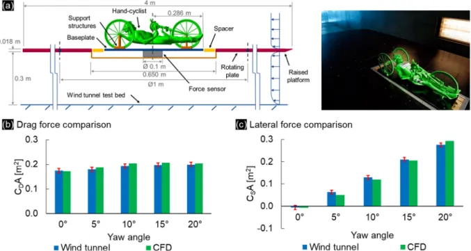
High speed quarter-scale wind tunnel experiments at 60 m/s were conducted in the aeronautical test section of the tunnel in the University of Liège, Belgium, as depicted inFig. 6a. These experi-ments were reported by Mannion et al. [26], and are reiterated here for completeness. Reynolds number similarity to a full-scale hand-cyclist at 15 m/s was acquired using a velocity of 60 m/s for the quarter-scale model. The scaled hand-cyclist geometry was solid and manufactured from ABS (acrylonitrile butadiene styrene); its surface was considered smooth. The model was static in nature, with no movement of the arms or wheels. A manufacturing dimen-sion constraint of 3 mm limited the minimum thicknesses to this size, such as the diameter of the spokes. However, this aided in ensuring model stiffness in view of the high speed experiments. The force sensor used was a commercially available ATI Delta model [39], and was aligned with the centre of gravity of the model. A conservative
±
1.24 N error range was reported for the sensor. The wind tunnel setup is illustrated inFig. 6a. A raised sharp-edged platform was used to remove the model from the boundary layer at the bed of the wind tunnel. A rotating plate was built into the platform to allow for yaw angles to be investigated. Blockage corrections by Barlow et al. [40] were applied, where the maximum blockage ratio was 2.3% at 20◦yaw. A Pitot tube was used for velocity measurements, and temperature variations were also measured to correct air density variations. The air density was also corrected to a standard atmospheric pressure of 101 325 Pa as per the CFD simulations via local meteorological data. The procedure for the wind tunnel experiments was as follows. After setting up the experiment as perFig. 6a, the force sensor was tared under no-wind conditions. The desired velocity was then achieved in the tunnel, and a settling period of 30 s was allowed for the sensor before commencing force measurements. Drag and lateral force data were measured at a rate of 10 Hz for 180 s. Each experiment was repeated for yaw angles of 0◦
, 5◦
, 10◦
, 15◦
, and 20◦
. The numerical simulations for the validation study were pre-sented by Mannion et al. [26], and the computational domain and boundary conditions are discussed in full detail there. The geometrical model is briefly reiterated here for completeness. The upper surface of the platform and the support structures in the geometrical model of the hand-cyclist were included in the CFD simulations. The geometry of the hand-cyclist was rotated using interface conditions to achieve matching yaw angles to the wind tunnel experiments. The geometry was static with no movement in the arms or wheels as per the wind tunnel experiments. The computational parameters matched those discussed in Section2.2.
predictions followed the same overall trends as their experimental counterparts. The numerical simulations correctly matched the direction of a low lateral force (Fig. 7, y direction) at 0◦
yaw, and the increasing lateral force in the opposite direction thereafter (Fig. 6c). In addition, a low deviation was found in the absolute force values between the numerical and experimental results. The average numerical drag deviation from the experimental results was 3.6% respectively. The average lateral force deviation was 9.1%. It is noted that the geometries used in the CFD simulations for this validation study matched those used in the wind tunnel experiments, including the wheel supports, baseplate, and plat-form depicted inFig. 6a. All aerodynamic force predictions from CFD and wind tunnel experiments were considered to be in good agreement.
4. Results
The results chapter is divided into two sub sections. The first, Section4.1, investigates the aerodynamics associated with the rear wheel spacing. The second, Section4.2, investigates the four wheel setups illustrated inFig. 1b under crosswind conditions and with the minimum and maximum rear wheel spacings allowed by the UCI [1].
The pressure coefficient (CP) was used in the analysis of the
numerical studies of hand-cycling aerodynamics:
CP
=
∆P0
.
5ρ
U2 (3)where∆P is the pressure difference between the location of
inter-est and the ambient static pressure [Pa].
4.1. Rear wheel spacing
The spacing between the two parallel rear wheels on a competi-tive hand-cyclist can be adjusted between a minimum of 55 cm and a maximum of 70 cm (Fig. 7), which represent the inner and outer limits set by the UCI [1]. The spacing is measured from the point of contact of the wheel with the ground. This investigation was aimed to determine the optimum spacing for disk and free-spoked wheels on the rear axle of a hand-cycle to optimise aerodynamic drag. Four wheel spacings were simulated; 55 cm, 60 cm, 65 cm and 70 cm, each centred from the front wheel. All wheels were simulated as rotating, and the yaw angle was 0◦
for this study. All wheels were vertical with no camber.
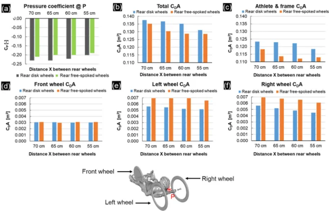
The pressure coefficient was extracted from the simulations at P for all four spacings. Point P was located at the centre between both rear wheels; illustrated inFig. 7. Wheel combinations I and IV were used, with disk (I) and free-spoked wheels (IV) on the rear wheel and a disk wheel on the front axle for both combinations.Fig. 8a compares the pressure coefficient at P for each of the setups. The under-pressure between the two wheels at P was found to decrease with smaller rear wheel spacings. This was found for both free-spoked and disk wheels on the rear axle. For the case of disk wheels, the smaller wheel spacings had a larger impact on the under-pressure than the free-spoked wheels, with a 13.1% reduction in under-pressure between 70 cm and 55 cm, by comparison to 10.1% for the free-spoked wheels.Fig. 8b shows that the total drag was reduced for smaller rear wheel spacings. This finding was observed for both disk and free-spoked wheels. A net drag reduction of 4.7% was found for the disk wheels between 70 cm and 55 cm rear wheel spacings, while the drag was reduced by 4.9% using free-spoked wheels between the same spacings.
The channelling of air between the two disk rear wheels may be reduced by the smaller wheel spacings due to the frontal area of the
Fig. 6. (a) Experimental setup. (b,c) Comparison of experimental and numerical (b) drag, and (c) lateral force area predictions.
Fig. 7. Breakdown of hand-cycle components, illustrating the distance ‘X’ between the rear wheels, and the location of point P for pressure coefficient point measurements.
rear wheels being partially hidden behind the torso of hand-cyclist, and experiencing the wake flow from the hand-cyclist opposed to the free-stream flow. This theory was supported by a breakdown of the drag to just the athlete and frame surfaces, as perFig. 8c. A reduction in drag of similar proportions to the total CDA was found
for the athlete and frame surfaces with reduced spacing between rear disk wheels, which suggests a reduction in the channelling effect. An absolute reduction of 0.0064 m2was found for the total
CDA between 70 cm and 55 cm with rear disk wheels, and an
absolute CDA reduction of 0.0048 m2 was found for the athlete
and frame surfaces combined for the same setup. The free-spoked wheel setups followed a similar trend for the drag experienced by athlete and frame surfaces (Fig. 8c). However, the minimum drag occurred at 60 cm rear wheel spacing opposed to the minimum spacing of 55 cm. This may be due to interaction between the free-spoked wheels and the wake of the hand-cyclist.
A drag breakdown of the wheels inFig. 8d–f provides further in-sight to the aerodynamic impacts of the rear wheel spacing.Fig. 8d presents the drag experienced by the front disk wheel for all setups, where a low variability was found. This was attributed to the front wheel being centred far upstream from the rear wheels. Decreasing drag was found for both the left (Fig. 8e) and right wheel (Fig. 8f) regardless of wheel type with smaller rear wheel spacings. This was attributed to the frontal area of the wheels exiting the free-stream flow and entering the wake flow of the hand-cyclist. The maximum drag reductions between 70 cm and 55 cm rear wheel spacings were 7.8% and 20.5% for the left and right disk wheels respectively, and 5.4% and 12.0% for the free-spoked wheels. Note that the athlete was not symmetric but leaning slightly to his right. The hand-cycle frame was also not symmetric with brake handles, gear handles, mirror and sprocket cowel (safety cover) located at a
CDA [m2] Cp[–] @ P ∆CDA ∆CP
Combination I55: Front
disk, rear disk
Static 0.1292 −0.2045
+1.4% −1.0% Rotating 0.1311 −0.2024
Combination IV55: Front
disk, rear free-spoked
Static 0.1278 −0.1944
+0.6% −1.1% Rotating 0.1286 −0.1923
single side. These non-symmetric geometric features are responsi-ble for the right wheel experiencing greater drag reductions than the left.
It is noted that contrary to expectation, using disk wheels on the rear axle offered a less aerodynamic setup for the hand-cyclist opposed to free-spoked wheels for all wheel spacing’s tested (Fig. 8b). The disk wheels themselves experienced a lower drag than their free-spoked counterparts, but the negative impact of the disk wheels on the athlete and frame upstream was larger than the benefits to the wheels themselves.
Further investigations were conducted to evaluate the impact of the wheel rotation on the channelling effect between the rear wheels, and the subsequent drag experienced by the hand-cyclist. The smallest rear wheel spacing of 55 cm was chosen for the evaluation of combinations I and IV, where both static and rotating wheels were simulated. The results are presented inTable 1. The static disk wheels with combination I were found to have a small impact on the total CDA by comparison to rotating wheels, with
a drag difference of 1.4%. The rotating wheels resulted in a drag increase for the hand-cyclist, similar to the drag finding for isolated static and rotating disk wheels (Fig. 3). A smaller difference was found for the combination IV setup with rear free-spoked wheels, where a CDA difference of 0.6% was recorded. The rotating
simula-tion again experienced a higher drag than the static wheel setup. It was noted that the larger under-pressure value was recorded for the rotating wheel setups, but the overall impact of the rotating wheels compared to static wheels at 0◦
yaw was small. Differences of
−
1.0% and−
1.1% were found for the pressure coefficient at point P, for combination I with the rear disk wheels, and combination IV with rear free-spoked wheels, respectively. Modelling the wheels as static or rotating did not seem to have a significant impact on the drag of the hand-cyclist, and it may be possible that modelling wheels as static may be sufficient for some cycling studies depend-ing on the objective. This can be seen elsewhere in the literature for cycling aerodynamics applications (Blocken et al., [2]). In addition, the rotation of the wheels did not appear to have a significant impact on the channelling effect between the two rear wheels. However, the geometry of the Zipp 404 wheels in this study did not contain any spokes, and it may be possible that the addition of spokes in a simulation that accounts for wheel rotation (e.g. sliding grid method) may affect the under-pressure between the two rear wheels, and consequently the drag of the hand-cyclist.4.2. Crosswinds investigation
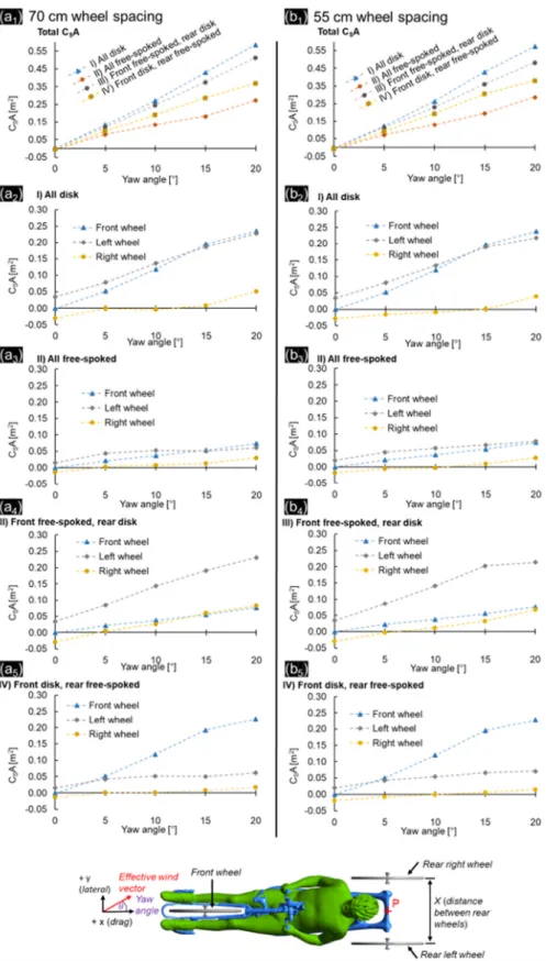
Four wheel setups as described inFig. 1b (combinations I–IV) were investigated under yaw angles of 0◦
, 5◦
, 10◦
, 15◦
and 20◦
. Two rear wheel spacings were analysed for each of the four setups; 70 cm and 55 cm, the maximum and minimum allowable by the UCI [1]. This resulted in a total of 40 simulations for this study, with a typical grid size of 50 million cells. For efficient dissemination purposes, the rear wheel spacing dimension is added in subscript to the combination number. For example, combination IV55is the
front disk–rear free-spoked wheel setup with 55 cm rear wheel spacing.
CDA values are presented inFig. 9a1-b1for the 70 cm and 55 cm
wheel spacings respectively. Small variations (
≤
5%) were found in55 cm wheel spacing’s experienced a lower drag than their equiva-lent setups with 70 cm wheel spacing’s. The total CDA values were
found to disperse with increasing yaw angle. A distinctive trend was found for both rear wheel spacing’s, with hand-cycle setups that featured a front free-spoked wheel performing worse than the setups that featured a front disk wheel at yaw angles between 10◦
– 20◦
.
Maximum drag was observed at 15◦
yaw for all wheel varia-tion setups, and minimum drag at 0◦
. At a rear wheel spacing of 70 cm and 0◦
yaw, the hand-cycling setup with three free-spoked wheels (combination II70) provided the lowest CDA of 0.1305 m2,
followed by the front disk–rear free-spoked setup at 0.1352 m2
(combination IV70), the front free-spoked–rear disk setup at 0.1364
m2(combination III70), and lastly the all disk wheel setup at 0.1375
m2(combination I
70). The 55 cm rear wheel setups resulted in a
lower total drag for each of the wheel combinations than the 70 cm spacings at 0◦
yaw. The same trend in the two best performing wheel setups, combinations II and IV, was also found at a 55 cm rear wheel spacing and 0◦
yaw. Combination II55yielded a CDA of
0.1284 m2, and combination IV
55yielded a CDA of 0.1286 m2, 0.2%
larger. Combination I55provided the second largest drag for the
55 cm wheel setup at 0◦
yaw, at 0.1311 m2and 2.1% greater than
combination II55, and combination III55yielded a CDA of 0.1326 m2
which was 3.3% greater that combination II55. However, the best
performing wheel setups at 0◦
did not hold throughout the yaw angles investigated. The combination IV wheel setups provided the second lowest CDA at 0◦yaw for both rear wheel spacings, but
provided the lowest CDA between 5◦–20◦for the 55 cm rear wheel
spacings, and between 10◦
–20◦
for the 70 cm rear wheel spacing. The combination III55setup provided the highest CDA values from
0◦
–15◦
, and the combination III70setup from 5◦–20◦yaw.
The drag experienced by each of the wheels across the four setups in crosswind conditions is mapped out inFig. 9a2−5for the
70 cm rear wheel spacing, and inFig. 9b2−5 for the 55 cm rear
wheel spacing. Similar drag trends across both rear wheel spacings were observed for each of the hand-cycling wheel combinations. Thrust forces (negative drag) were found opposed to drag forces on disk wheels for several yaw angles. At 10◦, 15◦and 20◦yaw, thrust forces were experienced by the front disk wheel in both the all-disk wheel setup, and the front disk–rear free-spoked wheel setups. Thrust forces were observed on the front disk wheels for both the 70 cm and 55 cm rear wheel spacings. For combination I70, the
thrust force experienced by the front wheel at 20◦
yaw (
−
0.0023 m2) was similar in magnitude to the drag force experienced byeither the left or right rear disk wheels (0.0022 m2and 0.0030 m2 respectively, normalised as CDA). The left disk wheel in the
combi-nation I70and combination III70, also experienced a thrust force at
10◦
. However, these thrust forces were near-zero with CDA values
of
−
0.0006 m2and−
0.0001 m2respectively. However, the dragtrend throughout the range of crosswinds for the left disk wheel for combinations I70, III70, I55, and III55bore some resemblance to
the trend reported from the Zipp wind tunnel experiments [27] for an isolated Zipp Sub9 disk wheel. It is noted that the left wheel is the most removed from the wake and interference effects from the frame and athlete geometry of the three wheels on the hand-cycle; the right wheel is submerged in the wake of the hand-cycle as the yaw angle increases. The peak drag force was observed at 0◦
yaw for the left wheel disk wheel in the aforementioned wheel setups (combinations I70, III70, I55, and III55), and the minimum drag was
observed at 10◦
yaw which equated to a small thrust force, after which the drag rose to a value at 20◦
yaw which was less than half of the drag experienced at 0◦yaw. The thrust force recorded in the wind tunnel experiments by Zipp was reported to be at 12.5◦
Fig. 8. Comparisons at different wheel spacing’s for (a) pressure coefficient at point P, (b) total CDA, (c) athlete and frame CDA, (d) front wheel CDA, (e) left wheel CDA, and
(f) right wheel CDA.
a thrust force at any yaw angle for any of the wheel combinations or rear wheel spacing’s, due to being submerged in the wake of the hand-cyclist as the yaw angle increased.
The front free-spoked wheels in combinations II and III, and for both rear wheel spacing’s, experienced drag trends (Fig. 9a–b) similar to that of an isolated free-spoked wheel (Fig. 5b). Maximum drag was recorded at 20◦
and minimum drag at 10◦
. The left free-spoked wheel in each of the aforementioned setups also experi-enced a similar trend, albeit with higher drag forces throughout due to the increased exposure to the free-stream air than the front wheel, which is located between the legs of the athlete. The right free-spoked wheel for all respective setups experienced drag trends similar to that of its disk wheel counterpart, with the drag reducing for increased yaw angles, due to being placed further within the wake of the hand-cyclist.
The lateral forces experienced by the hand-cyclist setups fol-lowed intuitive trends throughout the yaw range, based on the area exposed to the free-stream air. The rear wheel spacing had a low impact on the total CSA. Combination II55−70provided the lowest
CSA values at yaw angles between 5◦ to 20◦ (Fig. 10a–b). This
setup was followed by the combinations IV55−70, and combinations
III55−70and I55−70followed in third and fourth places respectively.
At 0◦
yaw, the wheel choice for the hand-cyclist had a negligible influence on the lateral force, but as the yaw angle increased, the free-spoked wheels experienced lower lateral forces than their disk wheel counterparts, which had a high impact on the total lateral force. The right wheel for all wheel combinations and rear wheel spacing’s was influenced the least by increasing yaw angle in terms of lateral force. This was due to the wake flow of the hand-cyclist enveloping the right wheel with increasing yaw angle. At yaw angles of 0◦, the left and right wheels (both disk and free-spoked) were found to experience near-equal lateral forces in opposite directions due to the low-pressure region generated on one side of the wheel, from the air being channelled between the two wheels. This occurrence was also observed at 5◦
for some
wheel setups, albeit with the left wheel experiencing a higher lateral force than the right wheel due to its increased exposure to the free-stream air.
5. Discussion
Two independent validation studies coupled with several grid sensitivity studies were conducted to ensure reliable CFD simula-tions were used for this research. Several grid sensitivity studies ensured suitable spatial discretisation. Wind tunnel experiments were used to validate the CFD methodology for a static hand-cyclist in crosswind conditions. To confirm that rotating wheels were modelled accurately, isolated rotating Zipp Sub9 disk and free-spoked Zipp 404 wheels were simulated and the results compared to wind tunnel and numerical data available in the literature [27]. These studies confirmed the reproduction of drag trends in cross-wind conditions for both wheels. Furthermore, it was confirmed that the representative drag trend of the free-spoked Zipp 404 wheel could be attained with the geometry of the spokes removed, thus reducing the computational cost of further numerical investi-gations.
Four rear wheel spacings (for competitive H1–H4 class hand-cyclists) were investigated in this study at 0◦
yaw. Two wheel setups were used, combinations I and IV (Fig. 1b) to investigate the impact of the rear wheel spacing’s when disk wheels or free-spoked wheels were used on the rear axle of the hand-cycle. The four rear wheel spacing’s consisted of consecutive spacing’s in 5 cm increments were tested between a maximum and minimum of 70 cm and 55 cm allowed by the UCI regulations. For smaller rear wheel spacings, the drag on both the rear wheels, the athlete and frame geometries was reduced. This was observed for both disk and free-spoked wheels. Maximum aerodynamic drag reductions of 4.7% were found for disk wheels at a 55 cm rear wheel spacing (opposed to a 70 cm rear wheel spacing), and 4.9% for the spoked wheels (at the same spacings). It was noted that the free-spoked wheels contained only the tyres, rim and hub, and that the
Fig. 9. Drag area breakdown for each of the four hand-cycling wheel setups under crosswind conditions, for (a) 70 cm rear wheel spacing and (b) 55 cm rear wheel spacing.
rotating spokes might have impacted the under-pressure region between the two rear wheels. Furthermore, a 0.1% difference in total drag was found between the 55 cm and 60 cm rear wheel spacings with combination IV (rear free-spoked wheels). 60 cm rear wheel spacing would be preferable to the 55 cm spacing in this case due to the additional stability provided by the larger spacing. The drag benefit for the 55 cm rear wheel spacing was found to hold through 0◦
to 20◦
yaw for the all-disk wheel combination
(combination I), and the front disk–rear free-spoked wheel com-bination (IV). Drag benefits at 55 cm rear wheel spacings were also found for the all spoked (combination II) and front free-spoked–rear disk wheel combination (combination III), except at 20◦for combination II, and at 10◦and 15◦for combination III.
Peak drag forces for each wheel selection was at 15◦
yaw, and minimum drag was at 0◦
yaw. This was in agreement with the finding by Fintelman et al. [41], who also determined that the peak drag for a regular able-bodied cyclist occurred at 15◦
Fig. 10. Lateral force area breakdown for each of the four hand-cycling wheel setups under crosswind conditions, for (a) 70 cm rear wheel spacing and (b) 55 cm rear wheel
spacing.
using free-spoked wheels). In contrast, Mannion et al. [26] reported maximum drag for a TT hand-cyclist with three disk wheel ge-ometries occurred at 5◦
yaw. However, static wheels were used in this study, which contained additional geometric simplifications. In addition, the wheel shapes were convex (from the rim to the hub) by comparison to the flat disks used in the present study. It
is noted that Fintelman et al. [41] investigated yaw angles in 15◦ increments, and the numerical study in 5◦
increments, and thus the exact peak yaw angle in 1◦
increments is not known.
The wheel combination used for competitive hand-cycling, free-spoked, disk or some combination thereof, was found to be key for optimising competitive hand-cyclists aerodynamically.
yaw, and averaged at 8.2% over the yaw angles of 0◦
, 5◦
, 10◦
, 15◦
and 20◦
. It was found that a disk wheel on the front axle for a hand-cycle positively impacted the drag performance of the hand-cyclist as a whole in yaw conditions, by comparison to a free-spoked wheel. Under yaw conditions, a front disk wheel redirected the air to some extent, positively impacting the drag on the athlete, hand-cycle frame, and rear wheels located downstream of its location. The lowest CDA in this study was recorded for combination II55;
at 0.1284 m2for 0◦
yaw. Combination IV55provided the second
lowest CDA measurement at the same yaw angle; at 0.1286 m2,
however just at 0.2% higher which is considered insignificant given the geometrical simplifications of the free-spoked wheels in this study. However, combination IV55provided significantly lower CDA
at all other yaw angles investigated (5◦, 10◦, 15◦and 20◦) from a minimum of 2.0% at 5◦
and a maximum of 24.5% at 15◦
, and thus is considered to provide the best overall aerodynamic solution.
The impact of wheel selection on roll-over can be evaluated from the lateral forces, as indicated by Mannion et al. [26]. Com-bination IV would provide the second best overall performance in this regard (Fig. 10). Smaller rear wheel spacing may impact roll-over stability when cornering at speed, and it is recommended that practitioners consider this outcome when adjusting rear wheel spacing for aerodynamic purposes. Rear disk wheels increase the lateral force experienced by the hand-cyclist (Fig. 10), further contributing to the potential of rollover when cornering at speed which bears similarity to yawing; and thus are not recommended. The yaw moment resulting from different wheel setups was not expected to influence the stability of the hand-cyclist due to the additional friction from the two rear wheels, opposed to one on a traditional bicycle. Furthermore, the axis around which the steer-ing moment acts for the front wheel is near-parallel to the ground plane, where the wheel tilts to one side to achieve steering. Thus, yaw moments on the front wheel were not expected to impact steering capabilities.
Interesting aerodynamic features found from using disk wheels included thrust forces being generated at specific yaw angles, by the front wheel and the left rear wheel. These wheels were exposed to the free-stream air under the yaw angles analysed. In contrast, the right wheel did not generate thrust force at any yaw angle; being enveloped in the wake of the hand-cyclist. A disk wheel on the front axle generated thrust forces at 10◦
, 15◦
, and 20◦
yaw. The left disk wheels also generated a thrust force at 10◦
and 15◦
yaw for combination I55, and at just 10◦yaw for I70. Despite up to two
wheels generating a thrust force at some yaw angles, such as the front and left disk wheels at 15◦yaw for combination I55, it was
not the drag experienced by the wheels themselves that dictated the CDA trends of the total drag in yaw conditions. The net drag of
the three wheels for all hand-cycling setups experienced a trend opposite to the total drag, with drag decreasing between 0◦
–10◦
or 0◦
–15◦
, and increasing thereafter, opposed to the total drag of the hand-cyclist increasing between 0◦
–15◦
yaw. Instead, it was the influence the wheel selection had on the flow field, which in turn interacted with the athlete and frame that ultimately determined the total drag trends between wheel selections. A front disk wheel turning the flow at higher angles for the athlete downstream is one such example. However, in contrast to this, the lateral force experienced by the wheels themselves contributed largely to the total CSA, with the wheels on the combination I70 contributing
between 87.5% to 96.7% of the total lateral force at 20◦
and 5◦
yaw respectively. The rear wheel spacing also had a low impact on the total CSA trends for each of the four wheel combinations. A
logical trend was observed for the impact on wheel selection and combinations on the CSA throughout all yaw angles investigated;
larger forces were observed when disk wheels were used due to
There were several limitations to this study that could be ad-dressed with further research. Firstly, the hand-cyclist was static with the arm-crank position at its lowest in its rotational cycle. A dynamic hand-cyclist turning the crank would result in a higher total CDA averaged over several arm-crank cycles [25]. Secondly,
all surfaces were considered to be smooth, with no roughness accounted for. Thirdly, the spokes were removed from the geom-etry of the free-spoked wheels. Further research is recommended on this topic, and sliding grids are recommended to evaluate the impact of different spoke counts and spoke shapes for both the front wheel, and the two parallel rear wheels. The wake from the spokes on the front wheel may impact the aerodynamics of the hand-cyclist and two rear wheels downstream of its location. Furthermore, the spokes of the two parallel rear wheels may have an impact on the under-pressure region between the two wheels, which in turn may impact the suction drag experienced by the athlete and hand-cycle frame surfaces in this location. In addition, investigating variations in rim depth for spoked wheels, and aero-spoked wheels such as tri-spoke wheels, could yield further op-timisations. Various wheel diameters are also allowed within the UCI rules [1]. Thus, there are numerous wheel combinations left to be tested. Finally, the impact of cambered wheels for hand-cycling aerodynamics is yet unknown, which are prominently featured by H5 category hand-cyclists in competitive events.
It was noted that the optimum wheel selection was based on the specific wheels tested in this study, and that other wheel types and designs might have provided different results. For example, standard shallow rim 36 spoke wheels would likely not provide the same aerodynamic performance as the Zipp 404’s in this study. In addition, wheels with deeper rim sections such as the Zipp 808 might provide better (or worse) results than the Zipp 404 for hand-cycling aerodynamics. Optimum wheel selection for 0◦
might also have a dependency on the individual athletes and hand-cycles, where small differences between some wheel selections were ob-served in this study, in particular when the rear wheel spacing was set to its minimum of 55 cm. Potential differences might also arise between the recumbent H1–H4 category hand-cyclists, and the up-right H5 category hand-cyclists. Additional studies using unsteady CFD methods are recommended, that could yield further insights into the peak and fluctuating aerodynamic forces. The pseudo-transient approach followed in the present study does not allow for such transient information to be obtained, and such transient studies could provide further insights for minimising aerodynamic drag.
6. Conclusions
Two numerical studies were conducted to investigate the hand-cycling aerodynamics, including the impact of rear wheel spac-ing, and the crosswind scenarios with different free-spoked and disk wheel combinations. Validation for the numerical simulations was two-fold, with comparisons made to bespoke wind tunnel experiments of a hand-cyclist, and additional comparisons made to wind tunnel and numerical simulations of an isolated free-spoked Zipp 404 wheel and a Zipp Sub9 disk wheel, as reported by Godo et al. [27].
Smaller rear wheel spacings for H1–H4 category hand-cyclists was deemed to yield lower aerodynamic drag, regardless of whether free-spoked or disk wheels were used. A drag reduction of 4.6% and 4.9% was found between maximum and minimum spacing’s of 70 cm and 55 cm at 0◦
yaw when using disk and free-spoked wheels respectively on the rear axle. However, the rear wheel spacing has smaller impacts on the total drag at higher yaw angles.
An optimum wheel selection was found for competitive hand-cycling that provided the lowest overall drag and acceptable re-sponse to lateral forces in crosswind conditions. This selection was a disk wheel in the front, and free-spoked wheels in the rear with a 55 cm spacing between the two rear wheels. Indeed, at 0◦
yaw, the front disk–rear free-spoked wheel combination (combination IV) with 55 cm rear wheel spacing provided the second lowest
CDA recorded in this study; 0.1286 m2. The all free-spoked setup
(combination II) with 55 cm rear wheel better was marginally better at 0◦
with a CDA of 0.1284 m2; a marginal difference of
0.2%. However, at all yaw angles between 5◦–20◦, the combination IV55setup provided the lowest CDA. In addition, the spokes in the
wheels for the combination II setups were removed, which may increase the drag if included, implying that the combination IV setups might yield lower aerodynamic drag than the combination II setup at 0◦
in actual cycling conditions, due to spokes being added to the geometry of three wheels compared to just two for the combination IV setup. Combination II provided the lowest sen-sitivity to crosswinds out of the four wheel combinations tested, with the lowest recorded CSA values throughout the yaw range
provided, for both rear wheel spacing’s. However, combination IV setups provided the second lowest CSA ranges, and is considered an
acceptable compromise considering the drag performance for this wheel combination. A low sensitivity to rear wheel spacing was observed for the lateral forces in crosswind conditions.
The results of this study can be used to inform athletes and coaches of the importance and impact of their wheel selection with regards to aerodynamics, and how they may best optimise their aerodynamics for future competitive events.
Acknowledgements
The authors acknowledge the support of the College of En-gineering and Informatics at the National University of Ireland, Galway, Ireland. The authors acknowledge the collaboration with Paralympics Ireland, Cycling Ireland and the Sport Ireland Insti-tute, along with the technical support team of the Department of the Built Environment at Eindhoven University of Technology, Netherlands. The authors acknowledge the SFI/HEA Irish Centre for High-End Computing (ICHEC), Ireland for the provision of com-putational facilities and support, and also acknowledge the part-nership with ANSYS Inc. This work was also sponsored by NWO Exacte en Natuurwetenschappen (Physical Sciences), Netherlands for the use of supercomputer facilities, with financial support from the Nederlandse Organisatie voor Wetenschappelijk Onderzoek (Netherlands Organization for Scientific Research, NWO), Nether-lands. This project did not receive any specific grant from funding agencies in the public, commercial or not-for-profit sectors.
Conflict of interest
Conflicts of interest: none
References
[1] UCI, Cycling Regulations, Part 16 Para-Cycling, version on 01/02/2017, (2017).http://www.uci.ch/mm/Document/News/Rulesandregulation/16/26/ 73/16-PAR-20170201-E_English.PDF.
[2] B. Blocken, T. van Druenen, Y. Toparlar, F. Malizia, P. Mannion, T. Andrianne, T. Marchal, G.-J. Maas, J. Diepens, Aerodynamic drag in cycling pelotons: New insights by CFD simulation and wind tunnel testing, J. Wind Eng. Ind. Aerodyn. 179 (2018) 319–337,http://dx.doi.org/10.1016/J.JWEIA.2018.06.011. [3] T.N. Crouch, D. Burton, Z.A. LaBry, K.B. Blair, Riding against the wind: a review
of competition cycling aerodynamics, Sport. Eng. 20 (2017) 81–110,http: //dx.doi.org/10.1007/s12283-017-0234-1.
[4] R. a Lukes, S.B. Chin, S.J. Haake, The understanding and development of cycling aerodynamics, Sport. Eng. 8 (2005) 59–74,http://dx.doi.org/10.1007/ BF02844004.
[5] C.R. Kyle, E.R. Burke, Improving the racing bicycle, Mech. Eng. 106 (1984) 34– 45.
[6] N. Barry, D. Burton, J. Sheridan, M. Thompson, N.A.T. Brown, Aerodynamic drag interactions between cyclists in a team pursuit, Sport. Eng. 18 (2015) 93–103,http://dx.doi.org/10.1007/s12283-015-0172-8.
[7] N. Barry, D. Burton, J. Sheridan, M. Thompson, N.A.T. Brown, Flow field interactions between two tandem cyclists, Exp. Fluids. 57 (2016) 1–14,http: //dx.doi.org/10.1007/s00348-016-2273-y.
[8] B. Blocken, T. Defraeye, E. Koninckx, J. Carmeliet, P. Hespel, CFD Simulations of the aerodynamic drag of two drafting cyclists, Comput. Fluids. 71 (2013) 435–445,http://dx.doi.org/10.1016/j.compfluid.2012.11.012.
[9] T. Defraeye, B. Blocken, E. Koninckx, P. Hespel, P. Verboven, B. Nicolai, J. Carmeliet, Cyclist drag in team pursuit: Influence of cyclist sequence, stature, and arm spacing, J. Biomech. Eng. 136 (2014) 011005,http://dx.doi.org/10. 1115/1.4025792.
[10] B. Blocken, Y. Toparlar, A following car influences cyclist drag: CFD simula-tions and wind tunnel measurements, J. Wind Eng. Ind. Aerodyn. 145 (2015) 178–186,http://dx.doi.org/10.1016/j.jweia.2015.06.015.
[11] B. Blocken, Y. Toparlar, T. Andrianne, Aerodynamic benefit for a cyclist by a following motorcycle, J. Wind Eng. Ind. Aerodyn. 155 (2016) 1–10,http: //dx.doi.org/10.1016/j.jweia.2016.04.008.
[12] N. Barry, D. Burton, J. Sheridan, M. Thompson, N.A.T. Brown, Aerodynamic performance and riding posture in road cycling and triathlon, Proc. Inst. Mech. Eng. P 229 (2015) 28–38,http://dx.doi.org/10.1177/1754337114549876. [13] B. Blocken, T. Van Druenen, Y. Toparlar, T. Andrianne, T. Marchal, Numerical
analysis of drag of different cyclist positions for hill descent, J. Wind Eng. Ind. Aerodyn. 31 (2018) 8595,http://dx.doi.org/10.1016/j.jweia.2018.08.010. [14] T. Defraeye, B. Blocken, E. Koninckx, P. Hespel, J. Carmeliet, Aerodynamic
study of different cyclist positions: CFD analysis and full-scale wind-tunnel tests, J. Biomech. 43 (2010) 1262–1268,http://dx.doi.org/10.1016/j.jbiomech. 2010.01.025.
[15] L. Oggiano, S. Leirdal, L. Sætran, G. Ettema, Aerodynamic optimization and energy saving of cycling postures for international elite level cyclists, Eng. Sport 7 (1) (2008) 597–604,http://dx.doi.org/10.1007/978-2-287-09411-8_ 70.
[16] L. Underwood, M. Jermy, Optimal handlebar position for track cyclists, Sport. Eng. 16 (2013) 81–90,http://dx.doi.org/10.1007/s12283-013-0111-5. [17] D.M. Fintelman, M. Sterling, H. Hemida, F.-X. Li, Optimal cycling time trial
position models: Aerodynamics versus power output and metabolic energy, J. Biomech. 47 (2014) 1894–1898,http://dx.doi.org/10.1016/j.jbiomech.2014. 02.029.
[18] D.M. Fintelman, M. Sterling, H. Hemida, F.-X. Li, The effect of time trial cycling position on physiological and aerodynamic variables, J. Sports Sci. 0414 (2015) 1–8,http://dx.doi.org/10.1080/02640414.2015.1009936. [19] T. Crouch, J. Sheridan, D. Burton, M. Thompson, N.A.T. Brown, A quasi-static
investigation of the effect of leg position on cyclist aerodynamic drag, Proce-dia Eng. 34 (2012) 3–8,http://dx.doi.org/10.1016/j.proeng.2012.04.002. [20] M.D. Griffith, T. Crouch, M.C. Thompson, D. Burton, J. Sheridan, Computational
fluid dynamics study of the effect of leg position on cyclist aerodynamic drag, Am. Soc. Mech. Eng. J. Fluids Eng. 136 (2014)http://dx.doi.org/10.1115/1. 4027428.
[21] P. Mannion, Y. Toparlar, B. Blocken, M. Hajdukiewicz, T. Andrianne, E. Clifford, Improving CFD prediction of drag on Paralympic tandem athletes: Influence of grid resolution and turbulence model, Sport. Eng. 21 (2018) 123–135,http: //dx.doi.org/10.1007/s12283-017-0258-6.
[22] P. Mannion, Y. Toparlar, B. Blocken, E. Clifford, T. Andrianne, M. Hajdukiewicz, Aerodynamic drag in competitive tandem para-cycling: road race versus time-trial positions, J. Wind Eng. Ind. Aerodyn. 179 (2018) 92–101,http: //dx.doi.org/10.1016/j.jweia.2018.05.011.
[23] P. Mannion, Y. Toparlar, E. Clifford, M. Hajdukiewicz, T. Andrianne, B. Blocken, On the effects of crosswinds in tandem aerodynamics: An experimental and computational study, Eur. J. Mech. B/Fluids. 74 (2019) 68–80,http://dx.doi. org/10.1016/j.euromechflu.2018.11.001.
[24] M. Mazzola, G. Andreoni, G. Campanardi, F. Costa, G. Gibertini, D. Grassi, M. Romero, Effects of seat and handgrips adjustments on a Hand Bike vehicle. an ergonomic and aerodynamic study for a quantitative assessment of Para-lympics athletes´s performance, Adv. Usability Eval. I. (2012) 7167–7174.
[25] M. Belloli, F. Cheli, I. Bayati, S. Giappino, F. Robustelli, Handbike aerodynamics: wind tunnel versus track tests, in: 2014 Conf. Int. Sport. Eng. Assoc. Procedia Eng., Elsevier B.V., 2014, pp. 750–755,http://dx.doi.org/10.1016/j.proeng. 2014.06.127.
[26] P. Mannion, Y. Toparlar, B. Blocken, E. Clifford, T. Andrianne, M. Hajdukiewicz, Analysis of crosswind aerodynamics for competitive hand-cycling, J. Wind Eng. Ind. Aerodyn. 180 (2018) 182–190,http://dx.doi.org/10.1016/j.jweia. 2018.08.002.
[27] M. Godo, D. Corson, S. Legensky, A comparative aerodynamic study of com-mercial bicycle wheels using CFD, in: 48th AIAA Aerosp. Sci. Meet, 2010.
[28] Artec Europe, Artec Eva, 3D Scanners, (2017). https://www.artec3d.com/3d-scanner/artec-eva(accessed May 22, 2017).