Separation of Lanthanides and Actinides
Using Ion Exchange: Mining and Nuclear
Applications
Mémoire
Maxime Courchesne
Maîtrise en chimie - avec mémoire
Maître ès sciences (M. Sc.)
Separation of Lanthanides and Actinides
Using Ion Exchange:
Mining and Nuclear Applications
Mémoire
Maxime Courchesne
Sous la direction de :
Dominic Larivière, directeur de recherche
Nicolas Reynier, codirecteur de recherche
Résumé
Les travaux de recherche de ce mémoire portent sur l’utilisation de résines échangeuses d’ions afin de séparer les actinides (thorium et uranium) des lanthanides (éléments de terre rare). Puisque cette méthode est versatile, elle a été employée dans deux domaines distincts : le domaine minier ainsi que le domaine nucléaire.
La problématique visée dans le contexte minier consiste en la séparation du thorium de lixiviats de minerais d’éléments de terre rare (ÉTR). En raison de leurs propriétés physiques similaires aux ÉTR, le thorium et l’uranium sont retrouvés à l’intérieur de la maille cristalline de divers minerais d’ÉTR. N’étant pas désiré dans la production d’ÉTR, ces métaux radioactifs doivent être retirés du lixiviat. De ce fait, la séparation du thorium par résines échangeuses d’ions a été étudiée sur des lixiviats de minerais d’ÉTR. Un lixiviat en milieu sulfurique provenant de Search Minerals a été utilisé ainsi qu’un lixiviat en milieu nitrique issu d’essais en laboratoire. Deux procédés préliminaires ont émergé des résultats obtenus : l’un permettant la séparation successive des différents éléments et l’autre l’extraction sélective du thorium en mode continu.
La problématique visée par le domaine nucléaire traite de la récupération de l’uranium hautement enrichi contenu dans divers déchets nucléaires. Ces déchets proviennent de la production d’isotopes médicaux des Laboratoires de Chalk River (LCR). Lors de la production, près de 90% de l’uranium n’est pas consommé. L’uranium se retrouve alors dans les déchets cimentés ou liquides. Afin de récupérer l’uranium contenu dans les déchets cimentés, l’échange ionique a été testé sur différents lixiviats sulfuriques de déchets solides synthétiques imitant les déchets cimentés réels. En ce qui a trait aux déchets liquides, les expériences d’échange ionique ont été faites sur une solution synthétique imitant la solution réelle. Deux procédés ont été développés pour chaque type de déchet.
Abstract
This thesis investigates the use of ion exchange resins to separate actinides (thorium and uranium) from lanthanides (rare earth elements). This versatile method was used in two distinct areas: the mining sector and the nuclear field.
The problem encountered in the mining sector consists in the separation of thorium from leachates of rare earth elements (REE) ores. Due to their physical properties similar to REE, thorium and uranium are found within the mineral lattice of various REE ores. These radioactive metals are considered by the REE producers as impurities and must therefore be removed from the leachate. As a result, the separation of thorium by ion exchange resins has been studied on REE leachates. A sulfuric acid leachate provided by Search Minerals and a nitric leachate produced from laboratory tests were used. Two preliminary processes emerged from the results: a process allowing the successive separation of thorium, heavy REE, and light REE in sulfuric leachate and a process allowing the selective and continuous extraction of thorium in nitric leachate.
The problem encountered by the nuclear field deals with the recovery of highly enriched uranium contained in different nuclear waste. This waste comes from the production of medical isotopes from Chalk River Laboratories (LCR). During production, almost 90% of the uranium is not consumed. The unused uranium is then found in the cemented and liquid wastes. In order to recover the uranium contained in the cemented waste, the ion exchange methods has been tested on various sulfuric leachates of synthetic cemented waste simulating the radioactive cemented waste. For the liquid waste, the ion exchange experiments were done on a synthetic solution mimicking the nitric solution contained in the fissile solution storage tank. Two processes have been developed for each type of waste.
Table of Contents
Résumé ... ii
Abstract ... iii
Table of Contents ... iv
List of Figures ... vi
List of Tables ... vii
List of Abbreviations and Acronyms ... viii
Remerciements ... xi Introduction ... 1 Circular economy ... 1 Critical minerals ... 3 Recovery ... 3 Proposition ... 5
Chapter 1 The Lanthanides and Actinides ... 7
1.1 The rare earth elements and the mining industry ... 7
1.1.1 REE Ores ... 8
1.1.3 Problematic REE in Canada ... 12
1.2 Uranium and the nuclear industry ... 14
1.2.1 Uranium inorganic complexes ... 14
1.2.2 Uranium isotopes ... 15
1.2.3 Applications ... 17
1.2.4 Disposal ... 20
1.2.5 HEU repatriation ... 22
Chapter 2 Separation and Purification Techniques of the REE and Uranium ... 23
2.1 Precipitation ... 23 2.1.1 REE ... 23 2.1.2 Uranium ... 24 2.2 Solvent Extraction ... 25 2.3 Ion Exchange ... 26 2.3.1 Stationary Phase ... 26 2.3.2 Mobile Phase ... 29 2.3.3 Batch Mode ... 30
2.3.4 Continuous mode ... 31
2.4 Precipitation, Solvent extraction, and Ion Exchange ... 33
Chapter 3 Methodology ... 35 3.1 Reagents ... 35 3.1.1 Chemicals ... 35 3.1.2 Resins ... 35 3.1.3 Pregnant solutions ... 37 3.2 Methodology ... 41 3.2.1 Batch mode ... 41 3.2.2 Continuous mode ... 41 3.2.3 Analysis ... 42
Chapter 4 Separation of Thorium from Rare Earth Elements Leachates ... 43
4.1 Rare Earth Elements Sulfuric Leachate (REESL) ... 43
4.1.1 Batch mode ... 43
4.1.2 Continuous mode ... 55
4.1.3 Overall results ... 58
4.2 Rare Earth Elements Nitric Leachate ... 59
4.2.1 Batch mode ... 59
4.2.2 Continuous mode ... 64
4.2.3 Overall results ... 64
Chapter 5 Recovery of Uranium from Nuclear Wastes ... 65
5.1 SCRW leachate ... 65
5.1.1 Effect of salts nature on uranium recovery ... 65
5.1.2 Optimization of potassium iodide ... 75
5.1.3 Continuous mode ... 83
5.2 HEUNLs ... 85
5.2.1 Batch mode ... 85
5.2.2 Continuous mode ... 88
Conclusion ... 91
Mining industry: Separation of An and Ln ... 91
Nuclear industry: Uranium recovery ... 91
Future Work and Perspective ... 92
List of Figures
Figure 1 Representation of circular economy in the mining field ... 1
Figure 2 Eh-pH diagrams for Th-, Nd-, Ce-, La-SO4-H2O system at 25°C [M]=0.01M and [SO42-]=0.1M ... 10
Figure 3 Eh-pH diagram of uranium in aqueous media at 25 °C ... 14
Figure 4 Schematic representation of 235U fission process ... 16
Figure 5 Uranium enrichment process ... 17
Figure 6 Energy production of some Canadian provinces ... 18
Figure 7 CANDU reactor schematic ... 19
Figure 8 99Mo disintegration scheme ... 19
Figure 9 235U Fission products (u) ... 20
Figure 10 Continuous mode set up for loading sequence ... 41
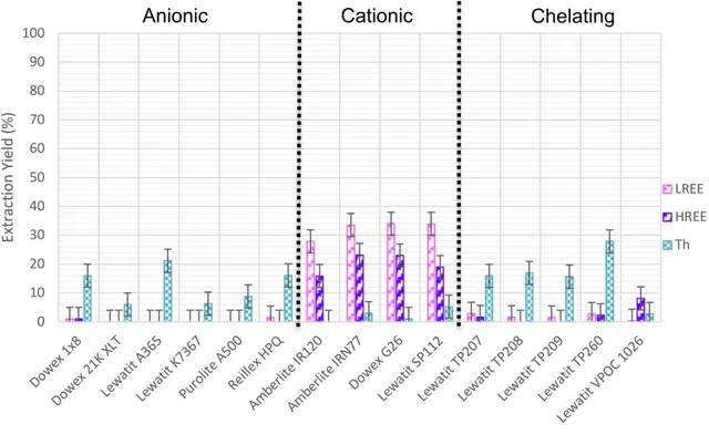
Figure 11 Screening of anionic, cationic and chelating resins with REESL ... 44
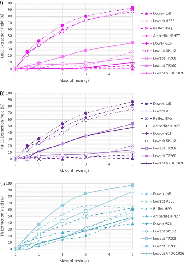
Figure 12 A) LREE, B) HREE, and C) Th capacity of selected resins on REESL ... 47
Figure 13 Capacity of Dowex 1x8 for thorium in 100 mL of REESL for 24h ... 48
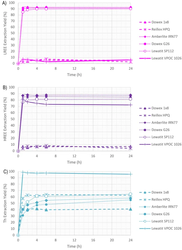
Figure 14 A) LREE, B) HREE, and C) Th kinetics of selected resins on REESL ... 50
Figure 15 REESL RIP Process ... 53
Figure 16 A) Dowex 1x8 and B) Reillex HPQ RIP processes on REESL ... 54
Figure 17 Dowex 1x8 12-mL column uptake on REESL, flow rate of 3 BdV h-1 ... 56
Figure 18 Reillex HPQ 12-mL column uptake on REESL, flow rate of 3 BdV h-1 ... 56
Figure 19 Lewatit VPOC 1026 12-mL column uptake on REESL, flow rate of 3 BdV h-1 ... 57
Figure 20 Lewatit SP112 12-mL column uptake on REESL, flow rate of 3 BdV h-1 ... 58
Figure 21 Screening of anionic, cationic, and chelating resins on REENL ... 60
Figure 22 A) LREE, B) HREE, and C) Th capacity of selected resins on REENL ... 61
Figure 23 A) LREE, B) HREE, and C) Th kinetic of selected resins on REENL ... 63
Figure 24 Lewatit VP OC 1026 12-mL column uptake on REENL, flow rate of 3 BdV h-1 ... 64
Figure 25 Effect of the NaCl concentration for A) uranium and B) mercury on P1 and P2 ... 67
Figure 26 A) Uranium and B) mercury kinetics on P1 from NaCl leachates ... 68
Figure 27 A) Uranium and B) mercury kinetics on P2 from NaCl leachates ... 69
Figure 28 Effect of the KI concentration for A) uranium and B) mercury on P1 and P2 ... 72
Figure 29 A) Uranium and B) mercury kinetics on P1 from KI leachates ... 73
Figure 30 A) Uranium and B) mercury kinetics on P2 from KI leachates ... 74
Figure 31 A) Uranium and B) mercury capacity on Lewatit TP260 from KI leachates ... 77
Figure 32 A) Uranium and B) mercury capacity on Lewatit TP214 from KI leachates ... 80
Figure 33 A) Uranium and B) mercury kinetics on Lewatit TP260 from KI leachates ... 81
Figure 34 A) Uranium and B) mercury kinetics on Lewatit TP214 from KI leachates ... 82
Figure 35 Extraction of A) uranium and B) mercury from different the flow rates using KI 30 on a 12-mL column filled with Lewatit TP260 ... 84
Figure 36 Screening of anionic, cationic, and chelating resins using HEUNLs ... 85
Figure 37 A) Uranium and B) mercury capacity of selected resins on HEUNLs ... 87
Figure 38 Uranium and mercury kinetics of selected resins on HEUNLs ... 88
List of Tables
Table 1 Main factors of mining feasibility studies ... 2
Table 2 List of the 35 critical minerals and their use ... 4
Table 3 Composition of major REE minerals ... 8
Table 4 Formation coefficient of Nd, Er, and Th in sulfate media ... 10
Table 5 Formation coefficient of Nd, Er, and Th in nitrate media ... 11
Table 6 Estimated resources of Canadian REE deposit sites into advanced exploration stage ... 13
Table 7 Stability constants of uranium complexes with common inorganic ligands ... 15
Table 8 Chemical equilibrium of aqueous oxalate ... 24
Table 9 Structural representation of some extractants ... 25
Table 10 Summary of resin types and structures ... 28
Table 11 Structures of popular stripping agents ... 30
Table 12 Overall comparison of the separation techniques ... 33
Table 13 Resin provider information ... 36
Table 14 Composition of the REE leachates ... 37
Table 15 Composition of the different SCRWL ... 39
Table 16 Composition of the HEUNLs ... 40
Table 17 Instrumental parameters of elemental analysis ... 42
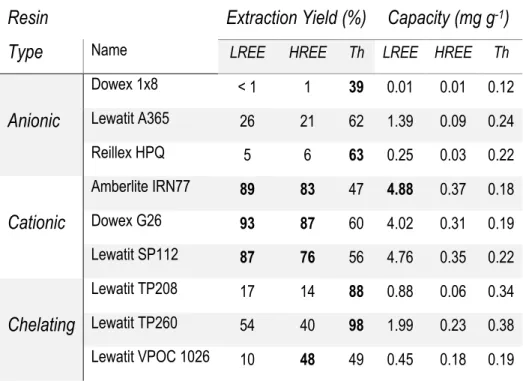
Table 18 Summary of capacity results from a 5 g: 100 mL ratio ... 49
Table 19 Recovery of absorbed metals from loaded resin using different desorption agents ratio 1 mL of agent for 1 g of resin ... 52
List of Abbreviations and Acronyms
Ac Actinides
BdV Bed volume
BdVh-1 Bed volume per hour CANDU Canada deuterium uranium DGA Diglycolamide
FISST Fissile solution storage tank HEU Highly enriched uranium
HEUNL Highly enriched uranyl nitrate liquid
HEUNLs Highly enriched uranyl nitrate liquid surrogate HREE Heavy rare earth
IX Ion exchange
Kf Formation coefficient LREE Light rare earth LEU Low enriched uranium
Ln Lanthanides
N.P. Not provided
NPT Non-Proliferation of nuclear weapons treaty PT Precipitation techniques
PUREX Plutonium uranium redox extraction REE Rare earth element
REENL Rare earth nitric leachate REESL Rare earth sulfuric leachate REO Rare earth oxide
RIP Resin in pulp
SA Strong acid
SB Strong base
SCRW Surrogate cemented radioactive waste
SCRWL Surrogate cemented radioactive waste leachate SX Solvent extraction
WA Weak acid
WB Weak base
À mon cher ami d’enfance,
Patrice Courchesne
1994.04.04 - 2019.08.25
Ce n’est pas aux générations futures
de récolter l’insouciance du passé.
Remerciements
En premier lieu, je tiens à remercier mes codirecteurs de recherche, Nicolas Reynier et Dominic Larivière pour leur patience, leur compréhension et leur dévouement. Vos précieux conseils ont fait de moi un scientifique plus averti.
J’aimerais remercier le Gouvernement du Canada, Ressources naturelles Canada ainsi que CanmetMINES de m’avoir offert cette opportunité de maitrise exceptionnelle. Ce milieu riche en connaissances a contribué à ma formation académique et a grandement facilité ma transition au milieu professionnel.
Merci à mes collègues de travail de Limebank, et plus précisément Cheryl qui m’a prêté main-forte à plusieurs reprises pour diverses expériences et analyses au laboratoire. À Roselyne, mon rayon de soleil, ma chimiste en devenir préférée, merci de m’avoir accompagné au laboratoire avec ton enthousiasme contagieux. Je te souhaite une aventure yukonaise des plus merveilleuses. Un merci spécial à Laurence avec qui j’ai partagé ces deux années de montagnes russes. J’ai découvert en toi un mentor attentionné, une scientifique dévouée ainsi qu’une jeune femme déterminée avec qui je partage maintenant un lien d’amitié profond et sincère. Je te souhaite tout le bonheur du monde dans tes futurs projets états-uniens. Pour terminer, merci à ma famille de m’avoir encouragé et accompagné de la ligne de départ au fil d’arrivée. Sans vous, il m’aurait été difficile de plonger avec aplomb dans cette aventure ottavienne.
Figure 1 Representation of circular economy in the mining field
Introduction
The life cycle of any consumable items starts by the gathering of primary resources followed by production, use and disposal. In many ways, primary resources are the rough versions of any final product. Nowadays, to produce most of modern items and high-technology devices, it seems mandatory to retrieve these primary resources from raw material. However, the continuous extraction of raw material encourages the use and immediate disposal of the material leading to their reckless overconsumption. To remediate the problem, modern economical models, like circular economy, are emerging amidst the increasingly alarming waste production crisis.
Circular economy
The circular economy model offers a responsible way for companies to manage the end-of-life of their products and the way they generate waste. This model was first introduced into environmental policy to promote a sustained economic growth of the raw materials and natural resources field.1 Figure 1 shows an example of circular economy applied to the mining industry.
Typically, primary resources are directly extracted from Earth’s crust. After the exploration stage is completed, where the deposit has been located, the mining stage is initiated. Some primary resources can be challenging to extract, and multiple factors are considered during the mining feasibility study such as geology, ore reserves, mineral processing and environmental considerations (Table 1). Since a mine focuses on the production of a specific metal, the processing stage produces a lot of waste that potentially holds other resources. For example, the processing of 1 tonne of rare earth elements (REE) can produce up to 1.4 tonne of radioactive waste containing thorium.3 With the right process, it would be possible to retrieve thorium and collect it as a by-product, which would maximize the cost-efficiency of mining and processing.
Table 1 Main factors of mining feasibility studies
4Factor Level of geological input
Geology High
Ore reserves High
Environmental considerations Moderate
Mineral processing Moderate
Mining Moderate
Metal extraction Low
Operating costs Low
After processing, the raw materials go through the design and production steps where they are transformed to their commercialized forms. This leads to the use and reuse of the product until its end-of-life. In a linear economic system, the used products would go to waste, but in a circular economy system, the used products would be collected and the raw materials would be recycled. For example, a widely used medical isotope production method only consumes 10% of its product (uranium). In the current linear system, it means that 90% of the unused uranium directly goes to waste. As for the circular economy system, the 90% unused uranium would be recycled, reprocessed and reused. This would not only reduce costs and uranium demand, but also reduce the volume and hazardousness of the waste.
Other recycling methods like urban mining have emerged in the past decade. Urban mining extends landfill mining to the practice of recovering compounds and elements from any kind of anthropogenic merchandise.5 Extraction and processing of anthropogenic merchandise is crucial and economic assessments must be profitable. For these reasons, urban mining originally aimed at electronic wastes, which contain relatively high concentrations of valuable metals like REE.6
Circular economy can prevent accumulation of valuable waste and reduce waste production. The recycling of the used items allows a more efficient way to manage waste and increases its supplies from a different contributing sector. This can be a valuable system to sustain the development of the various technological fields in need of critical minerals.
Critical minerals
In 2018, the United States Geological Survey (USGS) has classified 35 modern minerals as critical. The USGS classifies a mineral as critica7l, when:
- It is identified to be a non-fuel mineral or mineral material essential to the economic and national security of the United States
- Its supply chain is vulnerable to disruption
- It serves an essential function in the manufacturing of a product, the absence of which would have significant consequences for the economy or national security
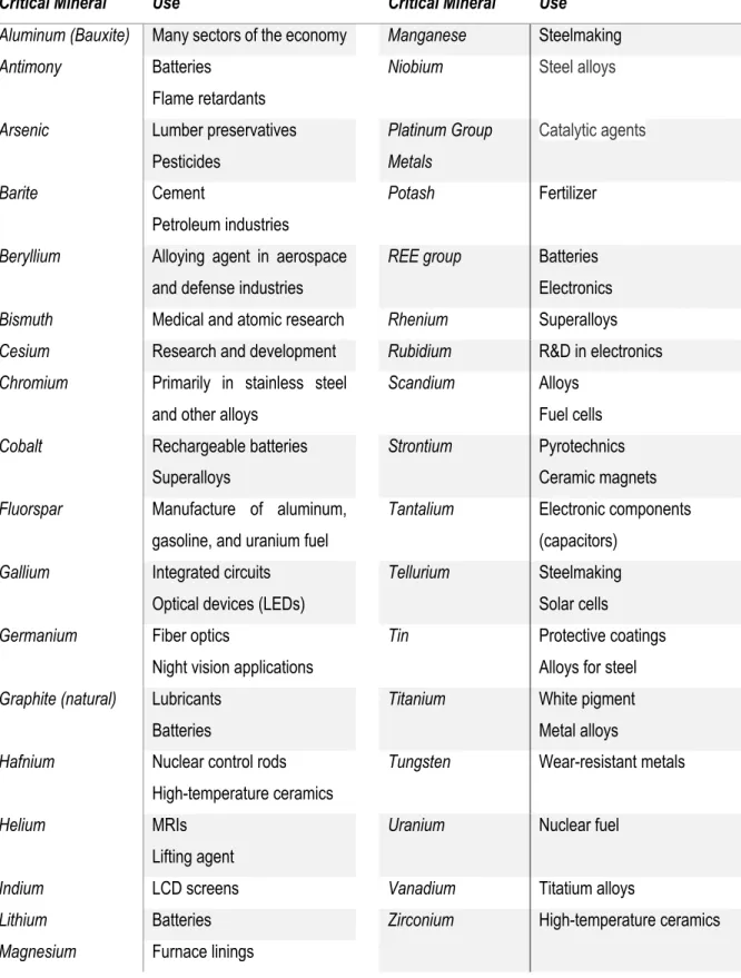
As showed in Table 2, the REE group is classified as critical minerals for its important use in batteries and electronics. Uranium is also classified as a critical mineral for its use as nuclear fuel. In Canada, uranium was also used to produce medical isotopes for nuclear medicine practices. In fact, before it ceased production in October 2016, Chalk River Laboratories provided up to 40% of the worldwide medical isotopes demand.8 From these applications, it is mandatory that a global strategy is established to recover these critical minerals.
Recovery
For both REE and uranium, their recovery can be challenging. Most of REE deposits are found in low concentrations. Even though REE are abundant on Earth, retrieving them means mining a high volume of ore due to their limited presence in the ore. The solubilization of the ore produces a leachate containing a low concentration of REE. Therefore, the processing of the leachate must be adapted to a low concentration of REE and a high concentration of other metals, like iron, silica, and calcium. In addition, actinides, like thorium, contained in the ore must be separated from the leachate. As for the uranium, the production of medical isotope produces waste that contains many different fission products and other metals like aluminum and mercury. The presence of these metals involves a higher level of complexity to recover uranium selectively.
In both REE and uranium cases, working with complex matrices is the main challenge. Research is still ongoing to enhance the efficiency of modern processes to recover REE and uranium.
Table 2 List of the 35 critical minerals and their use
9Critical Mineral Use Critical Mineral Use
Aluminum (Bauxite) Many sectors of the economy Manganese Steelmaking Antimony Batteries
Flame retardants
Niobium Steel alloys
Arsenic Lumber preservatives Pesticides Platinum Group Metals Catalytic agents Barite Cement Petroleum industries Potash Fertilizer
Beryllium Alloying agent in aerospace and defense industries
REE group Batteries Electronics Bismuth Medical and atomic research Rhenium Superalloys Cesium Research and development Rubidium R&D in electronics Chromium Primarily in stainless steel
and other alloys
Scandium Alloys
Fuel cells Cobalt Rechargeable batteries
Superalloys
Strontium Pyrotechnics Ceramic magnets Fluorspar Manufacture of aluminum,
gasoline, and uranium fuel
Tantalium Electronic components (capacitors)
Gallium Integrated circuits Optical devices (LEDs)
Tellurium Steelmaking Solar cells Germanium Fiber optics
Night vision applications
Tin Protective coatings
Alloys for steel Graphite (natural) Lubricants
Batteries
Titanium White pigment Metal alloys Hafnium Nuclear control rods
High-temperature ceramics
Tungsten Wear-resistant metals
Helium MRIs
Lifting agent
Uranium Nuclear fuel
Indium LCD screens Vanadium Titatium alloys
Lithium Batteries Zirconium High-temperature ceramics
Proposition
This thesis explores new alternatives using chromatographic resins to enable the commercial extraction of critical minerals in a circular economy perspective. To this end, experiments were carried out to investigate the suitability of ion exchange to separate thorium and REE from industrial REE leachate and retrieve uranium from medical isotope production waste. Sulfate media and nitrate media were tested in both projects. For each solution, preliminary processes were designed, tested and selected for their commercialisation potential.
Chapter 1 The Lanthanides and Actinides
The problematics addressed in this thesis involve two series of chemical elements: the lanthanides group, also known as the REE, and the actinides group, which includes thorium and uranium. To get a better understanding of the topic, this chapter describes these elements, their chemistry and their modern challenges.
1.1 The rare earth elements and the mining industry
The 15 elements present in the lanthanides group (Ln) row of the periodic table are commonly called the Rare Earth Elements group (REE). In addition, yttrium and scandium have been included to the REE due to their similar properties.10 They are often subdivided into two categories: the Light Rare Earth Elements group (LREE) and the Heavy Rare Earth Elements group (HREE). LREE includes elements from lanthanum to europium and scandium, whereas HREE includes elements from gadolinium to lutetium and yttrium.
The ionic radius of Ln decreases as the proton number (Z) increases. This effect, known as the lanthanide contraction, is due to the electronic configuration of their oxidation state (Ln3+). The trivalent oxidation state is shared by all Ln and originates from their common electronic configuration [Xe] 6s24fx5dy, where y = (Z-56)-x. Through oxidation, Ln lose both electrons contained in the 6s orbital and one in the 4f or 5d orbital. By losing both electrons from the 6s orbital, electrons from the 4f and 5d are more attracted to the nucleus, losing the shielding effect induced by the 6s orbital. Shielding effect is described as the capacity of lower energy orbitals to shield the nucleus attraction to higher energy orbitals. The relative shielding strength between atomic orbitals is described as s>p>d>f. In addition to the decrease of the shielding effect, as Z increases, the attraction of the nucleus increases as well, leading to the synergetic attraction of the electrons in the 4f and 5d orbitals. By being closer to the nucleus, the electron density increases near the nucleus, making the atom’s radius smaller. It is observed that the coordination number of Ln decreases with the size of the anion.11
To increase stability through symmetrical electronic configuration, some Ln reach divalent and tetravalent oxidation states. Stable Ce4+ occurs by completely removing electrons contained in its 4f orbital, leading to a symmetrical electronic configuration, [Xe]4f0 or [Xe]. Eu2+ and Tb4+ acquire symmetrical electronic configurations with partially-filled 4f orbitals. This induces stability of their respective oxidation states, [Xe]4f7. Tb2+ achieves a symmetrical electronic configuration when the 4f orbital is completely filled, [Xe]4f14. For Sm2+ and Tm2+, the symmetrical electronic configuration of partially-filled orbital 4f is not achieved by missing one electron, but the divalent state is still observed. However, Sm2+ and Tm2+ electronic configurations are unstable and the ions tend to oxidize readily.11 The diverse electronic configurations of the REE allows them to bond with different anions like carbonate, fluoride and phosphate to form various minerals, the REE ores.
1.1.1 REE Ores
Rare earth elements mostly occur as ores present in the Earth’s crust. The most used minerals for Rare Earth Oxide (REO) production include monazite, bastnaesite and xenotime, Table 3.12 Cerium and lanthanum are the most common elements in those ores, but are sometimes substituted in the mineral lattice by heavier REE.13 Actinides, like thorium and uranium, are also found to substitute REE in the ore’s mineral lattice.14 In addition to their undesired presence from a hydrometallurgical perspective, these actinides induce radioactivity in the mineral.15 Therefore, their chemical properties must be understood to limit contamination of REO final products. In this thesis, thorium was selected for analysis over uranium due to its higher presence in the studied solutions.
Table 3 Composition of major REE minerals
161.1.1.1 Ore processing
Unlike gold, REE minerals are found in low concentrations and are dispersed through the soil. After mining, the ore obtained is subjected to a processing step where REE are extracted from the solid matrix. This processing step can include separation of the crushed ore particles to concentrate the ore (flotation) and selective solubilization of the ore (leaching). The processes involved will be described in the next sub-sections.
1.1.1.1.1 Flotation
Flotation is the most commonly used method for the beneficiation of REE minerals.17 The ore is grounded to a specific particle size and mixed with various flotation agents. By choosing the correct agent, it is possible to selectively separate REE-bearing particles from the gangue. Selected particles are floated to the surface of the tank by a foam made of collector agents. Depressant agents are added to remove unwanted gangue from the foam. This allows the foam to specifically contain particles bearing REE minerals. To do so, flotation techniques uses various hydroxamic and fatty acids as collectors, and sodium fluosilicate and alum as depressants.18 After flotation, the concentrated ore particles go through a selective solubilization where the REE are solubilized from their mineral form.
REE Ore Type Chemical composition
Bastnaesite Fluorocarbonate (Ce, La)(CO3)F
Monazite Phosphate (Ce, La)PO4
1.1.1.1.2 Leaching
Conventional leaching uses concentrated acid to perform extraction on the ore. During the process, a chosen acid is combined with the ore. Acids such as sulfuric, nitric, and hydrochloric acid are frequently used. 19, 20 In sulfate media, Ce can be found in mono, di and tri sulfato complexes.21 From Eu(III) stability constant experiments, it was calculated that concentration ratios of LnSO4+ and Ln(SO4)2- over Ln3+ are 10.3 and 3.9, respectively.22 In nitrate media, Ln can be found as Ln(NO3)63-. For cerium, it is noted that Ce(NO3)4 and Ce(NO3)62- complexes exist in excess of nitrate.23 Since thorium also composes the ore, it is also leached. To minimize the leaching of thorium, parameters like the temperature, the nature of the leaching agent and its concentration are meticulously selected.
In the acid bake process, the ore collected from the mining sites is “baked” at high temperature in concentrated acid. During this process, the ore is attacked and targeted elements are solubilized. In sulfuric acid media, concentration of the acid and temperature can easily reach 98% and 200°C to 230°C, respectively. 24 The equations below show the leaching of monazite containing Th.
2 (𝑅𝐸𝐸)𝑃𝑂)(*)+ 3 𝐻.𝑆𝑂)(01)→ (𝑅𝐸𝐸).(𝑆𝑂))3(*)+ 6𝐻5+ 2 𝑃𝑂) 36
Equation 1
𝑇ℎ3(𝑃𝑂)))(*)+ 6 𝐻.𝑆𝑂)(01)→ 3 𝑇ℎ(𝑆𝑂)).(*)+ 12 𝐻5+ 4𝑃𝑂 )36Equation 2
To solubilize solid sulfates, water is added at a 1:7 ratio.
(𝑅𝐸𝐸).(𝑆𝑂))3(*)+ 𝑛𝐻.𝑂 → 2(𝑅𝐸𝐸)35+ 3𝑆𝑂 ).6
Equation 3
𝑇ℎ(𝑆𝑂)).(*) → 𝑇ℎ)5+ 2𝑆𝑂 ).6Equation 4
Table 4 shows the affinity of Nd, Er and Th to form various sulfate complexes. It is shown from their log Kf, where Kf represents the formation coefficient of the complex, that most REE will stay in cationic form whereas thorium will tend to form Th(SO4)32- anionic complexes.
Figure 2 Eh-pH diagrams for Th-, Nd-, Ce-, La-SO
4-H
2O system at 25°C [M]=0.01M and [SO
42-]=0.1M
Table 4 Formation coefficient of Nd, Er, and Th in sulfate media
25 26Metal Equilibrium log Kf
Nd Nd 3+ + SO42- ↔ Nd(SO4)+ 3.65 Nd(SO4)+ + SO42- ↔ Nd(SO4)2- 1.50 Er Er 3+ + SO42- ↔ Er(SO4)+ 3.59 Er(SO4)+ + SO42- ↔ Er(SO4)2- 1.61 Th Th4+ + SO42- ↔ Th(SO4)2+ 5.45 Th(SO4)2+ + SO42- ↔ Th(SO4)2 9.73 Th(SO4)2 + SO42- ↔ Th(SO4)32- 10.5 Th(SO4)32- + SO42- ↔ Th(SO4)44- 8.48
Eh-pH diagrams (Fig 2) suggest that, at a metal concentration of 0.01 M, a sulfate concentration of 0.1 M and pH 2, the metals form complexes of Th(SO4)2, Nd2(SO4)3•8H2O, CeSO4+ and La2(SO4)3•9H2O with sulfates. These species are in close equilibrium with their other cationic complexes containing different numbers of coordinated sulfates.
For nitric acid, temperatures from 180°C to 220°C allow a recovery up to 90% of REE from monazite. Using nitric acid at high temperature also minimizes iron and phosphorus concentration in the leachate due to the formation of solid hydroxyferric phosphates.27
𝐿𝑛𝑃𝑂)+ 5 8𝐹𝑒.𝑂3+ 3𝐻𝑁𝑂3→ 𝐿𝑛(𝑁𝑂3)3+ 1 4𝐹𝑒B(𝑃𝑂)))(𝑂𝐻)3•2𝐻.𝑂 + 17 8 𝐻.𝑂
Equation 5
Mono and divalent Th(IV) nitrate complexes can be described as [Th(NO3)5]- and [Th(NO3)6]2-. Monovalent complexes include ATh(NO3)5•xH2O, where A=NH4, Na or K. The divalent complexes can take the form of A2Th(NO3)6 and BTh(NO3)6•8H2O, where B=Mg, Mn, Co, Ni, Zn.28 From Table 5 formation coefficients, it is possible to estimate that Nd, Er and thorium will be found as cationic complexes in the nitrate media.
Table 5 Formation coefficient of Nd, Er, and Th in nitrate media
2930Metal Equilibre log Kf
Nd Nd3+ + NO3- ↔ Nd(NO3)2+ 1.25
Er Er3+ + NO3- ↔ Er(NO3)2+ 0.74
Th Th
4+ + NO3- ↔ Th(NO3)3+ 0.94 Th(NO3)3+ + NO3- ↔ Th(NO3)22+ 1.97
Alkaline leaching is also used to process REE mineral ores. This leaching step usually aims to remove thorium and uranium present in the mineral lattice. Carbonate leaching focuses on the high affinity of these actinide-carbonate complexes to selectively remove actinides from the mineral.31 Since alkaline agents are not as aggressive on the mineral lattice as acidic agents, smaller particle sizes must be used to increase the surface area of the mineral with the leaching agent. For monazite, a phosphate mineral, thorium content is higher and is not desired in the leachate. Therefore, an alkaline leaching helps minimalize thorium leaching. The solid thorium hydroxides can then be selectively solubilized and removed from further steps.28
(𝑅𝐸𝐸)𝑃𝑂)+ 3𝑁𝑎𝑂𝐻 → (𝑅𝐸𝐸)(𝑂𝐻)3+ 𝑁𝑎3𝑃𝑂)
Equation 6
𝑇ℎ3(𝑃𝑂)))+ 12𝑁𝑎𝑂𝐻 → 3 𝑇ℎ(𝑂𝐻))+ 4 𝑁𝑎3𝑃𝑂)
This way, it is possible to combine alkaline and acid leaching in order to achieve a selective leaching of REE. For example, a two-step leaching process was developed to first leach uranium during the alkaline leaching and an acid leaching without uranium for further extraction.32 This method was also used to selectively extract REE fluorides in bastnaesite, a fluorocarbonate mineral:
(𝑅𝐸𝐸)𝐹3− (𝑅𝐸𝐸).(𝐶𝑂3)3+ 9 𝐻𝐶𝑙 ⟶ (𝑅𝐸𝐸)𝐹3+ 3𝐻𝐶𝑙 + 3𝐻.𝑂 + 3𝐶𝑂.
Equation 8
(𝑅𝐸𝐸)𝐹3+ 3𝑁𝑎𝑂𝐻 ⟶ (𝑅𝐸𝐸)(𝑂𝐻)3+ 3𝑁𝑎Equation 9
(𝑅𝐸𝐸)(𝑂𝐻)3+ 3𝐻𝐶𝑙 → (𝑅𝐸𝐸)𝐶𝑙3+ 3𝐻.𝑂Equation 10
1.1.3 Problematic REE in Canada
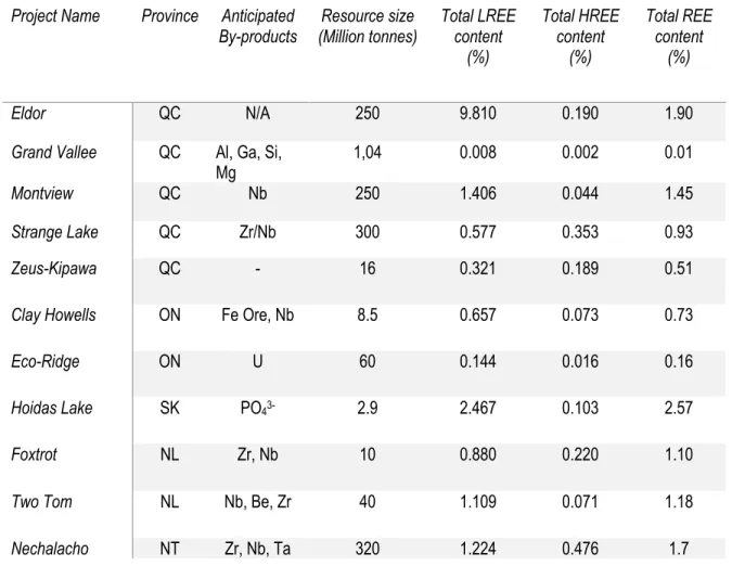
As the production of technological devices increases, so does the demand for REE. Therefore, there is a vast economic opportunity to seize as the REE market expands. Canada is reputed to possess approximatively 40 to 50% of the world’s REE reserves.34 In 2013, eleven REE projects were classified as in “advanced exploration stage” (Table 6). Such classification indicates that the mining project has reached drilling, trenching, preliminary metallurgy, and deposit delineation related activities.33 A majority of those projects are located in the province of Quebec. This province also hosts two deposits (Strange Lake and Zeus-Kipawa) that are enriched in HREE.34 Typically, HREE are less abundant than LREE. These deposits have strong economic potential despite their relatively low REE contents.35
34
Table 6 Estimated resources of Canadian REE deposit sites into advanced exploration stage
QC-Québec ON-Ontario SK-Saskatchewan NL-Newfoundland and Labrador NT-Northwest territories
Canada is on the brink of developing its own REE production. With large REE reserves, the exploitation must be considered while the demand is still present. Therefore, Canada is conducting research and investigations to develop its own REE production technology. From extraction to purification, this technology must involve efficient methods to retrieve REE and carefully manage the environmental issues of REE production. The first part of this thesis investigates the use of ion exchange to efficiently purify REE mineral leachates by selectively removing thorium to recover REE.
Project Name Province Anticipated
By-products (Million tonnes) Resource size Total LREE content (%) Total HREE content (%) Total REE content (%) Eldor QC N/A 250 9.810 0.190 1.90
Grand Vallee QC Al, Ga, Si,
Mg 1,04 0.008 0.002 0.01
Montview QC Nb 250 1.406 0.044 1.45
Strange Lake QC Zr/Nb 300 0.577 0.353 0.93
Zeus-Kipawa QC - 16 0.321 0.189 0.51
Clay Howells ON Fe Ore, Nb 8.5 0.657 0.073 0.73
Eco-Ridge ON U 60 0.144 0.016 0.16
Hoidas Lake SK PO43- 2.9 2.467 0.103 2.57
Foxtrot NL Zr, Nb 10 0.880 0.220 1.10
Two Tom NL Nb, Be, Zr 40 1.109 0.071 1.18
1.2 Uranium and the nuclear industry
Uranium is an ubiquitous part of the Earth since its very own formation. Considered as a major actinide with thorium, uranium is one of the most abundant elements of the actinides family.36 In natural environment, uranium oxidation states are U(IV) and U(VI). Through all oxidation states, uranium is a strong Lewis acid and hard electron acceptor. These properties allow uranium to exert a strong inductive effect on the coordinated ligands.
1.2.1 Uranium inorganic complexes
Like most metals, uranium has the ability to coordinate itself with various types of ligands including inorganic ligands. In acidic conditions (pH <4 and a redox potential of over 0.5 V), the uranyl form (UO22+) is the dominating species in absence of other ionic species other than H+ and OH- (Fig 3).
From their stability constants (logbn) in non-complexing media, uranyl sulfate complexes, UO2SO4 (3.15) and UO2(SO4)22- (4.14), are more stable than uranyl nitrate UO2NO3+ (0.3) and uranyl chloride complexes, UO2Cl+ (0.17) and UO2Cl2 (-1.1) (Table 7). Stability constants also suggests that UO2(SO4)22- is more stable than UO2SO4. Data on uranyl nitrate complexes must be retrieved to compare stability of its polynitrate forms. Carbonate complexes, UO2CO3 (9.68), UO2(CO3)22- (16.9), and UO2(CO3)34- (21.6), show the highest stability constants with UO22+ over sulfate, nitrate and chloride. The uranyl tricarbonate ion, UO2(CO3)34-, is a very stable ion at low hydroxide ion concentration. An increase of hydroxide ions in the carbonate-uranium solution will induce precipitation of uranates.28
Table 7 Stability constants of uranium complexes with common inorganic ligands
at zero ionic strength at 25°C
28Chemical equilibrium 𝒍𝒐𝒈 𝜷𝒏 𝑈𝑂..5+ 𝐶𝑙6 ⇌ 𝑈𝑂 .𝐶𝑙5 0.17 𝑈𝑂..5+ 2𝐶𝑙6 ⇌ 𝑈𝑂 .𝐶𝑙. -1.1 𝑈𝑂..5+ 𝑁𝑂 36⇌ 𝑈𝑂.𝑁𝑂35 0.3 𝑈𝑂..5+ 𝑆𝑂 ).6⇌ 𝑈𝑂.𝑆𝑂) 3.15 𝑈𝑂..5+ 2𝑆𝑂 ).6⇌ 𝑈𝑂.(𝑆𝑂))..6 4.14 𝑈𝑂..5+ 𝐶𝑂 3.6⇌ 𝑈𝑂.𝐶𝑂3 9.68 𝑈𝑂..5+ 2𝐶𝑂 3.6⇌ 𝑈𝑂.(𝐶𝑂3)..6 16.9 𝑈𝑂..5+ 3𝐶𝑂 3.6⇌ 𝑈𝑂.(𝐶𝑂3)3)6 21.6
1.2.2 Uranium isotopes
Uranium is composed of three naturally-occurring isotopes,234U, 235U, and 238U, which are all radioactive. Their relative isotopic abundance are 0.0055, 0.72 and 99.27%, respectively. Although 238U is the most naturally abundant isotope, 235U is the most coveted one. The reason for its covetousness lies in its fissile property. Uranium-235 is able to enter nuclear fission in the presence of thermal neutrons and generate a great amount of energy (Fig. 4). Nuclear fission was largely studied during the Manhattan Project for its promising applications. Compared to chemical reactions, nuclear reactions are known to release amongst the largest amounts of energy per gram of fuel. For example, it is estimated that for the same mass, the amount of energy released from 235U fission reaction would be three million times bigger than a coal combustion reaction.38 However, its low abundance makes it harder to retrieve and purify from the other isotopes.
Figure 4 Schematic representation of
235U fission process
391.2.2.1 Isotopic enrichment
While being the most valuable isotope of uranium, 235U is present at a very low isotopic abundance due to its relatively short half-life (t1/2=703.8x106 y) compared to 238U (t1/2=4.5x109 y). The half-life of a radioisotope is defined as the period of time required for half of the isotope population to decay. Thus, most of the 235U present on Earth has since decayed into 231Th. For this reason, enrichment of 235U content up to a few percent is frequently performed via refining. Due to their identical chemical properties, isotopic enrichment of 235U from 238U is challenging. Since the only difference between these isotopes is their mass, mass separation is the most effective technique to pursue isotopic enrichment. This is typically performed by centrifugation of gaseous uranium as UF6.
𝑈𝑂.+ 4 𝐻𝐹 ⟶ 𝑈𝐹)+ 2 𝐻.𝑂
Equation 11
𝑈𝐹)+ 𝐹.⟶ 𝑈𝐹Q
Equation 12
After multiple centrifugation cycles, the enriched uranium-235 gas is converted back to a solid state as UO2.40
𝑈𝐹Q+ 2 𝐻.𝑂 ⟶ 𝑈𝑂.𝐹.+ 4𝐻𝐹
Equation 13
𝑈𝑂.𝐹.+ 𝐻.⟶ 𝑈𝑂.+ 2𝐻𝐹
The isotopic enrichment represents the degree of isotopic alteration of two isotopes, in this case 235U and 238U. Uranium enrichment is defined as 235U/238U and is expressed in %.
Figure 5 Uranium enrichment process
41Different grades of uranium can be obtained from this enrichment process: low-enriched uranium (LEU) and highly enriched uranium (HEU) in which the isotopic enrichment are below and above 20%, respectively. Furthermore, when the isotopic enrichment exceeds 90%, the material is categorized as weapon grade. 42, 43, 44 The degree of enrichment usually determines the application of the fissile material.
1.2.3 Applications
1.2.3.1 Nuclear Power
Energy production is a critical issue in modern life as energy consumption keeps increasing. Many countries depend on the production of electricity via fossil fuels, hydroelectricity, geothermal, wind turbine, photovoltaic systems, and nuclear power. However, these resources can be unavailable in a specific geographical location, which could limit the diversity of energy sources available. For example, large water basins are required for the production of hydroelectricity, and a minimal wind velocity is required to achieve a profitable wind turbine production. Canada is a poster child for the diversity of its energetic portfolio, which is very distinctive for most provinces (Fig. 6).
Figure 6 Energy production of some Canadian provinces
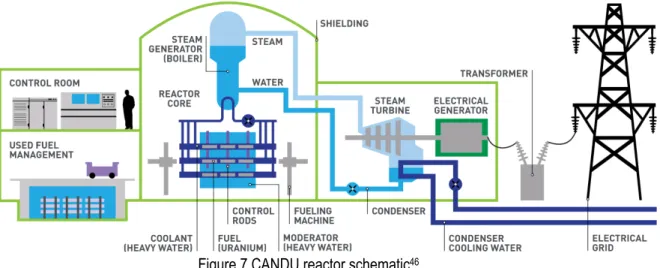
While the use of renewable energy is growing worldwide, Canada still relies significantly on non-reusable resources such as fossil fuel and nuclear power. Fossil fuel is strongly criticized by ecologists since it releases harmful combustion products in the environment while increasing the amount of CO2 in the atmosphere. Meanwhile, nuclear power offers a greener alternative to produce electricity compared to fossil fuel.45 Instead of using combustion reactions, nuclear power plants use the energy released during nuclear rearrangement to produce heat. Canada was a nuclear pioneer by designing the Canada Deuterium Uranium (CANDU) reactor (Fig. 7). Today, CANDU reactors are used around the world. The principle of this reactor has similarities to any other electricity generator. The energy coming from the fission process acts as any other heat source. The heat produced by the fuel, the uranium rods, inside the reactor core is absorbed by water in the steam generator. The steamed produced will activate the steam turbine and generate electricity. The steam is cooled and condensed to its liquid form to be reused. The CANDU reactor only requires natural uranium, whereas the type of reactor used to produce medical isotopes requires HEU.
Figure 7 CANDU reactor schematic46
1.2.3.2 Medical Isotopes
One of the most common medical imaging techniques requires 99mTc, an unstable and radioactive isotope of Tc. This particular isotope is used in nuclear medicine, because it emits gamma rays during its nuclear rearrangement into its most stable form, 99Tc (Fig. 8.).
Figure 8
99Mo disintegration scheme
47Metastable technetium-99 is obtained by the nuclear rearrangement of 99Mo via b- decay. While naturally occurring, molybdenum has seven isotopes and 99Mo is not one of them due to its radioactive nature. However, 99Mo is produced, with a multitude of other radioisotopes, when 235U nuclei are fissioned (Fig. 9).
Figure 9
235U Fission products (u)
48To synthetically produce molybdenum-99, highly enriched uranium is chemically combined with aluminium to form an alloy which is manufactured as rods. These rods are placed into a fission reactor to be bombarded by neutrons. When 99Mo production and disintegration rates reach equilibrium, the rods are removed from the reactor and solubilized in nitric acid. Mercury nitrate is usually added to the nitric acid solution to accelerate solubilization.49 Ion exchange separation is then performed to isolate 99Mo from the acidic matrix. It is estimated that more than 90% of the original 235U content is still present in the rod after the fission process.50 Thus, the waste produced from such a process contains a high concentration of 235U, numerous fission products, aluminum, and mercury.51
1.2.4 Disposal
As mentioned previously, the use of 235U leaves a number of hazardous components in the waste. Therefore, proper waste management is essential to ensure a safe disposal of these radioactive wastes. Waste management strategies include recycling and storing radioactive material as a liquid or solid.
1.2.4.1 Recycling
Recycling HEU spent fuel is an economical strategy to minimize hasty disposal of 235U. The aim of a recycling system is to recover as much 235U as possible from its fission products and produce HEU fuel that could be reused for further medical isotope production cycles. Facilities within nuclear power plants are constantly improving their recycling processes to maximize spent fuel utility.52 As an example, the Plutonium Uranium Redox EXtraction (PUREX) method is used to recycle uranium spent fuel from nuclear power plants.53 If no recycling process is developed or no financial benefits are involved, the solution is stored.
0,00 1,00 2,00 3,00 4,00 5,00 6,00 7,00 8,00 70 80 90 100 110 120 130 140 150 160 The rm al Fi ssi on Yi el d (% p er fi ss io n of 23 5U )
Fission Product Atomic Mass
1.2.4.2 Liquid storage
Liquid state radioactive waste can be stored using a safe storage system that is capable of handling chemicals and radioactivity over an extended period of time. Canada’s Fissile Solution Storage Tank (FISST) is an example of a liquid waste storage system. Located near Chalk River, this double-walled stainless-steel tank offers storage for highly enriched uranyl nitrate liquid (HEUNL). In 2003, the FISST reached its maximal capacity and is tightly monitored. Since then, HEUNL has been cemented and stored as solid waste.
1.2.4.3 Cementation
Liquid wastes are challenging to isolate from the environment as leakage can occur. Thus, it is possible to solidify the nuclear liquid wastes using cementation methods. Cementation offers a good strategy to minimize leakage and increases stability of the waste over time.
Conventional cement, referred to as Portland cement, is used for any typical cementation applications. The composition of the Portland cement includes tricalcium silicate (3CaO•SiO2), dicalcium silicate (2CaO•SiO2), tricalcium aluminate (3CaO•Al2O3) and tetracalcium aluminoferrite (4CaO•Al2O3•Fe2O3). During cementation, water reacts with the cement and forms various hydrates and lime. The overall hydration reaction of the cement is described as exothermic and can be summarized as below:
2 (2𝐶𝑎𝑂•Si𝑂.) + 4𝐻.𝑂 → 3𝐶𝑎𝑂•2Si𝑂.•3𝐻.𝑂 + 𝐶𝑎(𝑂𝐻). (X) 2 (3𝐶𝑎𝑂•Si𝑂.) + 6𝐻.𝑂 → 5𝐶𝑎𝑂•2Si𝑂.•5𝐻.𝑂 + 𝐶𝑎(𝑂𝐻). (X) (3𝐶𝑎𝑂•𝐴𝑙.𝑂3) + 6𝐻.𝑂 → 3𝐶𝑎𝑂•𝐴𝑙.𝑂3•6𝐻.𝑂 (X)
From a radioactive waste management perspective, cementation is an efficient way to confine hazardous material. However, a few challenges are encountered during the cementation process, such as the limited handling of the materials, the temperature control and the chemical composition of the hazardous solution. Since the radioactive material is handled in hot cells, the steps involved in the cementation process must be minimized. The temperature of the solution containing the radioactive material is typically around 90°C at the time of cementation. This relatively high temperature accelerates cement hydration, which may form shells made of hardened cemented paste that may block water from accessing the inner dry cement particles. This could result in a large proportion of non-hydrated cement particles at the end of the cementation process. The composition of the solution also accelerates the hydration of the cement. The high aluminum nitrate content of the solution may have an effect on cement hydration similar to that of the high temperature. To prevent the effects of those factors, both the solution and the cement are poured simultaneously into the designated
container as a continuous stream. This allows some mixing of the solution with dry cement, thus improving the homogeneity of the cemented waste and reducing the formation of hardened cemented paste barriers that could prevent cement hydration. Once the cemented waste has settled it can be safely stored underground.54, 55 This cementation process has been used by Chalk River Laboratories since the mid-1950’s.56 Since then, the cemented wastes containing unused 235U have been stored dormant underground.
1.2.5 HEU repatriation
In 1968, the Non-Proliferation of Nuclear Weapons Treaty (NPT) opened for signatures. Extended indefinitely, the NPT’s objectives are to prevent the spread of nuclear weapons and weapons technology, promote cooperation in the peaceful uses of nuclear energy, and further the goal of achieving nuclear disarmament, general and complete disarmament.57 In April 2010, following the NPT’s decree, Prime Minister of Canada Stephen Harper and President of the United States Barack Obama, agreed to repatriate any HEU stored on Canadian soil.
For many years, Chalk River Laboratories used HEU to produce medical isotopes. Therefore, in Canada, most of the HEU is located in Chalk River Laboratories’ storage sites as aqueous uranyl nitrate and solid cemented waste. To ensure a safe return of the HEU to the United States, separation and purification of the HEU from HEUNL and HEU cemented waste as yellow cake must be done. This would allow the transportation of a highly hazardous material by reducing its volume and improving its management issues. Such a process would require acid leaching (on solid material), and separation of uranium from the acid matrix and precipitation as yellow cake. The second part of this thesis focuses on the separation uranium from surrogate HEUL (HEULs) and surrogate cemented waste leachate (SCWL).
Chapter 2 Separation and Purification Techniques
of the REE and Uranium
As mentioned in the previous chapter, the separation and the purification of critical metals, like the REE and uranium, from complex matrices are still a challenge. This chapter overviews three techniques that are currently used by the industry to separate and purify these metals from complex matrices: precipitation, solvent extraction and ion exchange.
2.1 Precipitation
Precipitation techniques (PT) focus on the solubility of salts present in a solution. It aims to form insoluble salts with a targeted element to easily retrieve it from the solution. One of the main challenges of this technique is the presence of other ions in the solution. A high concentration of some ions (Fe3+, Al3+, Mg2+, Ca2+) can compete with the formation of the precipitate and consume a part of the precipitating agents added to the solution, like in complex pregnant solutions. REE and uranium possess different precipitation properties that allow their recovery.
2.1.1 REE
The recovery of REE can be accomplished through selective precipitation. Mining companies such as Quest Rare Minerals and Search Minerals use a PT through their purification process.
2.1.1.1 Sodium sulfate
PT of REE include the use of sodium sulfate to generate a sodium double sulfate REE complex:
𝑁𝑎5
(UV)+ 𝑅𝐸𝐸35(UV)+ 2 𝑆𝑂).6(UV)+ 𝑥 𝐻.𝑂 ⇌ 𝑁𝑎𝑅𝐸𝐸(𝑆𝑂)).∙ 𝑥 𝐻.𝑂(Y)
Equation 15
Since this complex tends to precipitate in acidic media, an excess of sodium sulfate induces near-complete precipitation of REE. It is also possible to add sodium hydroxide to generate the REE hydroxide form through a metathetic reaction.58
𝑁𝑎𝑅𝐸𝐸(𝑆𝑂)).•𝑥𝐻.𝑂 + 3 𝑁𝑎𝑂𝐻 ⇌ 𝑅𝐸𝐸(𝑂𝐻)3+ 2 𝑁𝑎.𝑆𝑂)+ 𝑥 𝐻.𝑂
2.1.1.2 Oxalate
Oxalate (C2O42-) bearing agents are widely used in the industry due to their low cost and high efficiency.59 According to their speciation, these agents form various complexes with REE. As oxalic acid is a polyprotic acid, it has two pKa values: from oxalic acid (H2C2O4) to hydrogen oxalate (HC2O4-), pK1 1.27, and from hydrogen oxalate (HC2O4-) to oxalate (C2O42-), pK2 4.27 (Table 8).
Table 8 Chemical equilibrium of aqueous oxalate
pK
1Equilibrium
pK
2Equilibrium
Oxalate 1.27 H2C2O3 HC2O4 -+H+ 4.27 HC2O4 - C2O42-+H+
In acidic media, precipitation of REE with oxalic acid occurs as follow: 60
2 𝑅𝐸𝐸35
(UV)+ 3 𝐻.𝐶.𝑂)(UV)+ 𝑥 𝐻.𝑂 ⇌ 𝑅𝐸𝐸.(𝐶.𝑂))3•𝑥 𝐻.𝑂(Y)+ 6𝐻5
Equation 17
2.1.2 Uranium
From uranium trisulphate ([𝑈𝑂.(𝑆𝑂))3])6) to uranium tricarbonate ([𝑈𝑂.(𝐶𝑂3)3])6), uranium can be found
in multiple soluble forms. Three different agents are commonly used to precipitate soluble uranium complexes and produce yellow cake: sodium hydroxide, ammonium hydroxide, and hydrogen peroxide.
2.1.2.1 Sodium hydroxide
Using sodium hydroxide (NaOH) at pH 12 induces the precipitation of soluble uranium complexes into a sodium diuranate compound. This method produces a darker shade of yellow cake. It is used when the pH of the solution is initially alkaline.61
2 [𝑈𝑂.(𝐶𝑂3)3])6+ 14 𝑁𝑎𝑂𝐻 ⟶ 𝑁𝑎.𝑈.𝑂\+ 6 𝑁𝑎.𝐶𝑂3+ 7𝐻.𝑂
Equation 18
2.1.2.2 Ammonium hydroxide
Ammonium hydroxide (NH4OH) precipitation produces a light yellow precipitate made of ammonium diuranate. Precipitation occurs at pH around 7.
2.1.2.3 Hydrogen peroxide
The addition of hydrogen peroxide (H2O2) at a pH of 3.5 produces a uranium peroxide hydrate precipitate. This method is used when the pH of the solution is initially acidic.62
𝑈𝑂.𝑆𝑂)+ 𝐻.𝑂.+ 2𝐻.𝑂 ⟶ 𝑈𝑂3(𝐻.𝑂.)•𝐻.𝑂 + 𝐻.𝑆𝑂)
2.2 Solvent Extraction
Solvent extraction (SX) is a method that uses the basics of liquid-liquid extraction. Organic ligands that act as extractants are mixed into a selected organic phase. If wisely selected, these organic compounds may help to selectively separate desired metals from matrix constituents. Due to the high selectivity of the ligands, SX products contain less impurities than precipitation techniques.63 The use of SX is recommended in solutions containing high concentrations of the elements of interest.64 SX has proven its versatility in various media such as nitric acid, sulfuric acid, and hydrochloric acid.65,66,67
There is a large number of possible extractants that have been used in SX. Popular compounds can be categorised as diglycolamide (DGA), N-donor, and acidic phosphorus compounds. The most commonly use DGA analogs are DODGAA and TODGA.68,69 As for the N-donors, BTP and dipicolinamide offer a great alternative as extractants.70,71 Common acidic phosphorus compounds are known as HEH(EHP) and HD(EHP).72,73 Table 9 shows the different structures of these extractants.
SX requires many loading-elution cycles to achieve complete separation. Therefore, it requires large handling systems and significant amounts of organic solvent, which increases health and safety risks. Other techniques like ion exchange can offer a good separation and lower the handling and health and safety risks.
Table 9 Structural representation of some extractants
Type
Product
Molecular Structure
Diglycolamide (DGA)
TODGA
DODGAA
N-donors
BTP
Dipicolinamide
Acidic phosphorus
HEH (EHP)
2.3 Ion Exchange
Solutions containing high concentrations of ions can represent a challenge for any separation processes. Therefore, chromatographic techniques were developed to solve the selectivity issues of these processes. Ion exchange (IX) is a type of chromatography that was developed to separate ions from complex matrices. Separation is based on the charge, diameter and chemical properties of the ions. The stationary phase initially contains counter ions that are exchanged with ionic complexes contained in the mobile phase. Therefore, understanding the speciation of the targeted element in the mobile phase is mandatory. Using the right stationary phase for the right ionic complexes can lead to a very selective separation technique. The versatility of IX makes it suitable for various uses. Its application from water treatment74 to nuclear medicine75 through hydrometallurgy76 have made it essential in the industrial field. In water treatment, the process allows desalinization and deioniztion of the water.77 Hydrometallurgy currently occurs in mining processing and can rely on IX for any separation step.78 As for nuclear medicine, IX is used to purify medical isotopes during its production process.79
2.3.1 Stationary Phase
The stationary phase is made of polymeric beads called resin acting as the ion exchange sites. Exchange sites are functional chemical groups present in or grafted on the polymeric network of the resin beads. These functional groups mainly determine the type of the resin from the three main categories: anionic, cationic or chelating. Each type possesses characteristics such as pKa, ion form and polymeric composition. The pKa is determined by the functional groups grafted on the resin. It gives information on the electrical charge the resin has in different aqueous mobile phases. Its initial ionic form is also an important characteristic to pay attention to. A resin containing chloride as counter ions may not act the same as its nitrate form. Swelling may be observed when the counter ion changes, along with the hydration sphere of the resin.80
2.3.1.1 Anionic resins
Any analyte that can form anionic complexes will likely be retained to some extent on this type of resin. To ensure anion exchange, the resin contains quaternary, tertiary, or secondary amine groups. A quaternary amine group is referred to as a strong base (SB) anion resin due to its permanent positive charge on the nitrogen atom. There are two types of SB resins: Type 1 and Type 2. The procedure used to synthetize the resin determines which type the SB resin will be. Type 1 contains the amine group into its polymeric structure. The amine group is attached to the resin by a minimum of three alkyl chains. Type 2 inherits its quaternary amine properties by the reaction of any dialkylethanolamine on a styrene-divinylbenzene network. This reaction grafts the amine group to the polymeric reticulations. The Type 1 forms stronger ionic bonds than Type 2, rendering the elution more challenging.81 Tertiary and secondary amines are considered as weak base (WB) anion resins. The fact that it requires specific conditions for these groups to possess any electric charge makes them more of adsorbents
2.3.1.2 Cationic resins
Cationic resins are the opposite of anionic resins, meaning they are negatively charged to ensure the exchange of cations. Common functional groups used for cationic resins are carboxylic acid COOH) and sulfonic acid (-SO3H). The carboxylic acid group is categorised to be a weak acidic (WA) group, and the sulfonic acid group is categorised as a strong acidic (SA) group.83 WA resins are synthetized using suspension copolymerization techniques on acrylic (or methacrylic) acid and divinylbenzene. They possess a higher capacity and a higher selectivity toward divalent ions than SA.84 Also, cation exchange resins have been frequently used through different media such as sulfuric and nitric acid to extract REE.85, 86
2.3.1.3 Chelating
Chelating resins are slightly different from cationic and anionic resins. Their difference lies in the bonding strength of the functional group attached to the resin with the ionic complexes of the mobile phase. Since the bond is stronger between the resin and the ion complex, identifying the bond as covalent seems more accurate than ionic. Chelating groups are grafted onto the polymeric beads. Depending on its application, various chelating groups can be grafted onto the resin: thiourea, aminophosphonic acid, iminodiacetic acid, and many others. For example, to remove mercury, the thiourea group is one of the best functional groups.87 Aminophosphonic acid groups have mostly been used as uranium extractants.88 As for the iminodiacetic acid group, it was shown to recover REE.89,90 The affinity of the metals with the chelating functional groups is affected by its ion charge, ionic hydrate radius, and capacity to bond to electron pairs on nitrogen or oxygen atoms.91 Chelating resins are also pH dependant. For example, the Lewatit TP260 resin shows less affinity for uranyl past pH 4 in acetate media. A part of this phenomenon can be explained by the pKa values of the aminophosphonate group grafted on the resin. 89
Table 10 summarizes the different resin types mentioned and shows the chemical structure of the different functional groups with examples of commercial resins.
Table 10 Summary of resin types and structures
Type
Functional Group
Example
Anionic
Quaternary amine (SB) Reillex HPQ
Tertiary and Secondary amine (WB) DIAION™ WA10
Cationic
Carboxylic acid (WA) DIAION™ WK10
Sulfonic (SA) Amberlite IR 120
Chelating
Thiourea Lewatit TP 214
2.3.2 Mobile Phase
The nature of the mobile phase affects the adsorption rate of the stationary phase. Therefore, it is important to understand the effect of the composition of the mobile phase. Understanding the complexation chemistry of the elements contained within the solution is a key element in achieving efficient loading and stripping of the resin.
2.3.2.1 Loading
2.3.2.1.1 Acidic Media
IX can be directly used with any leachate solutions. When working with leachate solutions, the mobile phase is usually acidic, although the composition of the leachate depends on the leaching procedure. As mentioned earlier, nitric acid, sulfuric acid, or hydrochloric acid can be used for the leaching process. Acid media introduce a large amount of protons and anions to the solution, which increases the competition on the IX sites of cation exchange resins. It also increases the amount of complexing anions such as SO42-, NO3- and Cl-. The addition of anions increases the competition on the anion exchange resin sites, but also modifies the ionic species contained in the solution. 92 In the pH range of 0.5 to 4.5, UO2(SO4)34- is present but is not the only sulfate complex.93 It is possible to use SA resins to separate anionic uranium sulfato complexes from Th and REE.94 In anion exchange, an increase of nitrate concentration increases the adsorption of the REE. Instead of using LiNO3 as a nitrate source, ammonium nitrate seems to enhance the selective adsorption of uranium and REE from Th.92 Due to its corrosive properties on stainless steel equipment, hydrochloric acid is not frequently used in industrial processing.95 However, at high concentrations, hydrochloric acid desorbs REE before actinides. 96 Furthermore, a solution enriched in LiCl shows similar results and can be used to substitute hydrochloric acid. 97 In nitric media, hydrochloric acid is usually used as a stripping agent to separate Ln from Ac.98 On the resin, strongly held ions like silicate, titanium, thorium, hafnium, niobium, antimony, and arsenate are polymerized and hydrolyzed in the resin phase and must be removed to prevent poisoning of the resin.99
2.3.2.3 Stripping
Recovery of the targeted elements from the loaded resin also presents some challenges. One of the main objectives is to recover the elements of interest adsorbed onto the resin in the smallest volume possible. Another objective is to obtain elution fractions that would each contain individual elements. The nature of the stripping agent plays a great role in the selective desorption. Different types of agents can be used from inorganic to organic complexing agents.
2.3.2.3.1 Inorganic agents
To provide competition with the absorbed species on the resin, the carrier must contain interfering ions. These ions can come from different media such as acids or alkaline compounds. Hydrochloric, nitric, and sulfuric acids are widely used, but each has its specificity. 100,101 Salts containing chlorate, nitrate,and sulfate are also used.92,102,103,104 For the alkaline compounds, carbonate, ammonia, and sodium hydroxide are used to this end.
Ammonium hydroxide has been used on SA resins to recover uranium.105 Since uranyl ions forms strong complexes with carbonate, UO2(CO3)34- complex is formed by using CO23- solutions.
2.3.2.3.2 Organic agents
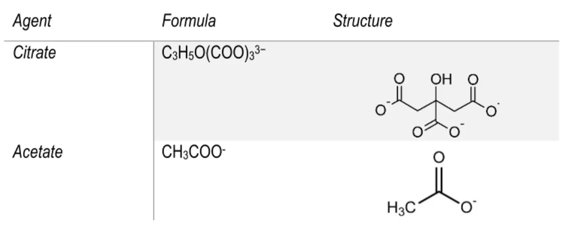
Organic agents are also used to form complexes with the adsorbed metal and recover it from the stationary phase. In anion exchange chromatography, 90% (v/v) acetic acid in 5M nitric acid of stripping agent can achieve separation of Th, LREE, and HREE.106 Stability studies of the acetate-REE complex points out a correlation between the stability constant and the ionic radius107. The addition of acetate ions in the solution increases the adsorption of uranium on aminometylphosphonic resins.88 Citrate ions seem to operate best at pH 5.108 In most cases, the H2Cit- ion is found to be responsible for the separation process obtained during elution of REE on cationic resin.109 It is also known that oxalate complexes are more soluble in sulfuric media then nitric and hydrochloric acidic media.110 Table 11 shows molecular structures of the stripping agents mentioned above.
Table 11 Structures of popular stripping agents
Agent
Formula
Structure
Citrate
C
3H
5O(COO)
33−Acetate
CH
3COO
-2.3.3 Batch Mode
In IX, batch mode is suitable for preliminary experiments. Batch mode also represents resin in pulp (RIP) processes. RIP describes the way of mixing the resin with the solution in a designated container. The mixture is agitated for a certain time to ensure homogeneity and maximum extraction yields. Mostly used for screening, capacity, and kinetic experiments, batch mode is a fast and easy way to gather information of the resin interactions at equilibrium with the solution.