HAL Id: inria-00465456
https://hal.inria.fr/inria-00465456
Submitted on 19 Mar 2010
HAL is a multi-disciplinary open access
archive for the deposit and dissemination of
sci-entific research documents, whether they are
pub-lished or not. The documents may come from
teaching and research institutions in France or
abroad, or from public or private research centers.
L’archive ouverte pluridisciplinaire HAL, est
destinée au dépôt et à la diffusion de documents
scientifiques de niveau recherche, publiés ou non,
émanant des établissements d’enseignement et de
recherche français ou étrangers, des laboratoires
publics ou privés.
Exploration of Intensive Signal Processing Applications
Calin Glitia, Pierre Boulet, Eric Lenormand, Michel Barreteau
To cite this version:
Calin Glitia, Pierre Boulet, Eric Lenormand, Michel Barreteau. Repetitive Model Refactoring for
Design Space Exploration of Intensive Signal Processing Applications. [Research Report] 2009, pp.21.
�inria-00465456�
a p p o r t
d e r e c h e r c h e
ISRN
INRIA/RR--????--FR+ENG
Thème COM
Repetitive Model Refactoring for Design Space
Exploration of Intensive Signal Processing
Applications
Calin Glitia — Pierre Boulet — Eric Lenormand — Michel Barreteau
N° ????
Centre de recherche INRIA Lille – Nord Europe
Applications
Calin Glitia
∗, Pierre Boulet
∗, Eric Lenormand
†, Michel
Barreteau
†Th`eme COM — Syst`emes communicants ´
Equipe-Projet DaRT
Rapport de recherche n° ???? — August 2009 — 21 pages
Abstract: The efficient design of computation intensive multidimensional sig-nal processing application requires to deal with three kinds of constraints: those implied by the data dependencies, the non functional requirements (real-time, power consumption) and the availability of resources of the execution platform. We propose here a strategy to use a refactoring tool dedicated to this kind of applications to help explore the design space. This strategy is illustrated on an industrial radar application modeled using the Modeling and Analysis of Real-time and Embedded systems (MARTE) UML profile. It allows to find good trade-offs in the usage of storage and computation resources and in the parallelism (both task and data parallelism) exploitation.
Key-words: specification language, parallelism, high-level code transforma-tions, optimizatransforma-tions, design space exploration, refactoring strategy
∗Laboratoire d’Informatique Fondamentale de Lille, Universit´e des Sciences et
Technolo-gies de Lille, Cit´e Scientifique, 59655 Villeneuve d’Ascq, France
l’exploration d’architecture d’applications de
traitement de signal intensif
R´esum´e : La conception efficace d’applications pour le traitement intensif de signal demande de prendre en compte trois types de contraintes : celles d´eriv´ees des d´ependances de donn´ees, les exigences non fonctionnelles (temps r´eel, consommation d’´energie) et la disponibilit´e des ressources de la plateforme d’ex´ecution. Nous proposons ici une strat´egie visant `a utiliser un outil de refactoring d´edi´e `a ce type d’applications pour aider dans l’exploration de l’espace de conception. Cette strat´egie est illustr´e sur une application industrielle de traitement radar, mod´elis´ee en utilisant le profile UML Marte con¸cu pour la mod´elisation et l’analyse de syst`emes embarqu´es temps r´eel. Cela nous permet de trouver de bons compromis entre l’utilisation des ressources de stockage et de calcul et dans l’exploitation du parall´elisme (parall´elisme `a la fois de tˆaches et de donn´ees).
Mots-cl´es : langage de sp´ecification, parall´elisme, transformations de code de haut-niveau, optimisations, exploration de l’espace de conception, strat´egie de refactoring
1
Introduction
Computation intensive multidimensional signal processing applications are pre-dominant in several application domains such as image and video processing or detection systems (radar, sonar). By multidimensional, we mean that they manipulate primarily multidimensional data structures such as arrays. The diffi-culty and the variety of these intensive signal processing applications come from the way the elementary functions access their input and output data as parts of multidimensional arrays. The complex access patterns lead to difficulties to schedule these applications efficiently on parallel and distributed execution platforms such as multiprocessor systems-on-chip. Three kinds of scheduling constraints sum up: data dependency constraints, environmental constraints (real-time, power consumption, etc) and hardware platform constraints (avail-able computation, storage and communication resources). A design exploration tool that would guaranty the respect of some of these constraints (data depen-dencies) while allowing to improve on the others (usage of resources) would be very helpful.
The MARTE (Modeling and Analysis of Real-time and Embedded systems) UML profile [14, 16] is the standard for modeling real-time and embedded sys-tems. It is well suited to model intensive signal processing applications thanks to its Repetitive Structure Modeling extension of UML. This extension is designed to provide ways of compact expression of systems having a repetitive structure or topology by the decomposition into repetitions of regularly interconnected components.
We propose here a refactoring tool (included in Gaspard2 [4, 15], an Inte-grated Development Environment dedicated to the visual co-design for embed-ded systems based on MARTE) for the design space exploration of repetitive MARTE models of intensive multidimensional signal processing applications and we experiment it on a typical radar processing application.
After briefly summarizing the principles of the modeling language in Sec-tion 2, the radar applicaSec-tion used in the paper is described in SecSec-tion 3 and modeled in Section 3.2. Accordingly to the rules of transition from the spec-ification model to the execution model presented in Section 4, the refactoring transformations are used to adapt the application to the execution model by the reduction of array sizes and granularity changes in Section 4.2.
2
Multi-dimensional modeling
To model multi-dimensional signal processing applications, the language must support their core characteristics: multi-dimensional data structures, access to these data structures in a regular way, sliding windows, several sampling rates, cyclic data access (for cyclic space or frequency dimensions) and stateful computations. These requirements have been taken into account in the design of the MARTE Repetitive Structure Modeling package.
Models using the MARTE profile represent visual abstractions that, by the extensive use of the Repetitive Structure Modeling package, aim at expressing a maximum of the parallelism of computations, of targeted architectures and the repetitive distribution of computations on parallel execution units. Throughout the paper we will refer to such models as MARTE RSM models/specifications.
The repetitive specification provides ways to access multidimensional arrays via sub-arrays, the support of sliding windows, the possibility to deal with cyclic data accesses, several sampling rates in the same specification and can express stateful computations such as recursive filters through uniform inter-repetition dependences [7]. To make such models statically scheduleable, rules are im-posed on the specification, namely regarding the single assignment and the complete production of array elements. These rules and a complete formalism of the Array-OL (Array Oriented Language) model of computation (MoC), the theoretical basis of the MARTE RSM models, are available in [3]. A compar-ison to similar models of computation dedicated to signal processing, mainly in terms of allowed data structures and expressiveness, like synchronous data-flow languages (SDF [12] and its multidimensional extensions (G)MDSDF [13], WSDF [9]), functional languages (Alpha [8]) or imperative languages (Sisal [1], SaC [17]), is available in [7].
Formally, with MARTE RSM, an application is a set of tasks connected through ports, representing multi-dimensional arrays characterized by their shape and their direction. The tasks are equivalent to mathematical functions reading data on their input ports and writing data on their output ports. The tasks are of three kinds: elementary, compound and repetition. An elementary task is atomic (a black box), it can come from a library for example. A compound is a dependence graph whose nodes are tasks connected via their ports, it allows to express task parallelism. A repetition is a task expressing how a single sub-task is repeated, each instance of the repeated task operates with sub-arrays of the inputs and outputs of the repetition, making the repetitions independent and therefore parallel by construction, it allows to express data parallelism. For a given input or output, all the sub-array instances have the same shape, are com-posed of regularly spaced elements and are regularly placed in the array. The tiler (one tiler per input or output) concept represents the mathematical ex-pression of the elements of the patterns as tiles of the array, and is composed of: a fitting matrix F , whose column vectors represent the regular spacing between the elements of a pattern in the array; o, the origin of the reference pattern (for the reference repetition) and a paving matrix P , whose column vectors repre-sent the regular spacing between the patterns. We can summarize the pattern construction with one formula. For a given repetition index r, 0 ≤ r < srep(the
repetition space is unique for a repetition task and all its inouts and outputs) and a given index i, 0 ≤ i < spattern in the pattern, the corresponding element
in the array has the coordinates
o + (P F ) · r i !
mod sarray, (1)
where sarray is the shape of the array, spattern is the shape of the pattern, srep
is the shape of the repetition space.
The pattern construction allows the construction ranging from simple block tiled patterns to complex uniform accesses where accesses non-parallel with the axes are combined with strides and modulo. Nonetheless, in real intensive signal processing applications, most of the access remain parallel with the axes, by block or with sliding windows:
Parallel with the axes. With such accesses, all the vectors of the paving and the fitting matrixes contain at most one non-zero value, making the
corre-spondence between the repetition’s or pattern’s corresponding dimension and an array dimension.
Access by blocks. Uniform and perfectly tiled block-like patterns are accessed. The fitting and the paving matrix express parallel with the axes construc-tion where the patterns are continuous tiled blocks in the array (each fitting vector contains just one value equal to 11) and the blocks are per-fectly tiled one after another (paving vectors have non-zero values equal to the dimension of the pattern on the corresponding array dimension). Example 1
An array with a shape of (80, 50) can be tiled into (10, 5) blocks of (10, 8) elements using the following tiler: fitting = (0 1
1 0) , paving = (8 00 10)
as illustrated on the figure on the right.
Entire tiled dimensions. It is a special case of block access where pattern dimensions take entire array dimensions.
Sliding windows. It represents a block access where the blocks do not per-fectly tile on some dimensions, with overlapping blocks which cause array elements to be tiled in multiple patterns. On the dimensions of the sliding, paving vectors do not have non-zero values equal to the dimension of the pattern and the value represents the step of the window on this dimension.
Example 2
Leaving unchanged the paving and the fitting matrix of the block access example and by en-larging the pattern to a block of (10, 12), we have a sliding window access on the first dimen-sion of the array, with a step of 8.
3
STAP radar application
This paragraph describes a MTI (Moving Target Indication) application, whose goal is to detect from an aircraft the objects that move on the ground, and especially move slowly among all the other generally still reflecting surfaces under the radar beam (ground clutter). This is done by receiving the echo from the ground of a periodic sequence of radar pulses (bursts). Radar processing permits to estimate both the position of a target through the delay between transmission of a signal (pulse) and reception of its echo, and its speed through the Doppler effect that affects echoes of several identical pulses sent periodically: the speed of the target results in a (small) variation of its distance from the radar, which is only visible as a phase shift on the radar signal (e.g. around
1Pseudo-identity matrix, on each line or column we can find at most one non-zero value of
Figure 1: STAP.
10 GHz). In this basic approach, Doppler processing consists in a bench of filters (e.g. a Fast Fourier Transform) each tuned towards a particular phase shift between successive echoes. This kind of Doppler processing is in some situations sufficient to separate reflecting objects on the basis of their speeds. When the beam is directed toward the ground, the largest part of the echoed energy is supposed to come from the still objects that compose the ground (called clutter), while the moving objects of interest send weak but phase-shifted echoes. However, the radar beam is not perfectly sharp and has a width of a few degrees, which results in giving to some still objects on the ground at the borders of the beam a relative speed with respect to the aircraft (due to the aircraft’s own speed) and creating undesired interferences over the moving targets echoes: this creates an ambiguity between intrinsic speeds and azimuths of targets. Adaptive filtering techniques, where fixed filters are replaced by filters that are computed at run-time from the received signal itself, help to minimize at best the effects of this unwanted clutter signal: in this MTI case, the Space Time Adaptive Processing is used. In this method, a set of filters is computed at every burst, by solving linear systems whose right hand side terms are reference vectors of theoretical phase patterns expected on antenna sub-arrays at several consecutive pulses, each of which corresponding to a particular (velocity, angle) hypothesis of the target relatively to the aircraft. This is shown in Figure 1 where 2D patterns on dimensions antenna and pulse (rec) are considered to compute filters that remove the natural ambiguity between velocity and azimuth.
3.1
Implementation constraints
Those characteristics are mainly:
A large part of the application is data-flow, manipulating multi-dimensional arrays of data.
The processing chain uses different operators, with in particular different needs in terms of precision and dynamic range.
The main STAP application, GlobalSTAP takes as input an multidimensional infinite array of data from the sensors (InputSignalET ) and, using the steer vectors provided by SteerVectCompIET and the Doppler coefficients provided by Gen Coef DopplerET, processes the data and provides the radar detection results as an infinite array, which are consumed by OutputSignalET for display, storage or post-treatment.
Figure 2: STAP: top level.
the processing chain is dynamic, and varies during run-time by frequent variation of algorithm parameters (sizes of arrays, loop bounds, . . . ) while keeping roughly the same processing graph. This is generally called multi-moding in the radar community.
the computational load is high enough to clearly involve parallel comput-ing hardware.
real-time performance is one of the key requirements, both in terms of computation throughput and latency. This may result from some oper-ational requirements and/or embedded architecture constraints such as memory limitations.
3.2
STAP model
The STAP application was modeled in Papyrus UML using the MARTE Profile2.
Starting from the top level, the application is successively depicted using a compound or repetitive decomposition, until the wanted detail level is reached, represented by elementary tasks that can be deployed on library functions. The top level of the specification, illustrated on Figure 2, describes the global func-tionality and the interaction with the environment.
The infinite dimension of the arrays processed by GlobalSTAP represents the abstraction of time and Figure 3 describes the data-flow level of the application, the infinity repetition (time) of a single STAP data treatment.
Just one sample tiler is shown, expressing how the infinite radar signals, repre-sented by an array of shape {8, 128, 111, ∗} is decomposed into an infinity, {∗}, patterns of shape {8, 128, 111}. The paving matrix of {{0, 0, 0, 1}} expresses the correspondence between the infinite repetition and the last dimension of the ar-ray, while the fitting matrix of {{1, 0, 0, 0}, {0, 1, 0, 0}, {0, 0, 1, 0}} expresses the correspondence between the pattern dimensions and the first three dimensions of the array.
Figure 3: STAP: data-flow level.
Figure 4 illustrates the compound decomposition of the repeated task of Figure 3 into successive repetitive filters, with array sizes and repetition spaces shown on the figure. The tilers that express the pattern/tiles construction for each repetition were not made visible.3
Each repetitive filter has a different functionality and different data access patterns:
PulseCompression takes sliding windows with a step of {1} of {16} values on the third dimension of the input array and computes an average value for each of the pattern.
CovMatrixEstim takes {119, 96} blocks of {10, 8}, with a sliding window with a step of {1} on the second dimension of the input array and expands them into blocs of {80, 80} which will be arranged into an array of size {80, 80, 119, 96}.
AverageCovar eliminates the third dimension of the arrays by computing an average of {119} values.
MatInv takes {96} square matrices of {80, 80} and inverses them.
Stap Filter applies the {128} steering vectors of dimension {80} to each line of the inverted matrices, producing an array of size {128, 96, 80}.
Stap Application compares the filtered values with the initial compressed pulses, by blocks of {8, 10} to identify the movements.
3A complete model is available at http://gforge.inria.fr/frs/download.php/5755/
Figure 4: ST AP decomp os iti on.
For the PulseCompression repetition, starting from each element of the input array (identity paving matrix), a pattern of {16} elements on the third dimension is used to compute a single value, {}, values rearranged into a tree dimensional array with a shape of {8, 128, 96}. The difference of size between the input and the output array on the third dimensions (111 − 96 = 15) is caused by the sliding window accesses, for the last 15 elements the access window will exit the array dimensions. CovMatrixEstim repetition has a similar sliding window functionality, this time 2D blocks with a shape of {10, 8} sliding on the second dimension with a step of 1. These blocks are expanded into {119, 96} square blocks of {80, 80}.
Figure 5: First two filters: tiler construction.
Int Doppler applies the {128} Doppler vectors of size {119} to identify the speeds of the moving targets.
Each repetition is characterized by different repetitive and uniform pattern accesses, data consumption or production, expressed by the tiler informations of each connection inside the repetition, accordingly to relation 1. Figure 5 illustrates the tiler construction for two of the STAP filters, PulseCompression and CovMatrixEstim.
At filter level, each repeated task has an elementary functionality which can be deployed on library functions: matrix inversion, average computations, etc.
MARTE RSM models are static and therefore we have chosen to implement a single mode of the multi-moding functionality mentioned in Section 3.1. Mul-tiple modes can be modeled with the use of control structures based on mode automata have been proposed by Labbani et al. [10, 11] or in the upcoming beta3 or 1.0 version of MARTE (no public reference yet available at the time of writing) but they are outside the scope of this study.
4
Towards an execution model
A MARTE RSM specification expresses the maximum of parallelism through the use of the repetitive decomposition. It describes the data dependencies between the elements of the arrays and, as a direct consequence, a strict partial order between the calls of the tasks. A valid specification must be statically
defined and therefore defines a strict partial order. Indeed, any schedule that respects this order will computes the same output values from the same inputs. The construction rules that assure that a specification is valid are described and proved in [3].
The execution model represents the abstraction of the execution and it must abide with the strict partial order defined by the specification. It is a design intention that, by expressing the minimal order of execution, lots of decisions can and have to be taken when mapping a MARTE RSM specification onto an execution platform: how to map the various repetition dimensions to time and space, how to place the arrays in memory, how to schedule parallel tasks on the same processing element, how to schedule the communications between the processing elements? It is a strength of this specification that the space-time mapping decision is separated from the functional specification. This allows to build functional component libraries for reuse and to carry out some architecture exploration with the least restrictions possible.
We have chosen to make the transition from a MARTE RSM specification to an execution model the most straight-forward possible. Indeed the execution model should reflect the specification. This choice has as advantage that the ex-ecution model remains similar to the structure of the specification (parallelism, granularity), at least until the code generation. A representative example is the generation of VHDL code that will be used for FPGA synthesis4 and where the component structure of the specification can be found in the VHDL modules and even on the FPGA layout. It comes down to the constraint that a com-ponent may starts its execution when all its input arrays are available. This constraint introduces a major problem, represented by the so called “synchro-nization barriers” between the components. Such a barrier is created by the data dependencies; a representative illustration of the problem is the presence of any intermediate array that contains an infinite dimension, which would cause the execution to be stalled in that point. As a solution, some repetitions can be transformed to flows, the execution of the repetitions is pipelined and the patterns are read and written as a flow of tokens (each token carrying a pattern).
4.1
High-level data-parallel transformations
The data-parallel code transformations can be used to adapt the application to the execution, allowing to choose the granularity of the flows and a simple expression of the mapping by tagging each repetition by its execution mode: data-parallel or pipeline. A great care has been taken with these transforma-tions to ensure that they do not modify the precise element to element depen-dences [5,18]. A comparative study between these transformations and the loop transformations in the context of program optimizations can be found in [6]. Loop transformations [2] are used intensively for optimizations at compilation time but the complexity of optimization algorithms is one reason why many compilers still use heuristics.
Our high-level transformations are designed as tools at the specification level that can be used for adapting the application to the execution on parallel em-bedded platforms and for design space exploration, leading to some interesting characteristics:
The transformations work as a refactoring tool, their result is translated into model changes at the same level of abstraction.
The application keeps its exact functionality, the same output values are computed for the same inputs.
As optimization targets, the reduction of array sizes and the parallelism management are the priority. A specification expresses the maximum of parallelism and the transformations can be used to change its granularity for a better mapping on a parallel execution platform.
The specification, the refactoring and the transition to an execution model are separate stages. The same specification can be adapted differently to the execution, accordingly to platform and execution constraints.
Regardless of their role, all these transformations have a similar impact on an application, by redistributing repetitions through the hierarchy levels, with the creation or suppression of hierarchy levels.
Taking each transformation one by one, we have:
Fusion takes two successive repetitive tasks, creates a superior hierarchy level for the computed common repetition, while what is left of the initial repetitions is placed on the inferior hierarchy level, minimizing the size of the intermediate array.
Tiling splits a repetition into blocks, by creating a hierarchy level. Change paving (either by dimension creation or by linear growth) acts
on redistributing repetitions through successive levels of hierarchy and modifying the granularity of the application.
Collapse, by being the opposite of fusion and tiling, suppresses the superior hierarchy level, its repetitions being added to each of the inferior level repetitions.
4.2
Refactoring using high-level transformations
Next, we will see how the STAP specification can be adapted to the execution using the refactoring and how a heuristic of transformation chaining can be deduced.
Isolation of the infinite dimensions. The presence of infinite dimensions (of arrays or repetitions) throughout the application is the first thing to take care of when passing to the execution. An infinity value of a repetition will block the execution in that point and an array with an infinite dimension cannot be placed in a limited size memory. As the infinity is used to express the time (or the data flow), a solution is to isolate the infinity values at a high level of the hierarchy and consider this level as the data-flow level at the execution: the arrays will not be allocated entirely in memory (just the patterns) and an sequential execution will be chosen for the repetition. By the use of the fusion
Figure 6: Tiling into blocks of shape {4}.
transformation on successive infinite repetitions, a common repetition can be computed and will represent the data-flow level at execution5.
The STAP application was modeled already having all the infinity values at one hierarchy level, Figure 3, and therefore this step can be skipped. A spec-ification where the infinity values would have been at the filter decomposition level, Figure 4, would express the same exact functionality but would necessitate the isolation of the infinity at a data-flow level before passing to the execution. Granularity change. Execution constrains may impose changes in the gran-ularity of an application. Taken for instance, if we have 4 processors and want to execute the repetition of Figure 3 in parallel, a tiling transformation can be used to split the repetition into blocks of 4 repetitions that will be placed on the 4 processors and executed in parallel, while the sequence of blocks will represent the data-flow level. It is what we call changing the granularity of a repetition and the result of such transformation is shown on Figure 6.
Reduction of the size of the intermediate arrays. The reduction of the size of the intermediate arrays can be achieved by the use of the fusion trans-formation. An elementary fusion computes the minimum intermediate array between two successive repetitions.
Definition 1 (Minimum intermediate array) Between two successive rep-etition tasks6, a minimal intermediate array is represented by a minimum group
of patterns produces by the first task that allows the second task to execute at least once, therefore producing elements and in consequence allowing a non-blocking execution.
5The fusion of two infinite repetitions that fails to isolate the infinity at top level indicates
an invalid specification.
Figure 7: Repetitions of first two tasks after the fusion.
Remark 1 The fusion computes this minimum group of intermediate patterns and transforms the application by creating a common repetition with two sub-repetitions and an intermediate array reduced to the minimum group of patterns. Example 3 Figure 7 shows the result of fusion for the repetitions of Figure 5. A common repetition with a shape of {119, 96} is computed and two sub-repetition of {10, 8} and respectively {} on the second level of hierarchy. The minimum group of patterns produces by the first sub-repetition that allow the execution at least once7 of the second sub-repetition is of {10, 8, 1}, and therefore the
intermediate array is reduced from the shape of {8, 128, 96} (8×128×96 = 98304 memory elements reduced to 10 × 8 × 1 = 80, with a factor of 98304/80 = 1228.8 times).
Definition 2 (Multiple fusion) A fusion between several connected repetitive tasks can be achieved by the chaining of elementary fusion and collapse trans-formations. Following the dependence order between tasks, each task is fusioned with the result of the previous fusion8, while a collapse transformation limits the
explosion of hierarchy levels.
Remark 2 By a multiple fusion, just the last9intermediate array is minimized.
The other intermediate arrays represent the minimum group of patterns needed for the execution at least once of the last repeated task, and not of the repetitive task that consumes this array.
Example 4 Figure 8 shows the fusion of the repetitions PulseCompression ⊕ CovMatrixEstim ⊕ AverageCovar ⊕ MatInv. The first three sub-repetitions
7In this case exactly once, {}. 8We start by fusioning two repetition.
9The order of tasks in a multiple fusion is given by the strict partial order between these
Figure 8: Repetitions of first four tasks after the fusion.
represent minimum execution that allow the last sub-repetition to execute at least once and therefore minimizing the last intermediate array, but not the first two. With such fusion, the first intermediate array is reduces to a size of {10, 8, 1, 119}, 119 times bigger than the minimal reduction reached by the fusion of just the first two repetitions of Figure 7.
Another factor that comes into play is the amount of re-computations intro-duced into the application by the fusion.
Definition 3 (Re-computation) Re-computations are represented by an in-crease of the repetitions for the first task involved in a fusion, caused by the pattern production/consumption between the two tasks.
Remark 3 The complete repetition of a task is given by concatenating all the shapes of the hierarchical repetitions starting at the level of the task and climbing the hierarchy levels to the top level10. Re-computations are represented by an
increase in the complete (takin into account all the levels of hierarchy) repetition of a task after the fusion.
Sliding windows accesses with some initial elements found in several pattern groups determines the first task to compute them several times, after the fusion. In the case of re-computation, the decrease of intermediate array size has as side effect an increase of computations.
Example 5 On Figure 7, the complete repetition of the first repeated task is, by concatenating the repetition spaces of the two hierarchy level, of {119, 96, 10, 8}, while the initial repetition was of {8, 128, 96} and therefore the number of repe-titions increase with a factor of 119 × 96 × 10 × 8/(8 × 128 × 96) = 9.29. Thus, in the case of intermediate values that are used several times, the designer has to make a trade-off between the storage in memory or multiple computations of these intermediate values.
4.3
Reduction of intermediate arrays on STAP
Task Rep. before Rep. after Re-comp.(×) PulseCompression (PC) 8 × 128 × 96 128 × 96 × 8 × 128 × 119 119 × 119 80 × 80 × 119 119 80 × 119 119 1 119 × 128 CovMatrixEstim (CME) 119 × 96 119 × 128 AverageCovar (AC) 80 × 80 × 96 119 × 128 MatInv (MI) 96 119 × 128 StapFilter (SF) 128 × 96 × 80 119 StapApplication (SA) 119 × 128 × 96 1 IntDoppler (ID) 128 × 96 1
The hierarchy of repetitions is represented by brackets in the table. After a complete fusion of the repetitions, a common repetition of {128, 96} is computed and the total repetition for each sub-repetitions is given by multiplication with this common repetition. The re-computation is computed as the division of the repetition after and before the refactoring.
Table 1: Repetitions for the complete fusion.
The first four repetitions are grouped into a common repetition of {96} and the last two into a repetition of {128, 96} of a compound containing two sub-repetitions of the initial tasks, shown on Figure 10.
Figure 9: Top level transformed application.
The reduction of intermediate arrays is the principal use of fusion transfor-mations. Having several successive repetitive tasks, we need a way of reducing at maximum the set of intermediate arrays, while avoiding blocking points in the execution and limiting as much as possible the re-computations introduced by the fusions. Different mappings might impose slightly different heuristics, like forbidding re-computations or the priority of minimizing the array sizes in the detriment of re-computations. On STAP application of Figure 4, we have chosen as objective to minimize the intermediate arrays while limiting the re-computations.
One of the reduction of the intermediate array StapApp→IntDopp to a size of {119} can be observed.
Figure 10: Sub-repetitions of StapApplication and IntDoppler.
Complete fusion. A complete fusion (the fusion of all the repetitions at a hi-erarchy level) is not appropriate in this case, as shown in Table 1 (containing in-formations on the repetitions before, after and the introduced re-computations), where we find ourselves with a great amount of re-computations. Accordingly to Definition 2, the fusion of multiple repetitions minimizes only the last inter-mediate array. Table 2 shows how just two interinter-mediate arrays have a reduced size, as for the others we have even an increase in array size, caused by the multidimensional re-arrangement of patterns as result of the succession of fu-sion/collapse transformations11.
Array Size before Size after Reduction PC→CME 8 × 128 × 96 8 × 128 × 119 0.807 CME→AC 80 × 80 × 119 × 96 80 × 80 × 119 × 119 0.807 AC→MI 80 × 80 × 96 80 × 80 × 119 0.807 MI→SF 80 × 80 × 96 80 × 80 × 119 0.807 SF→SA 80 × 128 × 96 80 × 119 103.26 PC→SA 8 × 128 × 96 8 × 128 × 119 0.807 SA→ID 119 × 128 × 96 119 12288
Array size in memory is given in memory units of the data type of array ele-ments, by the multiplication of the multidimensional dimensions of its shape. In the table, arrays are identified by the tasks that produce/consume the array (Producer→Consumer) and the reduction in size is given by the division of array sizes before and after the refactoring.
Table 2: Array sizes for the complete fusion.
11Initial overlapping accesses are expanded through multiple dimensions with elements
Nonetheless, such a transformation provides useful informations that can be used for finding the best sequence of fusions for our objective. First of all, it provides the fusion order representing the strict partial order between the repetition tasks, in this case: PulseCompression ⊕ CovMatrixEstim ⊕ Aver-ageCovar ⊕ MatInv ⊕ StapFilter ⊕ StapApplication ⊕ IntDoppler. Secondly, on Table 1 we can identify where changes in the re-computations appear and therefore the fusions that introduce re-computations, in our case: MatInv ⊕ StapFilter and StapFilter ⊕ StapApplication. In our goal to reduce at mini-mum the re-computation, it would suggest that the grouping of the first four repetitions and of the last two for fusion, while isolation StapFilter, would not introduce any re-computations.
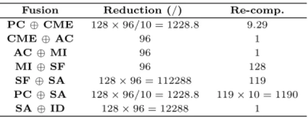
Two-by-two fusions. Other fusions that provide useful informations are the fusions of each two successive repetitions. The results contain informations on the minimal intermediate array achievable between any two repetitions and on the re-computations introduced by the fusions, as shown on Table 3.
Fusion Reduction (/) Re-comp. PC ⊕ CME 128 × 96/10 = 1228.8 9.29 CME ⊕ AC 96 1 AC ⊕ MI 96 1 MI ⊕ SF 96 128 SF ⊕ SA 128 × 96 = 112288 119 PC ⊕ SA 128 × 96/10 = 1228.8 119 × 10 = 1190 SA ⊕ ID 128 × 96 = 12288 1
The maximum reduction of the intermediate array together with the re-computations introduces on the first sub-repetition, achieved by the fusion of each two successive repetitions.
Table 3: Fusion two-by-two.
Best choice fusion. The informations provided by the complete and the two-by-two fusions can guide the choice of a sequence of fusions that achieves the best results for our chosen objective of reducing at maximum the intermediate arrays while limiting the re-computations. The complete fusion suggests the grouping of the first four repetitions and of the last two but the two-by-two fusions indi-cate that the fusion of the first two repetitions introduces re-computations with a factor of nearly 10 for a reduction of array size with a factor of 1228.8. We have two alternatives for the first group of repetitions:
If the re-computation factor of 10 is acceptable, we can group the first four repetitions for the fusion.
Otherwise, just repetitions two to four will be fusioned, with no re-computations. For illustration, we have chosen the first alternative, grouping the first four tasks and the last two. The result shows a reduction to maximum (accordingly to Ta-ble 3) of arrays: CovMatEst→AvCov, AvCov→MatInv and StapApp→IntDopp but a reduction non-maximal for PulCompr→CovMatEst. On the second level of the hierarchy, by the fusion of the two sub-repetitions, PulseCompresion and CovMatrixEstim, we can further reduce (to maximum) this array, with as result
the presence of three levels of repetitions for these two repetitions. The array-size reductions are shown in Table 4, while the repetitions and re-computations in Table 5.
Array Size before Size after Reduction PC→CME 8 × 128 × 96 8 × 10 1228.8 CME→AC 80 × 80 × 119 × 96 80 × 80 × 119 96 AC→MI 80 × 80 × 96 80 × 80 96 MI→SF 80 × 80 × 96 80 × 80 × 96 1 SF→SA 80 × 128 × 96 80 × 128 × 96 1 PC→SA 8 × 128 × 96 8 × 128 × 96 1 SA→ID 119 × 128 × 96 119 12288
Table 4: Array sizes for the best choice fusion.
Task Rep. before Rep. after Re-comp. PC 8 × 128 × 96 96 × 119 × 10 × 8 1 ! 80 × 80 1 9.29 CME 119 × 96 1 AC 80 × 80 × 96 1 MI 96 1 SF 128 × 96 × 80 128 × 96 × 80 1 SA 119 × 128 × 96 128 × 96 × 119 1 ! 1 ID 128 × 96 1
Table 5: Repetitions for the best choice fusion.
A part of the transformed application accordingly to the previous algorithm are illustrated on Figure 9, the transformed filters level, and on Figure 10 the sub-repetitions for the last two tasks.
4.4
Result analysis
In the previous section we have seen how the high-level transformations can be used to adapt a specification to the execution. Optimizations can be of two kinds, platform dependent or general-purpose. The reduction of intermediate arrays can be considered as a general-purpose optimization but, as shown, exe-cution constrains can guide the choice of fusions that lead to the reduction of in-termediate arrays. The granularity changes, through the use of transformations like change paving, tiling or collapse, are more platform-dependent optimiza-tions, aiming at the adaptation of the specification to the execution platform and the optimization of the placement of repetitions on parallel architectures.
Signal processing applications are often represented as successive repetitive filters, as the case of the STAP application of Figure 9. The complex pattern accesses makes it impossible to reduce at maximum every intermediate array and sometimes only with the introduction of additional computations. We have shown how, by exploring some fusion configurations, we can extract informa-tions that lead us to the best choice of chain of transformainforma-tions. The complete fusion provides informations on the strict partial order and on where changes in re-computations appear, while the two-by-two fusions provide the values of the maximum achievable reductions and on the re-computations introduced by such a reduction. These informations were used to separate the repetitions into groups by forbidding fusions that introduce considerable re-computations. Dif-ferent objectives and difDif-ferent applications might determine the alternative use
of fusions, taken for instance the presence of an infinite dimension intermedi-ate array, where the elimination of the infinite dimension has priority on the introduced re-computations.
Acknowledgement
This work has been partially supported by the Ter@ops [19] project of the System@tic competitiveness pole.
5
Conclusions
The present article shows how high-level data-parallel transformations can be used to explore the design space of multi-dimensional intensive signal processing applications with the objective of adapting a specification to the execution. In the context of Gaspard2 environment [4], using a visual UML interface and the MARTE profile, multi-dimensional intensive processing applications can be modeled, together with repetitive architectures and repetitive placement of the applications on such architectures. Before the code generation, a MARTE RSM specification must be adapted to the execution platform by reducing array sizes and adapting the application’s granularity to the architectural and execution constraints. Starting from an application model, different strategies can be chosen to adapt the specification to the execution. These strategies together with different mappings can be easily explored with possible feedback from the code generation, simulation or execution. As future work, these different strategies could be implemented and integrated in the environment together with a semi-automatic refactoring: proposition to the user of different strategies with computed gains in array size reduction and re-computations.
References
[1] I. Attali, D. Caromel, Y. syau Chen, J. luc Gaudiot, and A. L. Wendelborn. A formal semantics for sisal arrays. In Proc. Joint Conf. Infor. Sci., Sept. 1995. [2] D. F. Bacon, S. L. Graham, and O. J. Sharp. Compiler transformations for
high-performance computing. Technical report, University of California at Berkeley, Berkeley, CA, USA, 1993.
[3] P. Boulet. Formal semantics of Array-OL, a domain specific language for inten-sive multidimensional signal processing. Research Report RR-6467, INRIA, Mar. 2008.
[4] DaRT Team. Graphical Array Specification for Parallel and Distributed Com-puting (GASPARD2). http://www.gaspard2.org/, 2009.
[5] P. Dumont. Sp´ecification Multidimensionnelle pour le traitement du signal syst´ematique. Th`ese de doctorat (PhD Thesis), Laboratoire d’informatique fon-damentale de Lille, Universit´e des sciences et technologies de Lille, Dec. 2005. [6] C. Glitia and P. Boulet. High level loop transformations for multidimensional
signal processing embedded applications. In SAMOS 2008 Workshop, Samos, Greece, July 2008.
[7] C. Glitia, P. Dumont, and P. Boulet. Array-OL with delays, a domain specific specification language for multidimensional intensive signal processing. Multidi-mensional Systems and Signal Processing, 2009.
[8] R. M. Karp, R. E. Miller, and S. Winograd. The organization of computations for uniform recurrence equations. J. ACM, 14(3):563–590, July 1967.
[9] J. Keinert, C. Haubelt, and J. Teich. Modeling and analysis of windowed syn-chronous algorithms. In International Conference on Acoustics, Speech and Signal Processing (ICASSP), pages III–892– III–895, 2006.
[10] O. Labbani, J.-L. Dekeyser, P. Boulet, and E. Rutten. Introducing control in the gaspard2 data-parallel metamodel: Synchronous approach. International Work-shop MARTES: Modeling and Analysis of Real-Time and Embedded Systems (in conjunction with 8th International Conference on Model Driven Engineering Lan-guages and Systems, MoDELS/UML 2005), Oct. 2005.
[11] O. Labbani, J.-L. Dekeyser, P. Boulet, and E. Rutten. UML2 profile for modeling controlled data parallel applications. In FDL’06: Forum on Specification and Design Languages, Darmstadt, Germany, Sept. 2006.
[12] E. A. Lee and D. G. Messerschmitt. Static scheduling of synchronous data flow programs for digital signal processing. IEEE Trans. on Computers, 36:24–35, Jan. 1987.
[13] P. K. Murthy and E. A. Lee. Multidimensional synchronous dataflow. IEEE Transactions on Signal Processing, 50(8):2064–2079, Aug. 2002.
[14] Object Management Group. A UML profile for MARTE, 2007. http://www. omgmarte.org.
[15] E. Piel, R. Ben Atitallah, P. Marquet, S. Meftali, S. Niar, A. Etien, J.-L. Dekeyser, and P. Boulet. Gaspard2: from MARTE to SystemC simulation. In Modeling and Analyzis of Real-Time and Embedded Systems with the MARTE UML profile DATE’08 Workshop, Mar. 2008.
[16] L. Rioux, T. Saunier, S. Gerard, A. Radermacher, R. de Simone, T. Gautier, Y. Sorel, J. Forget, J.-L. Dekeyser, A. Cuccuru, C. Dumoulin, and C. Andre. MARTE: A new profile RFP for the modeling and analysis of real-time embedded systems. In UML-SoC’05, DAC 2005 Workshop UML for SoC Design, Anaheim, CA, June 2005.
[17] S.-B. Scholz. Single assignment c: efficient support for high-level array operations in a functional setting. J. Funct. Program., 13(6):1005–1059, 2003.
[18] J. Soula. Principe de Compilation d’un Langage de Traitement de Signal. Th`ese de doctorat (PhD Thesis), Laboratoire d’informatique fondamentale de Lille, Universit´e des sciences et technologies de Lille, Dec. 2001. (In French).
Centre de recherche INRIA Bordeaux – Sud Ouest : Domaine Universitaire - 351, cours de la Libération - 33405 Talence Cedex Centre de recherche INRIA Grenoble – Rhône-Alpes : 655, avenue de l’Europe - 38334 Montbonnot Saint-Ismier
Centre de recherche INRIA Nancy – Grand Est : LORIA, Technopôle de Nancy-Brabois - Campus scientifique 615, rue du Jardin Botanique - BP 101 - 54602 Villers-lès-Nancy Cedex
Centre de recherche INRIA Paris – Rocquencourt : Domaine de Voluceau - Rocquencourt - BP 105 - 78153 Le Chesnay Cedex Centre de recherche INRIA Rennes – Bretagne Atlantique : IRISA, Campus universitaire de Beaulieu - 35042 Rennes Cedex Centre de recherche INRIA Saclay – Île-de-France : Parc Orsay Université - ZAC des Vignes : 4, rue Jacques Monod - 91893 Orsay Cedex
Centre de recherche INRIA Sophia Antipolis – Méditerranée : 2004, route des Lucioles - BP 93 - 06902 Sophia Antipolis Cedex
Éditeur
INRIA - Domaine de Voluceau - Rocquencourt, BP 105 - 78153 Le Chesnay Cedex (France)