HAL Id: hal-01599435
https://hal.archives-ouvertes.fr/hal-01599435
Submitted on 3 Oct 2017HAL is a multi-disciplinary open access archive for the deposit and dissemination of sci-entific research documents, whether they are pub-lished or not. The documents may come from teaching and research institutions in France or abroad, or from public or private research centers.
L’archive ouverte pluridisciplinaire HAL, est destinée au dépôt et à la diffusion de documents scientifiques de niveau recherche, publiés ou non, émanant des établissements d’enseignement et de recherche français ou étrangers, des laboratoires publics ou privés.
Thermal Estimations to Support Buildings Retrofit:
Which Envelope to Manufacture?
Andres Felipe Barco Santa, Élise Vareilles, Michel Aldanondo
To cite this version:
Andres Felipe Barco Santa, Élise Vareilles, Michel Aldanondo. Thermal Estimations to Support Buildings Retrofit: Which Envelope to Manufacture?. IEEM 2015 - IEEE International Conference on Industrial Engineering and Engineering Management, Dec 2015, Singapore, Singapore. pp.691-695. �hal-01599435�
Abstract – In order to reduce energetic consumption, buildings may be retrofitted by covering them with an insulation envelope composed of rectangular parameterizable panels. In such scenario different envelopes configurations are possible to cover the same building. Thus, a crucial aspect of the retrofit is to select, among potential solutions, those ones providing good thermal performance at reasonable cost. In this paper are discussed which characteristics are part of a panels-made envelope, how to compute their performance and associated cost, and a bi-criteria function evaluating the envelope. We compute thermal and cost estimations with respect to the spatial positioning of panels configuring the layout. The aim of our contribution is to assist architects in their decision-making process. Conception and implementation of the thermal retrofit are then supported by our estimations.
Keywords – Thermal estimation, building retrofit, support system, decision-making
I. INTRODUCTION
According with some studies [1,2,3], energy consumption in buildings already overcome consumption in transport and commercial sectors. Some figures have alarmed governments around the world on the possible problems raised by such current energetic consumption and the possibility of its increasing. For instance, building energetic consumption in Europe represents more than 37% of the total energy consumption [1]. Some strategies applied to new buildings construction have already begun to address the problem. But, new buildings construction represent a reduced number of the total buildings in most countries. Thus, new buildings construction has to come along with old buildings thermal retrofit.
A thermal retrofit may be achieved by covering the entire building with a panels-made envelope: Insulating the building in order to reduce the heat transfer between the interior and exterior [4,5]. Automation of the process makes it possible to scale it in industrial proportions and its conception by means of decision support system [6] becomes relevant to create harmony among the different stages of the retrofit. A crucial aspect of the retrofit automation lies on how to differentiate among potential envelopes solutions those ones that provide good thermal performance at a reasonable cost. Selecting the appropriated insulating envelope is a pre-condition to start the manufacturing of parameterizable panels and thus part of the industrialization process management.
Our work follows the same goal of [7], where energetic performance simulations are run of for each floor in a setup for house interior design. We focus on providing energetic performance estimations for a given retrofit envelope. In particular, criteria for estimations are the (energetic) thermal performance achieved by a given panels-made envelope and the cost of bill of material. Customization for envelopes in our estimations respects industrial conditions as they allow difficulties and limitations of the manufacturing process, transportation and environmental conditions to constrain the dimensions of panels creating the insulating envelope.
In this communication we address the following topics. First, we discuss which characteristics are part of a panels-made envelope. Second, we provide some criteria to estimate the performance of a given envelope. Finally, we use a layout generation algorithm to provide and rank different consistent solutions for a given facade. The ultimate goal is to provide performance estimations that allow architects to select, given aesthetics preferences or other subjective criteria, the appropriated panels-made envelopes. Conception and implementation of the retrofit, as well as the decision-making process of architects, are then supported by our results.
The paper is structured as follows. In Section II the retrofit problem is introduced. In Section III we present the thermal properties of the envelope and the criteria on how to compute their thermal performance with respect to the layout plan, their costs in € and a bi-criteria function relating both of them. In Section IV are shown some estimations thrown by our own decision support system, including envelopes comparisons on their performance and cost, for some real residential buildings in France. Finally, some conclusions are discussed in Section V.
II. BUILDING RETROFIT IN A NUTSHELL The CRIBA project (for its acronym in French of Construction and Renovation in Industrialized Wood Steel) aims to industrialize high performance thermal renovation of apartment buildings [5]. This industrialization is based on an external new thermal envelope which wraps the whole building. The envelope is composed of prefabricated rectangular wood-made panels comprising insulation and cladding, and sometimes including in addition, doors, windows and solar modules. Each panel of the envelope is hanged directly onto the facade in order to create the insulation. The retrofit follows a series of steps going from the building site
Thermal Estimations to Support Buildings Retrofit:
Which Envelope to Manufacture?
A. F. Barco, E. Vareilles, M. Aldanondo
Université de Toulouse – Mines d'Albi, Albi, France (corresponding author e-mail: abarcosa@mines-albi.fr)
through the elaboration of panels and ending in its assembly [5]. At each level a set of descriptive queries are made to the user (an architect, for instance). Each answer has a potential impact on the permissible dimensions of panels. For example, the inaccessibility of a given facade may limit the dimensions of panels and therefore the surface covered by each one. Inferior levels of the renovation inherit information from higher levels.
Given that the retrofit problem is, in essence, a tessellation [8], no overlapping of panels nor holes can be present in an insulating envelope. Each panel is associated to a given cost (bill of material), an energetic thermal performance and an on-site assembly order. An assumption is that costs and energetic performance are in proportion with the panels dimensions. Additionally, for an accurate estimation of energetic performance it is necessary to take into account windows, doors, firewalls and other kind of joinery. Also, including solar modules to panels helps to improve energetic performance of buildings. However, solar modules inclusion are not taken into account as we focus first on the thermal estimation given the layout.
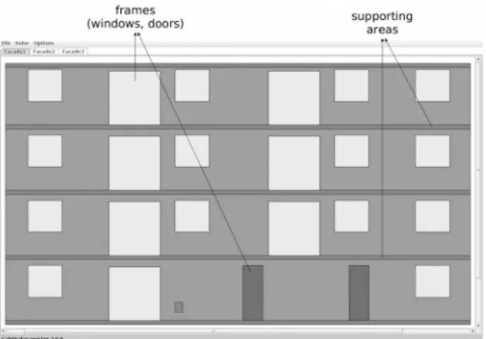
Consider the facade to renovate of Fig. 1. Horizontal and vertical lines, called supporting areas, represent available places to attach panels. They correspond to possible locations for the fasteners supporting the weight of panels. Been able to properly attach panels is important because, as we are dealing with building facades, layout plans must take into account natural forces (e.g. gravity and wind).
Keep in mind that, whereas panels have well-defined geometric shapes, dimensions and relations, their number is not known in advance. This means that different envelope configurations are possible for a given facade, with different number of panels and different panels dimensions. However, they may provide different thermal performance, costs and aesthetics aspects, therefore architects should be able to select, according to their preferences and environmental laws, the envelope to be implemented.
Fig. 1. Original facade in French community.
To create a given envelope made out of panels, we must consider several constraints relating geometrical entities in the facade, structural properties and even transportation issues. In essence, generating a valid layout plan is a combinatorial problem [9,10,11]. In this document, however, we are not interested on how the different elements of the facade relate to the envelope nor how the layouts plans are drawn. Instead, we focus our attention on how to discriminate between good and not so good solutions given their heat transfer between the interior and exterior of the building and their associated cost, and let the aesthetic aspects to the final user. Further information on how to generate these envelopes is found in [12] and information on layout synthesis may be found in [10].
III. THERMAL PERFORMANCE
Intuitively, the insulation provided by a given panel depends on the covered surface. Thus, the heat transfer of a single panel is in proportion with its dimensions. Given that all panels in a retrofit are produced by a single manufacturer, we assume that all panels in a given layout plan has the same internal structure and properties in such a way that any panel is indistinguishable from any other except for its dimensions and position over the facade. The performance of a given layout is computed with respect to the plan and not panels internal structure.
Now, differences on thermal performance for different envelopes for a given facade do not depend on the facade dimensions. Considering that a valid envelope is the one covering all the facade, then it is the case that the summation of all panels areas is equal to the facade area, no matter how many panels or in which position they are. Thus, the thermal performance of a layout plan is based on the length of joints: It is between the junction of two consecutive panels, plus facade perimeter, where the biggest heat leak exists. Hence, an envelope composed by one panel will provide better insulation that an envelope of two panels over the same facade.
In Fig. 2 we can see that the envelope on the left has less panels than the one at the right. Although both layouts are valid because they cover the entire facade, they do not have the same thermal performance and cost. Facade in literal (b) has a bigger thermal transfer because its junctions length is bigger (15 meters * 2 + 10 meters * 6 = 90 meters) than the layout of facade in literal (a) (15 meters * 4 + 10 meters * 2 = 80 meters). Additionally, facade in literal (b) is more expensive because, although they represent the same covered surface, manufacturing more panels is more costly.
As expected, the thermal performance depends largely on the panels materials and different kind of sealing. But, such information is manufacturer dependent and not panel positioning dependent. Also, impact of frames on the performance is not computed because it is independent of the layout plan. Lets study this fact further. First, lets take into account that a given frame in a facade must be
Fig. 2. Two valid envelopes with different.
covered by one and only one panel.
Now suppose that the thermal transfer generated by a frame is FT. It is the case that the thermal transfer of the frame is added to the panel that is covering it, no matter which panel it is. Thus, if there are five frames in the facade, their thermal transfe will be added to the total thermal transfer of the layout plan independently of which panels are covering the frames and regardless of how many panels the layout is composed of. Therefore, the performance, that we call thermal transfer coefficient (ttc) measured in meters, of a layout plan depends only on the length of junctions between two consecutive panels. Computing the length of the junctions for a given envelope is straightforward as shows formula (1)
ttcfac=
∑
i= 1 Nwi+hi (1) where ttcfac stands for thermal transfer coefficient for facade fac, wi and hi represent the width and height of panel i, respectively, and N is the number of panels composing the envelope. Note that thermal performance of a given building also depends in the joinery over the facade. Furthermore, including solar modules on panels will considerable improve energetic performance of the building. Nevertheless, such attributes are facade and user dependent and thus we let them out of the analysis to focus only on the envelope (layout plan).
The cost of a layout plan is computed with respect to the cost of a panel of a given manufacturer. One of the associated companies in the CRIBA project has provided us partial information on how to compute the costs cp for panels they manufacture. Fomula (2) represent the knowledge on how to compute the cost of an envelope
cfac=
∑
i=1 N
(wi×hi)×(α−wi−hi) (2) where wi and hi represent the width and height, respectively, of panel i and α is a factor that depends
on the manufacturing process. As the formula express it, the term (α−wi−hi ) decreases with the panel's size and thus manufacturing large panels is less costly, globally, than manufacturing small ones.
Now, in order to rank envelope layouts it is necessary to evaluate alternatives using a multi-criteria analysis method. The simplest method for this bi-criteria scenario is to use a weighted sum model. The bi-criteria function to evaluate an envelope is presented in formula (3)
eefac=β×norm
(
ttcfac)
+θ× norm(
cfac)
(3) where eefac stands for envelope evaluation of facade fac, and norm is a function to normalize values to the same interval. In our particular case, due to the energetic performance goals, the weight of the thermal transfer coefficient is bigger ( β= 0 .7 ) than the weight associated to the cost (θ= 0. 3 ). Of course, this may be subject to change due to user preference and limitations.IV. EXPERIMENTS
In this section we present some estimations of energetic performance using a constraint-based prototype [13] implemented on Java that uses a greedy approach to generate compliant layout plans as explained in [12]. Each case is part of the site La Pince in the commune Saint Paul-les-Dax in the area of Landes, France.
Configuration for our estimations are as follows. Each panel is configured in a given orientation, either horizontal or vertical. All panels in an envelope have the same width and height lower bound of 0.9 meters. Their upper bounds are given as parameters and depend on the orientation of the panel. Configuration of panel dimensions are necessary due to the limitations on the manufacturing process and due to the constrained nature of layout synthesis problems [11].
Now, given that each facade has many different valid solutions and some valid solutions using the minimum number of panels, we need a way to generate all possible layout plans and take from them the best ones. Therefore, we use a basic search strategy to explore the search space and enumerate all solutions found. Our explored search tree is binary: Left branch positions a horizontal panel in and the right branch places a vertical one.
After all solutions in the search tree have been found, we proceed by enumerate them according with the number of panels. Solutions are sorted with respect to the number of panels in the layout plan because, as we have shown, the less panels the better insulation. Finally, our decision support system shows to the user a subset of all solutions. Simply put, the user inputs a requirement on the acceptable thermal performance and envelope cost, and then the system presents all solutions that perform better or equal than the acceptable values. Ergo no solution is possible. Presenting acceptable layouts is important in our
industrial scenario because maybe a layout is adequated but, according to architects request and aesthetic considerations, a different layout may be implemented.
Lets consider again the facade presented in Fig. 1 that includes windows, doors and supporting areas. Two different layout plans using horizontal panels and another two different layout plans using vertical panels are presented. These solutions may not be the best ones but are useful to see differences among valid layout plans.
Fig. 3 shows an horizontal layout plan which has a thermal transfer coefficient of ttc = 126.67 m, a cost of c = 22756 € and an envelope evaluation of ee = 6915.61.
Fig. 3. First solution horizontal panels.
In Fig. 4 we present the configuration of the same facade in Fig. 1. In this case the computed heat transfer coefficient is ttc = 126.67 m, with a cost of c = 22722.6 € and evaluation of ee = 6905.44.
According to the bi-criteria function, the best layout plan is the one in Fig. 4. Nevertheless, the user may consider that the facade in Fig. 3 is more appropriated from an aesthetic point of view or another subjective criteria. The support system is in charge of providing the estimations but at the end is the user who makes the final decision on the implemented solution.
Fig. 4. Second solution horizontal panels
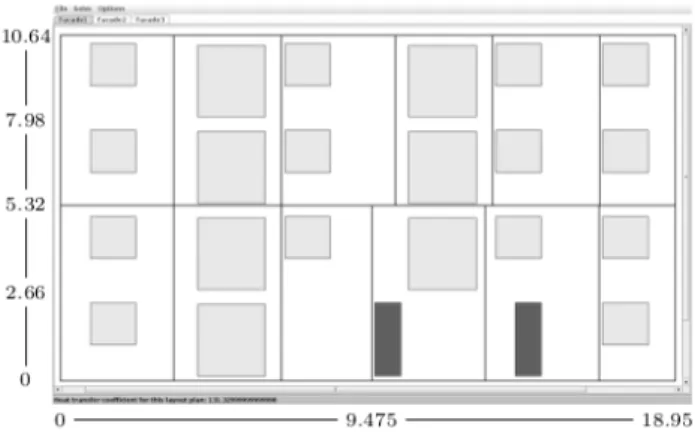
Conversely, in Fig. 5 we present the configuration of the same facade of Fig. 1 using vertical orientation which computes a heat transfer coefficient of ttc = 131.32 m, cost of c = 23482.2 € and evaluation of ee = 7136.58.
Fig. 5. First solution vertical panels.
Fig. 6 shows another vertically oriented layout plan with a heat thermal coefficient of ttc = 131.33 m, cost of c = 23197.48 € and envelope evaluation of ee = 7051.17. Again, the second layout behaves better according to our evaluation criteria but it lacks of the symmetrical properties of the first one.
Fig. 6. Second solution vertical panels.
In the case of the facade in Fig. 1 our prototype decision support system finds 129 different valid layout plans. However, our prototype may present all solutions that perform equal or better than a given value inputed by the user. As the expert in our application domain, an architect, has already an idea of a valid layout plan, he adds his knowledge to reduce the valid solutions. Thus, using our example, the architect may ask envelopes layouts with thermal transfer coefficient less or equal than 127 m and cost less or equal than 23000 € as acceptable solutions. Consequently, the decision support system shows only the solutions, in this case 12 layout plans, that perform better or equal than the inputed requirement.
V. CONCLUSIONS
Controlling energy consumption in buildings is one of the major challenges of the 21th century. Reducing energy consumption in buildings is now focused on the retrofit of
existing buildings. To achieve retrofit goals set by different governments around the world, it is essential to assist massive retrofit with technological tools and industrial methods rather than artisanal ones. In particular is necessary systems that support the industrialization on its different stages.
This work is part of a French project called CRIBA: A joint effort between academics at Ecole des Mines d'Albi -Carmaux and several French companies. Essentially, it investigates the possibility of automated building renovation based on prefabricated rectangular panels and supported by a decision support system.
In this communication, we have presented some estimations of thermal performance for different panels-made envelopes. In a first step, we have briefly describe the retrofit problem with respect to the insulation of the building. Then, we have introduced the thermal performance computation for a given layout plan along with its associated cost. Additionally, in order to evaluate envelopes, we have linked their thermal performance and costs by means of a bi-criteria function. Finally, we have shown some experimental cases on a real French facade and presented their evaluation results. Our goal with the estimations is to help architects to design the retrofit of buildings in a way that satisfies not only environmental laws but also all constraints regarding the manufacturing process. We have shown that using thermal performance estimations by means of support systems is an appropriated way to assist architects decision-making.
Future work. Specifications for our estimations include
the possibility of constraining panels dimensions as is the case in the industrial scenarios where transportation, manufacturing and other limitations are present. However, we consider two strategic directions to improve our analysis and prototype support system.
1. On the one hand, it is necessary to enhance the search tree with better exploration capabilities. For instance, using a Branch and Bound strategy [14] we can avoid exploring nodes that, given their partial layout and evaluation, do not satisfy the user criteria. Thus, at the end of the process will only remain those layout plans that the user can actually use.
2. On the other hand, further knowledge must be added to the support system in order to include thermal leaks of windows and other kind of joinery over the facade. In particular, the building retrofit scenario includes the possibility to attach solar modules over the panels creating the envelope which is, in fact, trend implemented in design tools used by architects [15]. Thus, computation of energetic performance for the retrofit must strongly consider not only climatological aspects on the analysis but also the impact of such energetic devices on the thermal performance.
ACKNOWLEDGMENT
Authors wish to acknowledge the TBC Généerateur d'Innovation company, the Millet and SyBois companies and all partners in the CRIBA project, for their contributions for extracting the knowledge on panels thermal performance and costs.
REFERENCES
[1] Pérez-Lombard, L., Ortiz, J., and Pout, C. (2008). A review on buildings energy consumption information. Energy and Buildings, 40(3), 394 – 398
[2] Council, U.G.B. (2013). New Construction Reference Guide.
[3] Center, T.E.C. (2011). Energy Conservation Handbook. The Energy Conservation Center, Japan.
[4] M. and Fontanili, F. (2010). Process modelling of industrialized thermal renovation of apartment buildings. eWork and eBusiness in Architecture, Engineering and Construction, 363–368.
[5] E. Vareilles, A.F. Barco Santa, M. Falcon, M. Aldanondo, and P. Gaborit. Configuration of high performance apartment buildings renovation: A constraint based approach. In Industrial Engineering and Engineering Management (IEEM), 2013 IEEE International Conference on, pages 684–688, Dec 2013.
[6] Juan, Y.K., Gao, P., and Wang, J. (2010). A hybrid decision support system for sustainable office building renovation and energy performance improvement. Energy and Buildings, 42(3), 290 – 297.
[7] Rodrigues, E., Gaspar, A.R., and lvaro Gomes (2014). Automated approach for design generation and thermal assessment of alternative floor plans. Energy and Buildings, 81(0), 170 – 181.
[8] Okabe, A., Boots, B., and Sugihara, K. (1992). Spatial Tessellations: Concepts and Applications of Voronoi Diagrams. John Wiley & Sons, Inc., New York, NY, USA. [9] Charman, P. (1993). Solving space planning problems
using constraint technology.
[10] Liggett, R.S. (2000). Automated facilities layout: past, present and future. Automation in Construction, 9(2), pp. 197 – 215.
[11] Zawidzki, M., Tateyama, K., and Nishikawa, I. (2011). The constraints satisfaction problem approach in the design of an architectural functional layout. Engineering Optimization, 43(9), pp. 943–966.
[12] A. F. Barco, E. Vareilles, M. Aldanondo, P. Gaborit, A recursive algorithm for building renovation in smart cities, in: T. Andreasen, H. Christiansen, J.-C. Cubero, Z. Ra (Eds.), Foundations of Intelligent Systems, Vol. 8502 of Lecture Notes in Computer Science, Springer International Publishing, 2014, pp. 144–153.
[13] A. F. Barco, E. Vareilles, M. Aldanondo, and P. Gaborit. Calpinator: A configuration tool for building facades. In 16th International Configuration Workshop, pages 47–54. CEUR Workshop Proceedings, 2014.
[14] Clausen, J. (1997). Branch and Bound Algorithms Principles and Examples. Dept. Comput. Sci., Univ. Copenhagen.
[15] Kanters, J., Horvat, M., and Dubois, M.C. (2014). Tools and methods used by architects for solar design. Energy and Buildings, 68, Part C(0), 721 – 731.