Science Arts & Métiers (SAM)
is an open access repository that collects the work of Arts et Métiers Institute of
Technology researchers and makes it freely available over the web where possible.
This is an author-deposited version published in: https://sam.ensam.eu Handle ID: .http://hdl.handle.net/10985/6827
To cite this version :
Matthieu SCHNEIDER, Laurent BERTHE, Rémy FABBRO, Maryse MULLER, Mariette NIVARD -Gas investigation for laser drilling - Journal of Laser Applications - Vol. 19, n°3, p.5 - 2007
Any correspondence concerning this service should be sent to the repository Administrator : [email protected]
Gas investigation for laser drilling
Matthieu Schneidera), Laurent Berthe, Rémy Fabbro, Maryse Muller, and Mariette Nivard Laboratoire pour PIMM (UMR 8006),
Arts et Métiers Paristech
151 Boulevard de L'Hôpital 75013 Paris, France
This article deals with the gas effect on percussion laser drilling in ms pulse duration range. On the one hand, the flow of assistance gas jet is investigated with and without a target using a strioscopy setup and Pitot’s tube. By this way, the position of shock waves in the supersonic jet and near the target surface is revealed. From this characterization, the distance between exit nozzle and target can be optimized to induce higher pressure on surface and protect optics from liquid ejection. On the other hand, metal liquid and vapor jets from irradiated target are observed with a high-speed camera 共100 000 Img/sec兲. Without assistance gas, a surprising result on the video is a shock wave inside the metal vapor jet like a supersonic flow. The assistance gas limits the propagation of the vapor and facilitates the deposition of metallic liquid around the front surface holes.
Key words: laser drilling, assistant gas, metallic vapor, chock wave
I. INTRODUCTION
Laser drilling in percussion regime is used extensively in aeronautical industries.1 This process consists in irradiating metallic targets with a laser tuned in the MW cm−2 range
共pulse duration in s–ms range兲. The laser energy is ab-sorbed by the surface for the heating, the melting, and the vaporization of the target. This vapor spreads out and pushes the melt pool.2,3 In this case, the drilling is dominated by melt ejection induced by the pressure gradient between the irradiated area and the hole surrounding.
Today, it is impossible to solve analytically equations which describe this process without introducing some ap-proximations then compromising the accuracy of the final solution. This is why parametric and qualitative studies are essential to achieve the miscorrelation between each compo-nent and their own modifications. This allows one to bring out the main parameters, which induce changes in the hole geometry and then capability.
In a previous paper,4 the influence on hole geometry of the gas nature and its pressure in nozzle tank have been explored. In the present one, the flow of the assist gas and the modifications induced by a target located in the flow is investigated. With the help of a strioscopy setup, the position of the shock waves in the supersonic jet and near target sur-face is clearly observed. Nature of the metal vapor jet from irradiated target and the influence of these different flows on the drilling process is discussed using high-speed camera 共100 000 Img/sec兲 images.
The second part describes experimental setups including HL201P Trumpf laser, jet gas characterization diagnostics 共strioscopy and total pressure measurement by Pitot’s tube
technique兲, and laser drilling process observation with high-speed camera. The third part presents results and discussions on the influence of the gas on laser drilling process. II. EXPERIMENTAL SETUPS
A. Lasers
A previous article4 showed that the HL201P laser from Trumpf company presents very useful guarantees for a parametric study: A circular “top-hat” intensity distribution in the focal plane, a pulse reproducibility, and a constant focal plane position for any laser parameters. Laser parameters are given in Table I. With a beam analyzer, all
FIG. 1. Intensity distribution at a constant focal plane in function of peak power and pulse duration.
these laser properties have been measured. Figure 1 presents the intensity distribution at the focal plane. It is close to a circular top hat for all pulse durations and peak powers tested, especially in the focal plane.
The position of the focal plane is also constant for any peak power and pulse duration. The differences between color codes come from different optical densities which have been used in front of the beam analyser to protect it. The spot diameter is constant too and is equal to 共330±10兲m for all parameters. So, the HL201P allows a circular top-hat intensity distribution, a constant focal plane in accordance with the laser parameters. The HL201P is so stable that the difference between holes is not related to laser beam fluctuations.
B. Setup for gas jet characterization
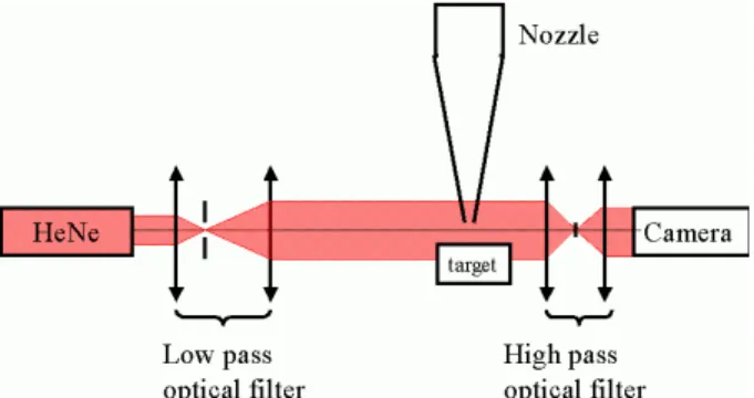
A previous paper4 has shown that gas is probably the source of many fluctuations of the drilling process. To understand how it works, the observation of gas jet has been performed with strioscopy set up showed on Fig. 2 in a schematic representation.
The principle is well known. The area between the target and the exit of the nozzle is illuminated by a plane monochromatic wave that comes from low pass optical filter. The very little difference of density in the gas flow deviates incident light. The high pass optical filter behind, stops the nondeviated beam and the refracted beam realizes an image on camera. Only the area with different densities will appear on the image; typically the shock wave in compressive flow. Figure 3 presents typical images from strioscopy experience for different nozzle pressures共Pnoz兲. The line at the top edge
corresponds to the exit nozzle. From 2 to 5.6 bars, luminous structure corresponds to stationary shock wave profile in the jet.
Total pressure measurements have been done using a Pitot’s tube共Fig. 4兲. It is a representative laser drilled hole connected to a manometer, which allows the measurement. So, the pressure measured is the spatial average of the scalar
pressure field acting by the gas during the drilling process. From these measurements, pressure profiles are determined like in Fig. 6 as a function of working distance 共distance between exit nozzle and target surface⫽WD兲.
C. High speed camera observation
The observation of the laser drilling has been performed with a high speed camera. This camera共Phantom 7, Photon Line兲, can record a video with a resolution of 128⫻64 pixels at 100 000 frames per second. For these drilling records no additional lighting is necessary because the drilling process is very shining. Figure 7 presents typical images produced by the high speed camera. Laser comes from the top of picture and the target is located at its bottom. Drilling has been done on Stanley steel.
III. RESULTS AND DISCUSSIONS A. Strioscopy of the free gas jet
It is well known that the flow becomes supersonic when5,6 Pnoz Pamb=
冉
2 1 +␥冊
关␥/共␥−1兲兴 , 共1兲where Pnoz is the pressure inside the nozzle tank, Pamb is
the pressure surround the experimental setup 共generally the atmospheric pressure兲; ␥ is the ratio between the heat capacities.
According to the gas nature, the flow becomes supersonic for different ratio between nozzle pressure and ambient pressure. Table II contains ratios 共Pnoz/ Pamb兲 for
mono and diatomic which is 2.05 and 1.89, respectively. Figure 3 presents some strioscopic images as a function of Pnoz 共from 0 to 5.6 bars兲 for a diatomic gas. As theory
predicts, above Pnoz= 2 bars, the flow becomes supersonic
and a shock wave is formed inside the jet. The higher Pnoz
is, the longer the distance between the first shock wave and the nozzle exit also.
TABLE I. Measured HL201P laser parameters.
Incident intensity 1 to 22 MW cm−2 Average power 201 W Pulse duration 0.08 to 1 ms Frequency ⬍1 kHz Energy dispersion ⬍1% Temporal dispersion ⬍3%
Diameter in focal plane 330m
FIG. 2. Schematic representation of strioscopy setup.
Besides, these images show that for Pnoz above 2 bars,
the Mach shock disk 共MSD兲 is missing with this nozzle, only the Prandtl reflections appear.6,7They are generated by some imperfections of the lining nozzle. MSD lack shows that the nozzle is correctly shaped at these pressures. The distance between the Prandtl reflections is constant. So, inside a supersonic free jet some stationary shock waves in the flow are observed.
B. Strioscopy of the gas jet with target
The gas parameter, which influences the drilling process, is the total pressure on target surface. As Fieret et al. showed7,8that the surface pressure depends on the distance between the exit nozzle and the target surface. Striosopy images can evidence so.
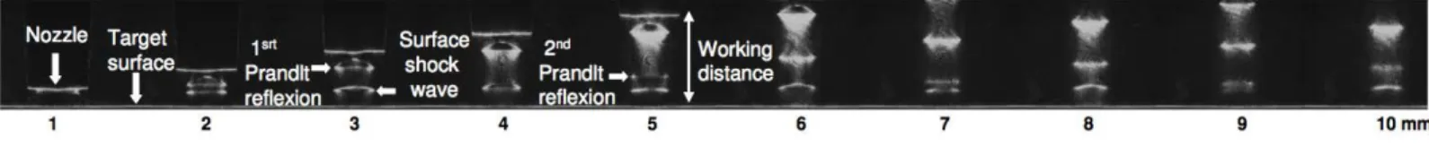
Figure 5 shows pictures performed with strioscopy of the jet with a target surface for WD from 1 to 10 mm. The target is located at the bottom of the images and the nozzle is moved upwards millimeter by millimeter. For this record the Pnoz is 2 bars. For any working distance, shock wave is
visible near the target surface. Above this shock wave, the jet is still supersonic and below it is subsonic. In comparing Fig. 3 for 2 bars 共third picture兲 and Fig. 5 for WD=6 mm 共sixth picture兲 a surface shock wave is generated due to the presence of the target in the jet. Prandtl reflections position is not modified in the jet for constant working distance.
During the moving of the nozzle on Fig. 5, Prandtl’s reflections appear one by one and come out from the surface shock wave. For WD 2, 5, 7, and 9 mm correspond to the emergence of a stationary shock wave from the surface shock wave. For these distances the pressure exerted on the target surface could not be constant.
C. Pressure on target surface
Figure 6 presents the total pressure on target surface 共and so, on the front of hole during drilling兲 as function of WD. As shown by Fieret,7,8 curves correspond to typical profiles of a jet without MSD. Pressure decreases for WD
coming from 0 to 3.5 mm. Above this distance, pressure oscillate with a maximum every 3 mm due to the emergence of the Prandtl reflections shock waves. Their amplitude 共maximum minus minimum兲 decreases with increasing of WD 共1.2 and 0.5 bars for the first oscillation at 5 mm and last one at 18 mm, respectively兲. The mean pressure is close to 2.5 bars. These profiles are independent of the gas nature 共argon and oxygen兲. On Fig. 6, the pressure can be reduced about only one third 共compared to the pressure for WD=0: 4 bars兲 for the working distance below 10 mm. The precision on the positioning, to get a determined pressure on the target surface, is not less than one millimeter corresponding to the distance between a maximum and a minimum.
During the process, ejected liquid can modify the exit nozzle and so pressure profile on target which is very sensitive to nozzle shape.7,8Consequently, a good protection of exit nozzle from degradation or/and a regular nozzle characterization are primordial. For example, for the present experiment, to protect optics and nozzle and to ensure a constant pressure on target, a working distance higher than 10 mm could be quite a good compromise.
D. Drilling without gas
1. Description of the vapor
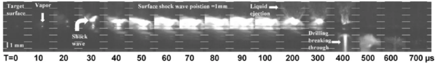
Figure 7 shows a video sequence with the high speed camera. On the first line, images are presented every 10s. The time origin is the first image for which luminosity occurs. So, at this moment, the irradiated area target is vaporized and the vapor pressure is above atmospheric pressure.2Until 20s the vapor expands in the atmosphere and the gas velocity is in the range of 50 m s−1.
At 30s共image 4兲 we see the beginning of a structure construction in the flow and the velocity is now in the range of 100 m s−1. At 40s the structure clearly appears: A MSD is generated clearly in the metal vapor. Moreover, the jet becomes very directional.
As seen previously in Sec. III A, the vapor behaves like the assist gas and the drilled hole play the role of a nozzle. When the ratio between pressure in the hole and pressure around becomes higher than 2.05 bars the flow becomes supersonic; with the hypothesis that the vapor is a
TABLE II. Supersonic ratio共Pnoz/ Pamb兲 condition for mono- and diatomic
gas.
Monoatomic gas Diatomic gas
Supersonic condition 共bar兲
2.05 1.89
FIG. 4. Scheme of a Pitot’s tube.
monoatomic gas. At this moment, the jet becomes directional and a shock wave structure appears inside it. After 100s the whole structure starts to embed into the target and reduces its width size.
2. Description of the melt ejection
At 40s on Fig. 7, the liquid ejection begins. Its starts almost horizontally. Indeed, the process is not stationary, and the bottom of the hole is still closed to the surface. Liquid jet becomes vertical between 300 and 400m when the hole is deeper. In fact, the wall of the hole directs the melt ejection quite vertically. After 400s when the drilling becomes deep the flow of melt ejection is discontinuous but still very vertical.
E. Drilling with an assist gas
With an assist gas, two supersonics jets are opposed to each other.
Figure 8 shows images from a sequence record with the same camera and experimental conditions except the assist gas pressure which is 3 bars on target surface.
1. Description of the vapor
The presence of an assist gas stops the vapor expansion above the surface shock wave.
Only up to 30s共image 4兲, a MSD is generated is the metal vapor. Up to 40s, the vapor shock wave grows in strength but the pressure is not high enough to cross the shock wave induced by the assist gas. The vapor is trapped between the assist gas shock wave and the target surface. It escapes only by the sides and so is not as directional as without gas. Moreover, the hot vapor in this configuration can fall to the target surface and so melt it. At 400s, the vapor is ejected only through the rear of the target by the surface pressure after the opening of the hole.
2. Description of the melt ejection
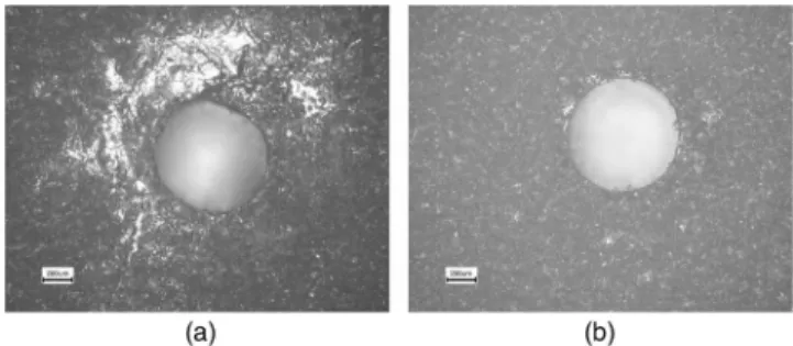
Unlike the vapor, the assist gas does not stop the melt. It just slows it down to the target surface. Figure 9 shows two holes performed with共a兲 and without assist gas 共b兲. The hole on Fig. 9共a兲 is produced with 3 bars surface pressure, and the hole on Fig. 9共b兲 with no gas. Clearly, lot of metal deposition on surface is evidenced around the hole drilled with assistance gas but not for other one without gas.
Concerning the breaking through occurring at 400s 共Fig. 8兲, the pressure inside the hole ejects the melt pool through the front and rear hole. However, the gas on the surface penetrates inside the hole and pushes the melt pool through the rear target. Consequently, there is no more melt ejection by front hole at that time as seen on pictures up to 500s. This observation confirms the ejection of liquid through the rear hole. In the case of applications, this melted metal could pollute a clearly opposite part.
IV. SUMMARY
This paper presents gas investigation in laser drilling based on assistance gas characterization and high speed cam-era observations. Working distance can be optimized to apply high pressure on surface target and to protect optics from liquid ejection during the drilling.
FIG. 6. Pressure on target as function of working distance between the exit
nozzle and the target surface共called WD兲 for a 3.5 bars nozzle pressure for
argon and oxygen gas.
FIG. 7. Video acquisition of laser drilling without gas at 105frames per second共peak power: 16 Kw, pulse duration: 1 ms兲.
FIG. 8. Video acquisition of a breaking through hole with assist gas共pressure on the surface: 3 bars兲 at 105frames per second. Peak power: 16 kW; pulse
duration: 1 ms.
Working distance (mm)
Finally, there are two reasons to use gas for drilling. First, for the optics protection from metallic melt ejections and, secondly, to improve drilling quality when drilling break through occurs.4
However, the gas has some drawback effects: A trapping of the metal vapor, which is locked up below the surface shock wave; a slowdown of the ejected scories; a modifica-tion of the target surface around the front hole.
From these results, the usual gas parameters for percus-sion laser drilling in application could be reconsidered to higher working distance and lower pressure applied.
ACKNOWLEDGMENTS
The authors thank Trumpf Compagny for HL201P laser facilities, Photonlines for high speed camera facilities, and CEA共Commissariat à l‘Energie Atomic兲 and CNRS 共Centre National pour la Recherche Scientifique兲 for financial sup-port.
1C. A. McNally, J. Folkes, and I. R. Pashby, “Laser drilling of cooling
holes in aeroengines: state of the art and future challenges,” Mater. Sci.
Technol. 20, 805–813共2004兲.
2S. I. Anisimov and V. A. Khokhlov, Instabilities in Laser-Matter
Inter-action共CRC Press, Boca Raton, 1995兲.
3V. V. Semak and A. Matsunawa, “The role of recoil pressure in energie
balance during laser materials processing,” J. Phys. D 30, 2541–2552 共1997兲.
4M. Schneider, R. Fabbro, L. Berthe, L. Landais, M. Nivard, and P.
Lau-rens, Parametric study of drilling with new innovative laser source: ap-plication to percussion regime, Proc. Intnl. Congrs. on Appl. on
Applica-tion of Lasers and Electro-Optics共ICALEO’04兲, San Francisco, 2004, pp.
540–546.
5L. D. Landau and E. M. Lifshitz, Mécanique des fluides 2EMEED T6.
共1989兲.
6E. A. Brun, A. Martineau Lagarde, and J. Mathieu, Mécanique des fluides
2EMEEd.共1968兲.
7J. Fieret, M. J. Terry, and B. A. Ward, “Aerodynamic interaction during
laser cutting,” SPIE laser processing: Fundamentals, Applications, and
Systems Engineering, Vol. 668共1986兲, pp. 53–62.
8J. Fieret and B. A. Ward, “Circular and non-circular nozzle exits for
supersonic gas jet assist in CO2 laser cutting,” Proc. 3rd Intl. Conf. on
Laser in Mfg共LIM3兲, Paris, 1986, pp. 45–54.
FIG. 9. Two front holes:共a兲 Drilled with assistance gas 共pressure on the
surface: 3 bars兲 and 共b兲 without gas. Peak power is 16 kW and pulse