HAL Id: hal-02264333
https://hal.archives-ouvertes.fr/hal-02264333
Submitted on 6 Aug 2019HAL is a multi-disciplinary open access archive for the deposit and dissemination of sci-entific research documents, whether they are pub-lished or not. The documents may come from teaching and research institutions in France or abroad, or from public or private research centers.
L’archive ouverte pluridisciplinaire HAL, est destinée au dépôt et à la diffusion de documents scientifiques de niveau recherche, publiés ou non, émanant des établissements d’enseignement et de recherche français ou étrangers, des laboratoires publics ou privés.
Defects and disorder in metal organic frameworks
Anthony Cheetham, Thomas Bennett, François-Xavier Coudert, Andrew
Goodwin
To cite this version:
Anthony Cheetham, Thomas Bennett, François-Xavier Coudert, Andrew Goodwin. Defects and dis-order in metal organic frameworks. Dalton Transactions, Royal Society of Chemistry, 2016, 45 (10), pp.4113-4126. �10.1039/C5DT04392A�. �hal-02264333�
1
Defects and Disorder in Metal Organic Frameworks
Anthony K. Cheetham*1, Thomas D. Bennett1, François-Xavier Coudert2 and Andrew L. Goodwin*3
1 Department of Materials Science and Metallurgy, 27 Charles Babbage Road, University of Cambridge,
CB3 0FS, UK
2 PSL Research University, Chimie ParisTech − CNRS, Institut de Recherche de Chimie Paris, 75005 Paris,
France
3 Department of Chemistry, University of Oxford, Inorganic Chemistry Laboratory, South Parks Road,
Oxford, OX1 3QR, UK
1. Introduction
It is widely recognized in physics and chemistry that the presence of both point and extended scale defects in materials can have a dramatic impact on their properties. In the case of inorganic structures, for example, simple lattice and interstitial vacancies control diffusion and ionic conductivity, while substitutional defects (i.e. impurities and dopants) in semiconductors have a strong influence on electronic conductivity. Dopants can also determine the transport properties of organic materials such as conducting polymers. Point defects in porous materials such as zeolites and carbons affect the chemical nature of the internal pore surface, thus altering in large ways the host–guest interactions (i.e. hydrophobic or hydrophilic nature) and promoting
catalysis. On larger length scales, defects such as stacking faults and dislocations have an important bearing on a material’s mechanical properties and catalytic activity, and can be tuned to optimize performance. Given the relative youth of the field of metal-organic frameworks (MOFs), it is not surprising that relatively little is known about the identity or propensity of their defects, though a very recent review by Fang et al.1 gives a good coverage of the literature from a crystal engineering perspective, with a particular emphasis on porous MOFs and their
applications. The purpose of this short review is to explore the interplay between defects and disorder in both porous and dense MOFs.
We shall focus primarily on defects that are introduced artificially, since these have been quite widely studied. We know, for example, that defects can be used to introduce new functionality into MOFs, e.g. photoluminescence, active sites for catalysis, and enhanced selective adsorption, as well as for fine-tuning properties such as magnetic and ferroelectric phase transitions. It is however also known that the presence of defects may undermine the performance of MOFs, as in the case of porous solids where selective adsorption capacity can be reduced by poor
crystallinity.
It is important to recognize that defects are normally associated with disorder, and so entropic factors are a major driving force in determining the levels of defects in solids. All materials under ambient conditions - however pure they may be - contain intrinsic defects according to the partition function:
𝑛𝑑~ 𝑒−𝑒𝑑
𝑅𝑇
⁄ (1)
where nd is the number of defects of a particular type and ed is the energy required to form them.
The concepts set out for simple ionic solids by Schottky and Wagner in 19302 pointed to the importance of Schottky (equal numbers of complementary cation and anion vacancies) and Frenkel (equal numbers of cation or anion vacancies and interstitials) defects in stoichiometric inorganic solids. These are known as intrinsic defects. Each particular solid normally has a preferred intrinsic, point defect incorporation mechanism; in the case of sodium chloride, for example, the dominant defect is of the Schottky type, and we can estimate that a mole of NaCl contains approximately 104 cation and anion vacancies at room temperature (and as many as 1017
2
at 1000 K). A solid will also contain extrinsic defects due to impurities, and the relative proportions of intrinsic and extrinsic defects will depend on the purity of the sample as well as the temperature. By contrast, we do not know the nature of the intrinsic defects in MOFs. The scope of this mini-review will span both porous and dense MOFs, recognizing that the ease of defect formation may be different. We shall also consider the correlation of such defects, along with the relationship between defects and disorder (section 4), and in particular the extreme case of disorder that is amorphization (section 5). Defects and disorder caused by extra-framework guests or solvent molecules, which are ubiquitous in porous MOFs, and extended defects such as dislocations and stacking faults, which are covered in reference 1, are avoided. The following two sections will give examples of defects on the cation and anion sub-lattices, respectively.
2. Cation defects in metal-organic frameworks
2.1 Examples with metal cation substitution
There are two contrasting synthetic approaches to the formation of substitutional cation defects in MOFs. One approach aims to crystallize the materials from starting solutions containing the two cations in the desired proportions. An appropriate example is taken from calcium and strontium tartrates (C4H4O62-), where crystallization from a solution containing the two cations,
in the presence of the appropriate tartrate ligand, is possible.
(1-x)Ca2+(aq) + xSr2+(aq) + C4H4O62- (aq) Ca1-xSrx(C4H4O6) Scheme (1)
Alkaline earth tartrates can be made in this manner and provide one of the simplest cases of cation substitution in dense MOFs.3 Calcium and strontium L-tartrates are isomorphous and form a complete solid solution, Ca1-xSrx(L- C4H4O6), which obeys Végard’s Law, i.e. the cell volume
is a linear function of composition (Fig. 1).
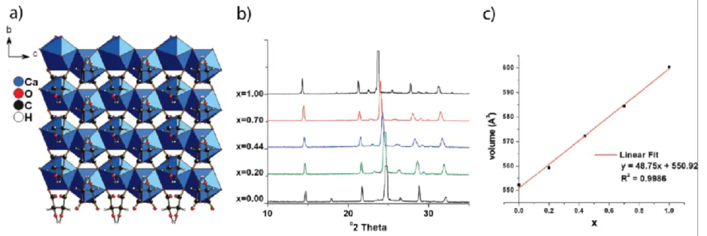
Figure 1. (a) The X-ray patterns of Ca1-xSrx(L- C4H4O6) show systematic shifts as a function of composition. (b) the
unit cell volume obeys Végard’s Law. (c) the structure of Ca(L- C4H4O6) viewed along the a axis. Ca – blue, O –
red, C – black, H – white. Adapted with permission from L. Appelhans et al., J. Amer. Chem. Soc.131, 15375 (2009). Copyright 2009 American Chemical Society.
Complexities arise where, as in the corresponding strontium-barium system, two end-member structures are different. In the case of the meso-tartrate phases, there is a solid solution over a very limited range of composition, Sr1-xBax(meso- C4H4O6) for 0<x<0.1, followed by a two phase
region (0.1<x<0.2) in which this anhydrous meso-tartarte, Sr0.9Ba0.1(meso- C4H4O6) co-exists with
a monohydrate phase, Sr0.8Ba0.2(meso- C4H4O6)(H2O). This monohydrate then forms a solid
solution across the range 0.2<x<1.0. It is not unusual to find examples of this type where phases with different compositions will crystallize from mixed cation starting solutions.
3
Reactions such as those illustrated in scheme (1) works well in some instances, but can be problematic when one of the end-member phases crystallizes more rapidly than the solid solution, resulting in an inhomogeneous product. In such circumstances, a second approach involving post-synthetic cation exchange (PCE) might be adopted. There are two variations on this theme. In the first case, the two end-member MOFs are prepared separately and the two solids are then allowed to undergo cation exchange in solution:
(1-x)M(L) + xM’(L) M1-xM’x(L) Scheme (2)
In a second variation on the PCE approach, only one of the end-members is prepared and this is allowed to undergo ion-exchange with a solution containing the second cation:
(1-x)M(L) + xM’(aq) M1-xM’x(L) + xM(aq) Scheme (2’)
These two PCE approaches has been successfully used to synthesize mixed (Al/Fe) samples of MIL-53 and mixed (Zr/Ti) samples of UIO-66, respectively.4
The use of cation solid solutions has been used to control adsorption properties in porous MOFs.5 By exploiting the reactivities of different precursors to form mixed cation systems according to scheme (1), it has been possible to form both homogeneous solid solutions, on the one hand, and phase separated materials on the other. This was achieved in a MOF system based upon
manganese and zinc with 5-nitroisophthalate and 4,4′- bipyridyl as linkers. Classical solid
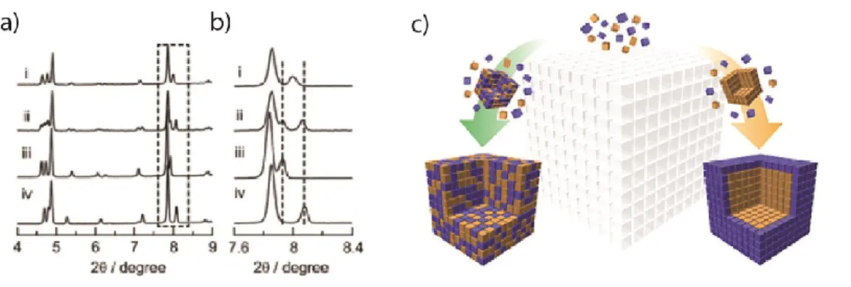
solutions are obtained when using sodium 5-nitroisophthalate as a precursor because it reacts very rapidly, but phase-separated products are found when the 5-nitroisophthalic acid is used (Fig. 2). The two different samples showed strikingly different adsorption behavior with methanol.
Figure 2. (a, b) Different distributions can be seen in the X-ray powder patterns. (c) Schematic showing the formation of solid solutions and phase-separated products. Adapted with permission from T. Fukushima et al,, J.
Am. Chem. Soc.134, 13341 (2012). Copyright 2012 American Chemical Society.
A second approach to the realization of mixed-metal MOFs leverages the ability to substitute one cation for another into an existing MOF, a process called transmetalation,6 that can create new functionality. It has been exploited quite extensively for optical materials where the levels of substitution that are needed are usually quite small. Rare-earth ions, especially Eu3+ and Tb3+, have been inserted at low levels (typically <3%) into Y3+, Gd3+ and Bi3+ containinghost frameworks to create photoluminescent materials that are suitable for use as phosphors. In an early example in glutarate (C5H6O43-) frameworks, Eu3+ was substituted for Gd3+ in
Gd(C5H6O4).nH2O phase and the photoluminscent lifetime studied as a function of the level of
water in the MOF channels.7 One of the attractions of MOFs for photoluminescence applications is that the organic ligands themselves can be used as sensitizers to absorb the excitation, as in the case of the Eu3+- and Tb3+-doped sodium/bismuth 1,4-benzenedicarboxylates, which show very good quantum efficiencies (Fig. 3).8
4
Figure 3. (a) Unit cell of sodium/bismuth 1,4-benzenedicarboxylate, which, when doped with Eu3+- and Tb3+- shows
(b) excellent luminescence in the red and green, respectively, when excited in the ultra violet. Adapted with permission from A. Thirumurugan, J.-C. Tan and A. K. Cheetham, Cryst. Growth & Design, 10, 1736 (2010). Copyright 2010 American Chemical Society.
Transmetalation, sometimes also called “post-synthetic metal exchange”,9 has also been used in the area of gas separation and storage to control adsorption and transport properties in porous MOFs. One such example is the use of Ti-exchanged UiO-66 [Zr6O6(OH)4(BDC)] to increase gas
permeability in mixed matrix membranes.10 It has also been shown that metal exchange can be used to obtain materials with topologies unreachable through solvothermal synthesis. One example is the case of MOFs based on the N,N’-bis(3,5-dicarboxyphenyl)pyromellitic diimide (H4BDCPPI) linker. Solvothermal synthesis yield materials with nbo and pts nets respectively, but
metal exchange from the copper-based material allowed Prasad et al. to obtain a Zn2(BDCPPI)
framework which retained pts topology.11
However, many systems that are superficially similar may show complex phase behaviour in reality. Transition metal succinates, for example, are notoriously fickle and yield complex results. In the case of the cobalt and nickel succinates (C4H4O42-), the two end-members have
different compositions and structures, Co5(OH)2(C4H4O4)4 and Ni7(OH)2(H2O)2(C4H4O4)6.2H2O,
respectively, when crystallized under the same conditions. At intermediate Co/Ni ratios, yet other compositions and structures are obtained: M4(OH)2(H2O)2(C4H4O4)3.2H2O and
M7(OH)2(H2O)2(C4H4O4)6.3.5H2O for 25% and 75% nickel, respectively (Fig. 4), with
disordered cations in each case.12
Figure 4. The cobalt/nickel succinates form four different structures with entirely different compositions when crystallized under the same conditions.Reprinted with permission from C. Livage et al, Angew. Chemie Intl. Ed. 46, 5877 (2007). Copyright 2007. John Wiley and Sons.
5
2.2 Amine cations in hybrid perovskites: substitution and disorder
Cations that can undergo substitution are not restricted to metallic ions. The hybrid perovskites, which some may consider MOF-type materials, of general formula [AmH]MIIX3, where Am is
an organic amine cation and X can be a wide range of anions, e.g. formate, azide, halide, borohydride,provide important examples (Fig. 5). The [AmH]PbIII3 frameworks are of great
current interest because of their outstanding performance as semiconductors in solar cells.13, 14 The most widely studied system is [CH3NH3]PbIII3, and it is possible to tune the band gap by
partially substituting the methylammonium cation by formamidinium, thereby increasing the efficiency to greater than 14%.15 This fine-tuning is normally achieved during the initial synthesis according to scheme (1), rather than by PSE.
Halide perovskites also exhibit disorder of a different nature: order-disorder transitions associated with hydrogen bonding between the amine hydrogens and the iodide anions.
[CH3NH3]PbIII3 itself, for example, is cubic above 330 K, tetragonal between 330 K and 160 K,
and orthorhombic below 160 K, due to progressive ordering of the methylammonium cations on lowering the temperature.16 However, unlike the analogous formate perovskites, the low
temperature, orthorhombic phase of [CH3NH3]PbIII3 is centrosymmetric and is therefore not a
ferroelectric.17
Figure 5. (a) Structure of the fully ordered hybrid perovskite, [(CH3)2NH2]CuII(HCOO)3.Reproduced from Ref. 18with permission from The American Physical Society (2013). (b) the hydrogen bonding between the amine cation
and the iodide anions in the A-site cavity of [CH3NH3]PbIII3. Reproduced from Ref. 19 with permission from The
Royal Society of Chemistry (2015).
Aside from the lead halide systems, the most widely studied class of the hybrid perovskites are the formates of general formula [AmH]MII(HCOO)3,20 which show a range of interesting
multiferroic behavior.21 Order-disorder transitions associated with hydrogen bonding again (Fig. 5) play a central role in determining the ferroelectric properties of these interesting systems. 22 It has been found recently that the formation of amine cation solid solutions of the type [AmH 1-xAm’Hx]]MII(HCOO)3,can be used to tune the ferroelectric phase transition, though there are
outstanding questions concerning the distribution of the two amines within individual grains and crystals.23
6
2.3. Mixed valence and cation vacancies in Metal-Organic Frameworks
Classical mixed valence behavior is rare in MOFs, and those cases that are known tend to have rational compositions where valence ordering can be achieved. The perovskite-related metal formate composition [NH2(CH3)2]FeIIFeIII(HCOO)6 is typical and has interesting magnetic
properties due to the charge ordering of Fe(II) and Fe(III).24 Similarly, it appears to be difficult to obtain non-stoichiometric MOFs where charge balance might be achieved by forming simple cation vacancies (vac). Thus, while mixed valence Fe1-xvacxO, which adopts the NaCl structure,
is well known and achieves charge balance by combining cation vacancies with Fe(II) and Fe(III), there are no well-documented examples of analogous MOFs, e.g. Fe1-xvacxL2-. Nor does
it seem possible to create cation vacancies by partial replacement of, say, a monovalent cation by a divalent one to form frameworks of the form Li2-xMgx/2vacx/2(L). This is unfortunate because
strategies such as this are used in lithium solid electrolytes to enhance cation mobility by creating vacancies into which the Li+ ions can move.
3. Ligand defects in metal-organic frameworks
The replacement of one organic ligand by another in MOFs is often more challenging than cation substitution because it is generally more difficult to match the coordinative and spatial
requirements of the substituted ligand than it is to match a simple cation. In this respect, porous MOFs are likely to be more accommodating towards ligand substitution and there has been extensive work in this area. Dense MOFs, on the other hand, have less space to accommodate differences in size.
3.1 Examples with anion or ligand substitution in porous MOFs
As with cation substitutions, partial anion or ligand substitution can be carried out during the initial synthesis or post-synthetically. We shall focus first on the latter category, and in particular on reactions that do not involve the replacement of the main linkers. Not surprisingly, it can be straightforward to replace ligands that are pendant rather than bridging. Thus, early work on layered phosphonates showed that it was possible to replace up to 60% of the phenylphosphonate ligands by phosphite without changing the layer spacing but nevertheless modulating the
intercalation chemistry.25 More recently, HKUST-1, a MOF that is formed from copper(II) paddlewheel dimers linked by 1,3,5-benzenetricarboxylate ligands, showed that the axial water molecules on the copper dimers could be replaced post-synthetically by pyridine, while the pyridine form could not be obtained by direct reaction.26 The removal of water ligands to create under-coordinated cation centers can be particularly advantageous for binding dihydrogen in hydrogen storage applications.27
Some of the first systematic studies of ligand functionalization in MOFs involved work by Cohen on post-synthetic modification (PSM) of 1,4-benzenedicarboxylate linkers in a series of common MOFs.28, 29 The linker itself was not replaced, but aromatic substituents such as -NH2
were exchanged for -CONH2 by means of PSM (Fig. 6). Alternatively, additional functionality
can be added to the aromatic linkers by introducing other reactants into an activated MOF. For example, Cr(CO)6 will react with benzene-containing linkers to attach Cr(CO)3 groups which can
7
Figure 6. A schematic representation of post synthetic modification in porous MOFs.Reproduced from Ref. 29 with
permission from The Royal Society of Chemistry.
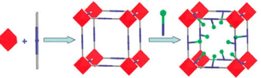
In a recent and very interesting variation on the above theme, the complete organic linker was exchanged in a process termed “Solvent Assisted Linker Exchange” (SALE).31 It was applied to the zeolitic imidazolate framework, ZIF-8 [Zn(C4H5N2)2] The use of SALE enabled the
exchange of the organic linker (2-methylimidazole) for a smaller one (imidazole, C3H3N2). The
resultant framework, SALEM-2, possessed very different sorption properties due to the opening of the pore-connecting apertures within the framework. Further functionalization using n-butyl lithium created active sites for BrØnsted base catalysis that could not be achieved in the parent
ZIF-8 (Fig. 7). Here again, as in transmetalation, post-synthetic linker substitution allows the synthesis of novel MOF materials with desirable function–property combinations, which could not be attained through direct solvothermal synthesis. Indeed, it has been shown, by
computational studies on the family of zeolitic imidazolate framework (ZIF) materials, that the thermodynamic stability of various polymorphs does not uniquely determine their experimental feasibility and accessibility through solvothermal synthesis.32, 33
Figure 7. Conversion of ZIF-8 to SALEM-2, followed by itsfunctionalization with n-butyl lithium. Reprinted with permission from O. Karagiaridi et al,, J. Am. Chem. Soc.134, 18790 (2012). Copyright 2012 American Chemical Society.
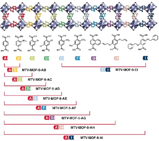
While the above examples have focused on cases where the modification of the MOF is done post-synthesis, there has been extensive work on systems where mixed ligands are incorporated during the initial synthesis (Scheme 1). One of the most detailed studies concerns the substitution of multiple combinations of substituted benzene dicarboxylate (BDC) – based ligands into the MOF-5 structure by Yaghi and co-workers.34 The scope is illustrated in Figure 8, which shows some of the many combinations of these so-called multivariate MOFs (in one case, as many as 8 different substituted linkers were introduced). As with other strategies for ligand substitution, one of the objectives is to create novel functionalities within a known structure type. In this particular work, it was possible to substantially enhance the CO2 adsorption capacity by
8
Figure 8. Various permutations of 1,4-BDC derivatives in the MOF-5 structure type. From H. X. Deng et al, Science, 327, 846 (2010). Reprinted with permission from AAAS.
Work by Kitagawa and others focused specifically on flexible frameworks, and endeavored to tune the flexibility in order to optimize sorption performance.35, 36In one example, two doubly interdigitated frameworks – [Zn(5-NO2-ip)(bpy)(0.5DMF·0.5MeOH)] and
[Zn(5-MeO-ip)(bpy)](0.5DMF·0.5MeOH), where ip = 5-nitroisophthalate and bpy = 4,4’-bipyridyl were prepared, giving two closely related structures with similar lattice parameters. However, the guest-free structures were very different after desolvation. The former shows a porous to non-porous transition on degassing (and gate-opening on adsorption), whereas the latter remains in the open form. Ligand-based solid solutions were then prepared and the two substituents appeared to be homogeneously distributed in the as-synthesized samples. The adsorption properties of the degassed samples were then explored and it was found that the gate-opening transition could be fine-tuned by adjusting the composition of the solid solutions, giving rise to enhanced
performance for the adsorption of CO2 from CO2/CH4 mixtures.
3.2 Examples of anion substitution in dense MOFs
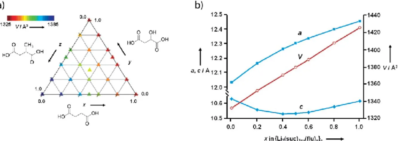
Recent work on lithium succinates and related systems37 illustrate what can be achieved in this area. The three dense MOFs - lithium succinate, lithium hydroxysuccinate (i.e. malate) and lithium methylsuccinate - turn out to be isostructural, in spite of the different sizes of their ligands. There is no solvent-accessible volume, but the different ligands can still be accommodated; indeed, the Young’s modulus of the succinate is only 20 GPa, which is
comparable to many porous MOFs. Mixed samples were synthesized by mechanical milling in order to avoid the problems with differential crystallization rates, and complete solid solution was found throughout the ternary phase diagram (Fig. 9a). This was confirmed Le Bail
9
Figure 9. (a) Ternary phase diagram shows solid solutions from lithium succinate and related phases. (b) The succinate-tetrafluorsuccinate system obeys Vegard’s Law throughout its composition range.Reprinted with permission from H. H. M. Yeung et al, Angew. Chemie Intl. Ed. 52, 5544 (2013). Copyright 2013. John Wiley and Sons.
Surprisingly, even the tetrafluorinated succinate ligand can be incorporated into the succinate structure and a complete solid solution can be obtained (Fig. 9b). A 50:50 sample in the lithium succinate-tetrafluorosuccinate solid solution was analyzed in greater detail in order to confirm that the two ligands are homogeneously distributed. Both full Rietveld refinement with
synchrotron PXRD data (Fig. 9b), infrared analysis, and spin diffusion solid-state NMR measurements confirmed that the two ligands were well mixed at the molecular level.37
Interestingly, the flexibility of lithium succinate and related phases provides a rare example of solid solution formation by post-synthesis modification in a dense MOF. Thus, in the specific case of lithium hydroxysuccinate (i.e. malate), it is possible to perform a topotactic dehydration across the C-C bond to form the corresponding fumarate phase.38In fact, 80% of the water can be removed from a crystal without loss of crystallinity, and the process has been followed by in situ single crystal X-ray diffractometry. Density functional theory (DFT) calculations show that the fumarate thus formed is a metastable phase, that is 12.7 kJ/mol less stable than the normal form.
3.3 Other types of anion defects in MOFs
The above sections have dealt with conventional ligand defects where one ligand, typically a bridging anion, is replaced by another one. There are, however, other possibilities, such as replacing a bridging ligand by two monodentate ones, and this type of defect has been incorporated into porous, pillared diphosphonates, including the widely studied zirconium diphosphonates.39 For example, in the case of Al2[O3PC2H4PO3](H2O)2F2, it has proved possible
to replace some of the ethylene diphophonic acid pillars by two phosphite groups to form
Al2[(O3PC2H4PO3)1-x(HPO3)2x](H2O)2F2 solid solutions. Up to 32% of the pillars can be replaced
and the distribution of the defects appears to be homogeneous. Such tuning enables the adsorption and desorption properties of the MOF to be modulated.40
The same strategy has been used to replace a dicarboxylate such as 1,4-BDC by monocarboxylate anions, thus removing the bridge between the cations and creating two dangling ligands.41, 42 This has been reported for UiO-66(Zr or Hf), a MOF that contains octahedral zirconium (or hafnium) clusters that are linked by 1,4-BDC ligands to form a highly porous structure. It has recently been shown that pairs of trifluoroacetate (TFA) groups can replace individual 1,4-BDC linkers and that such substitution results in enhanced Lewis acidity for catalytic reactions.43 In an interesting extension of this theme, it has also been demonstrated that the removal of linkers by such
substitution can enhance the mechanical stability of UiO-66, as shown by the improved resistance to amorphization during milling.44This rather counter-intuitive behavior is ascribed to the
strengthening of the zirconium-carboxylate bonds due to the local electron withdrawing effect of the TFA.
10
4. Domain structures in MOFs
To a first approximation, the various defects described above are generally thought to be randomly-distributed throughout a given framework. In conventional inorganic solids, such a picture is only sometimes true. For example, Schottky defects do not correlate strongly in NaCl but can be so robustly ordered in transition metal oxides that in the case of NbO they even break the lattice symmetry.45 Understanding the extent to which defects are correlated in MOFs may prove important for a number of reasons. Wherever defects are associated with transport properties (e.g. acid sites for proton conductivity, or vacancy sites for gas storage), percolation will depend critically on the existence and nature of correlated defect positioning. Moreover, the dynamical and elastic properties of MOFs are also sensitive to the presence of domain structures, which influence directly the underlying phonon dispersion. And, although a significant challenge, the controlled arrangement of multiple defects might eventually enable design of protein-like “active sites” for catalytically-active MOFs.46
Perhaps the clearest indication that MOFs can support correlated defects comes from the structural chemistry of the UiO-66 family.47 The parent compound is usually prepared under basic
conditions from a mixture of ZrCl4 and H2bdc, but addition of monocarboxylate “modulators”
leads to a defective framework structure in which some of the bdc linkers have been replaced by modulator pairs [Fig. 10].48 Varying the modulator chemistry and concentration determines the density of defects introduced. Because these defects must always occur in pairs, it has always been known that there must be at least local correlations between defect sites. However, most of the experimental and computational approaches used to characterise these defects are insensitive to the longer-range defect correlations associated with domain formation.48, 49 Even detailed single-crystal X-ray diffraction studies have determined only the total defect concentration and the geometry of individual defect sites.50 This is because conventional single-crystal analysis is insensitive to long-range correlations if those correlations are not sufficiently strong to force periodic patterning (e.g. of defects). Instead the experimental methods most sensitive to defect correlations are diffuse scattering measurements - X-ray, neutron, or electron; powder or single-crystal and electron microscopy.51 These are precisely the methods which have informed much of our understanding of collective defect structures in conventional inorganic materials such as zeolites and transition-metal oxides.52, 53 We note that electron microscopy is the least translatable of these methods to the study of MOFs since so many systems are terminally sensitive to the electron beam.54
Figure 10. The structure of non-defective UiO-66 is comprised of [ZrO4(OH)4] clusters connected by terephthalate
linkers. The metal-containing clusters of the resulting framework are arranged on a face-centred cubic lattice. (b) Inclusion during framework synthesis of monocarboxylate modulators, such as formate as shown here, can lead to correlated linker vacancies where a single terephthlate linker is replaced by two monocarboxylates in an opposing geometry.
11
Structured diffuse scattering characteristic of defect nanodomains was first observed in the Hf-containing analogue UiO-66(Hf), prepared using high concentrations of formic acid modulator. The X-ray diffraction patterns of these samples include a series of diffuse scattering peaks at positions forbidden by the symmetry of the parent UiO-66 structure (space group F43m).55 That this diffuse scattering is associated with defects rather than solvent ordering as originally
suggested is evident in their persistence on thermal desolvation. Intriguingly, defect structure models which consider only linker/modulator substitution cannot reproduce the observed diffuse scattering intensities. Instead a model in which vacancies at the entire [Hf6O4(OH)4] cluster site
are correlated to form defect nanoregions with reduced symmetry (space group P43m) quantitatively accounts for the diffuse scattering [Fig. 11].56 There is a strong analogy to the Schottky defect structure of the transition-metal monoxides with the cluster vacancy arrangement in defect nanoregions mapping directly onto the Nb vacancy sites in NbO.57 This model was
supported by electron diffraction, X-ray pair distribution function and anomalous X-ray diffraction measurements, the latter showing conclusively that defects in UiO-66(Hf) involve modulation in Hf concentrations.56
Figure 11. (a) Reproduced from reference 56. The X-ray powder diffraction pattern of d-UiO-66(Hf) contains a series
of weak diffuse reflections that are forbidden by the symmetry of the parent structure. (b) These reflections are evident in selected area electron diffraction patterns of individual d-UiO-66(Hf) crystallites. (c) The fundamental unit of the domain structure in this material has cluster vacancies at the corner of the unit cell and has primitive cubic symmetry. (d) These primitive cells coexist with regions of the parent face-centred cubic structure, facilitated by the close match in unit cell metric. (d) Because the face-centred cubic lattice can be understood in terms of four
interpenetrating primitive cubic lattices, there are four possible orientations for the defect nanodomains. In the bulk d-UiO-66(Hf) structure all four of these occur (here shown using different colours). This model of the domain structure was used to calculate the diffraction pattern shown in panel (a).
12
Cluster vacancies are not unique to the Hf-containing UiOs. Surface area measurements for a number of defective Zr-containing UiO-66 variants are consistent only with the existence of [Zr6O4(OH)4] cluster vacancies.41 Likewise, doping of UiO-66(Zr) with Ce gives rise to a series of
defective frameworks whose diffraction patterns contain the same characteristic diffuse scattering peaks observed for UiO-66(Hf).58 As in the Hf MOFs, this scattering persists on thermal
desolvation suggesting that it also arises from nanodomains of correlated cluster vacancies. An extreme example of correlated defects in this structural family has recently been discovered in a 2-sulfoterephthalate-bridged Zr-containing UiO-66 analogue.59 The structure of this sulfonated MOF is characterised by a (~40 Å)3 unit cell in which 3/16 of the Zr cluster sites are vacant. The
vacancy ordering observed experimentally can be considered a periodic intermediate lying between the defect-free UiO-66 parent and the P43mdomain structure of UiO-66(Hf), where the cluster vacancy fraction is 1/4 [Fig. 12].
Figure 12. (a) The face-centred cubic structure of defect-free UiO-66. (b) The 2-sulfoterephthalate UiO-66 derivative reported in reference 59 has a body-centred cubic structure with a lattice parameter twice that of the parent structure
shown in (a). Cluster vacancies order at the edges of this enlarged unit cell. (c) The primitive cubic structure of the defect domains in d-UiO-66(Hf), which is related to the cell shown in (b) on removal of the clusters at the corners of that unit cell (shown here in blue).
Already there are indications that these correlated defect structures in UiO frameworks result in interesting physical and chemical properties. In Ce-doped UiO-66(Zr), linker vacancies are coupled to Ce4+/3+ reduction, which in turn promotes catalytic performance in methanol
oxidation.58 A similar conclusion was reached in Ref.41, where defect sites promoted uptake of catalytically-active Cr3+ centers during post-synthetic modification. The fractal-like network of exposed defect sites in the sulfonated MOF of Ref. 59 is thought to be responsible for its extremely high proton conductivity. And, finally, the concentration of correlated cluster vacancies in
defective UiO-66(Hf) samples was shown found to influence their thermal expansion behaviour, which can include the desirable property of “colossal” negative thermal expansion.60
It is not yet clear whether strongly-correlated defects are unique to the UiO family of MOFs. Certainly the strong X-ray scattering contrast of absent vs present [M6O4(OH)4] clusters means
that defect correlations have a clearer experimental signature for this system than is likely for other defective MOF families. Nevertheless there are at least three reasons why the UiO family might be particularly prone to defect inclusion and then to the existence of correlations between those defects to form domain structures. First, the parent network has a very high connectivity, which means that linker/cluster vacancies can be incorporated while maintaining mechanical stability. Second, the unit cell parameters calculated for defect-free and defect structures differ by only 0.05%, and so defects can be incorporated without significant lattice strains.59 Third, the core [M6O4(OH)4(OR)12] building unit is susceptible to symmetry-lowering distortions that may play a
role in driving defect correlations. The idealised Td point symmetry of the cluster lowers
spontaneously to D2d (≡ tetragonal 42m) in the crystal structures of non-bridging cluster packings
(e.g. M = Hf, R = CH3; Refs.56, 61) in a way that is reminiscent both of symmetry lowering in the
transition-metal acetate paddle-wheels and indeed of Jahn Teller effects in general [Fig. 13].62 This susceptibility to symmetry lowering suggests that modulator substitution at the four
equatorial sites of a [M6O4(OH)4(OR)12] cluster during MOF growth allows local relaxation. Then,
because this local distortion can only be propagated on the NbO-type defect lattice,63 the experimentally-observed domain structure emerges naturally.
13
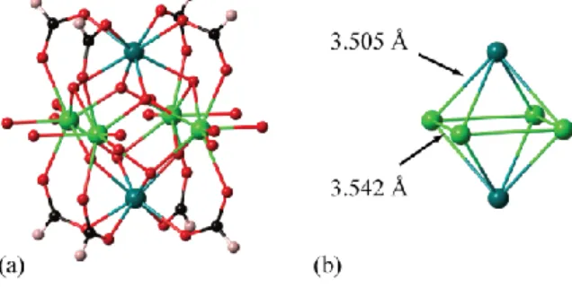
Figure 13. (a) Representation of the Zr6 cluster geometry found in the zirconium formate compound
Zr6O4(OH)4(HCOO)8.61 The equatorial oxygen atoms belong to dangling formate anions, and are disordered over
closely-related sites. The two crystallographically-distinct Zr atoms are shown in different shades of green. (b) The central Zr6 octahedron geometry in this cluster, showing the spontaneous symmetry-lowering of Zr...Zr distances.
Our understanding of the microscopic driving forces responsible for defect correlations in MOFs would be improved enormously by an increased diversity of experimentally-characterised systems for which domain structures occur. The increased application of diffuse scattering and electron microscopy methods to the study of MOFs will be critical in this sense. Indeed, experience
suggests that the presence of structured diffuse scattering in MOF single crystal diffraction studies is probably more widespread than has been reported in the literature. A recent study of the
relationship between correlated defect structures relevant to MOF networks and the corresponding diffuse scattering patterns64 demonstrates that the signature of domain structures in the parent Bragg reflections can often be subtle, but the existence of characteristic diffuse scattering may prove invaluable in diagnosing correlated disorder of the type discussed here. A number of known MOF structures, such as the intriguing example of “partial interpenetration” in NOTT-202,65 may benefit from reanalysis in this context.
5. Amorphous solids, liquids and melt-quenched glasses
Arguably the clearest examples of disordered materials, those which lack any long range order (i.e. those which are amorphous) are easily identifiable from the absence of Bragg peaks in their X-ray diffraction patterns. In the context of MOFs and coordination polymers, such structures can, like cation substitution in solid solutions, be formed through (i) alteration of initial synthetic conditions, or (ii) through post synthetic introduction of disorder.
5.1 Metal-organic frameworks
Fast crystallization kinetics lie behind the propensity of MOF precursors to self-assemble into highly ordered networks during synthesis.66 Highly disordered products, such as amorphous solids, are hence difficult to form directly, though differential formation of crystalline and amorphous states of a zeolite-related MOF of composition Zn(C4H3N2O)2 can be effected by
altering the rate of addition of a structure directing agent to the initial metal and organic containing solution.67 More commonly, heating or mechanical impact are used to irreversibly introduce disorder into crystalline hybrid materials.
The application of mechanosynthesis to crystalline, non-solvated zinc imidazolate frameworks (ZIFs) results in formation of stable amorphous network arrangements. 68 However, a recent example on the in-situ ball-milling of ZIF-8 in an aqueous acidic environment,69 found not only the expected amorphization, but subsequent recrystallization of the amorphous network upon continued milling, to a previously unidentified topology. The metastable nature of some amorphous MOF phases is also evidenced in the crystalline-amorphous-crystalline transition sequence upon heating of ZIF-4,70 a three-dimensional framework of Zn(C3H3N2) composition
formed of tetrahedral Zn2+ nodes connected by bidentate imidazolate ligands. Here, after formation of an amorphous solid at 300 °C by heating of the crystalline phase, recrystallization to the dense ‘ZIF-zni’ MOF is observed at 450 °C. In this case, knowledge of the chemical composition of the amorphous phase (the transition sequence not being accompanied by mass loss), allowed total scattering data on the amorphous phase to be modeled by Reverse Monte-Carlo techniques.70
14
Furthermore, whilst MOFs are usually observed to decompose to oxides at high temperatures, the dense ZIF-zni was observed to undergo melting at 580 °C;71 the first example of the melting of a three-dimensional MOF. This observation was rationalized in terms of the accessibility of the intrinsic melting point of ZIF-zni, made possible by the raising of the point of thermal decomposition to over 600 °C, by excluding air from the heating process.
Cooling of the liquid back to room temperature yielded a glass, which contained both tetrahedral Zn2+ centers and Zn-Zn pairs separated by bidentate ligands, reminiscent of the crystalline phase (Fig. 14). The different network connectivity of crystal and glass phases suggested a
reconstructive transition during melting and cooling, due to Zn-N dissociation in the disordering mechanism. Such dissociation would, in turn, infer ionic liquid formation upon melting, though no investigations into this phase were performed. An alternative explanation, analogous to that used to explain the melting (at much higher temperatures) of inorganic zeolites, involves dihedral angle changes.
Figure 14. Dimensionality of coordination polymers and MOFs known to undergo structural melting. (a) [Zn(HPO4)(H2PO4)2].2C3H5N2.(b) [Zn(H2PO4)2(HTr)2]n.72 (c) [Zn(C3H3N2)2]. Adapted with permission from
Umeyama, D.; Horike, S.; Inukai, M.; Itakura, T.; Kitagawa, S. J. Am. Chem. Soc. 2015, 137, 864., and Umeyama, D.; Horike, S.; Inukai, M.; Itakura, T.; Kitagawa, S. J. Am. Chem. Soc. 2012, 134, 12780. Copyright 2015 and 2012 American Chemical Society respectively.
5.2 1D and 2D coordination polymers
Lower dimensionality hybrid structures have also been observed to melt. The one dimensional coordination polymer, [Zn(HPO4)(H2PO4)2].2C3H5N2, consists of chains of four-fold coordinated
Zn2+ centers linked by phosphate ligands, along with charge-compensating protonated imidazole
species. At the same time as the example presented above, work on this system revealed a solid-liquid transition at 150 °C, in a process set off by the excessive disordering and eventual
dissociation of one Zn-O bond in the Zn2+ coordination sphere. 73 Cooling led to glass formation, with dynamic mechanical analysis, 31P nuclear magnetic resonance spectroscopy, pair
distribution function (PDF) and X-ray absorption spectroscopy studies (XAS) on the crystalline and glass solids confirming the absence of Zn-O association in the liquid state. Furthermore, the glass itself was deduced to have a one-dimensional structure, like that of the crystal. Work on another 1D polymer incorporating octahedral Zn2+ centers, [Zn3(H2PO4)6(H2O)3].C7H7N2, also
led to liquid formation, though at a lower temperature of 100 °C . In this case however,
significantly faster recrystallization rates of the resultant ionic liquid prevented glass formation at room temperature.
15
In possessing similar immediate inorganic coordination environments in both crystal and glasses, the above systems share common features with other glass formers, including zeolites.74 A system of intermediate two dimensional connectivity, [Zn(H2PO4)2(HTr)2]n ,75 which melts at
184 °C, does however undergo network connectivity changes on the solid-glass transformation. In the structure, each organic ligand equatorially bridges Zn2+ ions to form layers, with an octahedral coordination environment completed by non-bridging phosphate ions in the axial positions. The process again involved bond dissociation, however, unusually, reformation of an extended network was not observed upon glass formation. PDF and XAS studies were used to derive a molecular model for the end glass state, a transition driven by the preference of Zn2+ ions for a 4-fold coordination environment.
6. Concluding Remarks
The concepts of defects and disorder are inextricably linked with one another. Point vacancies, substitutional defects and long-range disorder may all be introduced into MOFs pre-, or post synthetically. Whilst at present still system dependent, notable studies of changing both the physical and chemical behavior of known frameworks using the methodologies presented here exist. Such work hints that perhaps we might make equal, if not greater, advances in the field by looking to change the properties of existing structures in a controlled manner, as opposed to synthesizing new structures and characterizing their properties.
Acknowledgements
The authors would like to thank Ras Al Khaimah Center for Advanced Materials (AKC, TDB), Trinity Hall (TDB), and the ERC (ALG, Grant 279705).
Notes
The authors declare no competing financial interests.
References
1. Z. L. Fang, B. Bueken, D. E. De Vos and R. A. Fischer, Angew. Chem. Int. Ed., 2015, 54, 7234-7254.
2. C. Wagner and W. Schottky, Z Phys Chem B-Chem E, 1930, 11, 163-210.
3. L. N. Appelhans, M. Kosa, A. V. Radha, P. Simoncic, A. Navrotsky, M. Parrinello and A. K. Cheetham, J. Am. Chem. Soc., 2009, 131, 15375-15386.
4. M. Kim, J. F. Cahill, H. H. Fei, K. A. Prather and S. M. Cohen, J. Am. Chem. Soc., 2012, 134, 18082-18088.
5. T. Fukushima, S. Horike, H. Kobayashi, M. Tsujimoto, S. Isoda, M. L. Foo, Y. Kubota, M. Takata and S. Kitagawa, J. Am. Chem. Soc., 2012, 134, 13341-13347.
6. M. Lalonde, W. Bury, O. Karagiaridi, Z. Brown, J. T. Hupp and O. K. Farha, J Mater Chem A, 2013, 1, 5453-5468.
7. F. Serpaggi, T. Luxbacher, A. K. Cheetham and G. Ferey, J Solid State Chem, 1999, 145, 580-586.
8. A. Thirumurugan, J. C. Tan and A. K. Cheetham, Cryst. Growth. Des., 2010, 10, 1736-1741.
9. C. K. Brozek and M. Dinca, J. Am. Chem. Soc., 2013, 135, 12886-12891. 10. C. H. Lau, R. Babarao and M. R. Hill, Chem. Commun., 2013, 49, 3634-3636. 11. T. K. Prasad, D. H. Hong and M. P. Suh, Chem.-Eur. J., 2010, 16, 14043-14050.
12. C. Livage, P. M. Forster, N. Guillou, M. M. Tafoya, A. K. Cheetham and G. Ferey, Angew. Chem. Int. Ed., 2007, 46, 5877-5879.
13. P. Qin, S. Tanaka, S. Ito, N. Tetreault, K. Manabe, H. Nishino, M. K. Nazeeruddin and M. Gratzel, Nat Commun, 2014, 5.
16
14. H. J. Snaith, J. Phys. Chem. Lett., 2013, 4, 3623-3630.
15. G. E. Eperon, S. D. Stranks, C. Menelaou, M. B. Johnston, L. M. Herz and H. J. Snaith, Energ Environ Sci, 2014, 7, 982-988.
16. C. C. Stoumpos, C. D. Malliakas and M. G. Kanatzidis, Inorg. Chem., 2013, 52, 9019-9038.
17. T. Baikie, Y. N. Fang, J. M. Kadro, M. Schreyer, F. X. Wei, S. G. Mhaisalkar, M. Graetzel and T. J. White, J Mater Chem A, 2013, 1, 5628-5641.
18. Z. X. Wang, P. Jain, K. Y. Choi, J. van Tol, A. K. Cheetham, H. W. Kroto, H. J. Koo, H. Zhou, J. M. Hwang, E. S. Choi, M. H. Whangbo and N. S. Dalal, Phys. Rev. B., 2013, 87. 19. J. H. Lee, N. C. Bristowe, P. D. Bristowe and A. K. Cheetham, Chem. Commun., 2015,
51, 6434-6437.
20. X. Y. Wang, L. Gan, S. W. Zhang and S. Gao, Inorg. Chem., 2004, 43, 4615-4625.
21. P. Jain, V. Ramachandran, R. J. Clark, H. D. Zhou, B. H. Toby, N. S. Dalal, H. W. Kroto and A. K. Cheetham, J. Am. Chem. Soc., 2009, 131, 13625-13627.
22. T. Besara, P. Jain, N. S. Dalal, P. L. Kuhns, A. P. Reyes, H. W. Kroto and A. K. Cheetham, Proc. Natl. Acad. Sci. U.S.A., 2011, 108, 6828-6832.
23. S. Chen, R. Shang, B. W. Wang, Z. M. Wang and S. Gao, Angew. Chem. Int. Ed., 2015, 54, 11093-11096.
24. J. P. Zhao, B. W. Hu, F. Lloret, J. Tao, Q. A. Yang, X. F. Zhang and X. H. Bu, Inorg. Chem., 2010, 49, 10390-10399.
25. K. J. Scott, Y. Zhang, R. C. Wang and A. Clearfield, Chem. Mater., 1995, 7, 1095-1102. 26. S. S. Y. Chui, S. M. F. Lo, J. P. H. Charmant, A. G. Orpen and I. D. Williams, Science,
1999, 283, 1148-1150.
27. M. Dinca, A. Dailly, Y. Liu, C. M. Brown, D. A. Neumann and J. R. Long, J. Am. Chem. Soc., 2006, 128, 16876-16883.
28. Z. Q. Wang and S. M. Cohen, J. Am. Chem. Soc., 2007, 129, 12368-12369. 29. Z. Q. Wang and S. M. Cohen, Chem. Soc. Rev., 2009, 38, 1315-1329.
30. S. S. Kaye, H. J. Choi and J. R. Long, J. Am. Chem. Soc., 2008, 130, 16921-16925. 31. O. Karagiaridi, M. B. Lalonde, W. Bury, A. A. Sarjeant, O. K. Farha and J. T. Hupp, J. Am.
Chem. Soc., 2012, 134, 18790-18796.
32. D. W. Lewis, A. R. Ruiz-Salvador, A. Gomez, L. M. Rodriguez-Albelo, F. X. Coudert, B. Slater, A. K. Cheetham and C. Mellot-Draznieks, CrystEngComm, 2009, 11, 2272-2276. 33. J. A. Gee and D. S. Sholl, J Phys Chem C, 2013, 117, 20636-20642.
34. H. X. Deng, C. J. Doonan, H. Furukawa, R. B. Ferreira, J. Towne, C. B. Knobler, B. Wang and O. M. Yaghi, Science, 2010, 327, 846-850.
35. T. Fukushima, S. Horike, Y. Inubushi, K. Nakagawa, Y. Kubota, M. Takata and S. Kitagawa, Angew. Chem. Int. Ed., 2010, 49, 4820-4824.
36. M. Kim, J. A. Boissonnault, P. V. Dau and S. M. Cohen, Angew. Chem. Int. Ed., 2011, 50, 12193-12196.
37. H. H. M. Yeung, W. Li, P. J. Saines, T. K. J. Koster, C. P. Grey and A. K. Cheetham, Angew. Chem. Int. Ed., 2013, 52, 5544-5547.
38. H. H. M. Yeung, M. Kosa, J. M. Griffin, C. P. Grey, D. T. Major and A. K. Cheetham, Chem. Commun., 2014, 50, 13292-13295.
39. G. Alberti, F. Marmottini, S. Murciamascaros and R. Vivani, Angew Chem Int Edit, 1994, 33, 1594-1597.
40. H. G. Harvey, J. Hu and M. P. Attfield, Chem. Mater., 2003, 15, 179-188.
41. O. V. Gutov, M. G. Hevia, E. C. Escudero-Adan and A. Shafir, Inorg. Chem., 2015, 54, 8396-8400.
42. M. Vandichel, J. Hajek, F. Vermoortele, M. Waroquier, D. De Vos and Speybroeck, CrystEngComm, 2015, 17, 395-406.
43. F. Vermoortele, B. Bueken, G. Le Bars, B. Van de Voorde, M. Vandichel, K. Houthoofd, A. Vimont, M. Daturi, M. Waroquier, V. Van Speybroeck, C. Kirschhock and D. E. De Vos, J. Am. Chem. Soc., 2013, 135, 11465-11468.
44. B. Van de Voorde, I. Stassen, B. Bueken, F. Vermoortele, D. De Vos, R. Ameloot, J. C. Tan and T. D. Bennett, J Mater Chem A, 2015, 3, 1737 - 1342.
45. J. K. Burdett and J. F. Mitchell, Prog Solid State Ch, 1995, 23, 131-170. 46. A. B. Cairns and A. L. Goodwin, Chem. Soc. Rev., 2013, 42, 4881-4893.
47. J. H. Cavka, S. Jakobsen, U. Olsbye, N. Guillou, C. Lamberti, S. Bordiga and K. P. Lillerud, J. Am. Chem. Soc., 2008, 130, 13850-13851.
48. L. Valenzano, B. Civalleri, S. Chavan, S. Bordiga, M. H. Nilsen, S. Jakobsen, K. P. Lillerud and C. Lamberti, Chem. Mater., 2011, 23, 1700-1718.
17
49. H. Wu, Y. S. Chua, V. Krungleviciute, M. Tyagi, P. Chen, T. Yildirim and W. Zhou, J. Am. Chem. Soc., 2013, 135, 10525-10532.
50. C. A. Trickett, K. J. Gagnon, S. Lee, F. Gandara, H. B. Bürgi and O. Yaghi, Angew. Chem. Int. Ed., 2015, 54, 1-7.
51. D. A. Keen and A. L. Goodwin, Nature, 2015, 521, 303-309. 52. R. L. Withers, Z Kristallogr, 2005, 220, 1027-1034.
53. T. Willhammar, J. L. Sun, W. Wan, P. Oleynikov, D. L. Zhang, X. D. Zou, M. Moliner, J. Gonzalez, C. Martinez, F. Rey and A. Corma, Nat Chem, 2012, 4, 188-194.
54. D. S. Sholl and R. P. Lively, J. Phys. Chem. Lett., 2015, 6, 3437-3444.
55. S. Jakobsen, D. Gianolio, D. S. Wragg, M. H. Nilsen, H. Emerich, S. Bordiga, C. Lamberti, U. Olsbye, M. Tilset and K. P. Lillerud, Phys. Rev. B., 2012, 86, 125429.
56. M. J. Cliffe, W. Wan, X. D. Zou, P. A. Chater, A. K. Kleppe, M. G. Tucker, H. Wilhelm, N. P. Funnell, F. X. Coudert and A. L. Goodwin, Nat Commun, 2014, 5, 4176.
57. J. K. Burdett and J. F. Mitchell, Inorg. Chem., 1993, 32, 5004-5006.
58. F. Nouar, M. I. Breeze, B. C. Campo, A. Vimont, G. Clet, M. Daturi, T. Devic, R. I. Walton and C. Serre, Chem. Commun., 2015, 51, 14458-14461.
59. J. M. Taylor, T. Komatsu, S. Dekura, K. Otsubo, M. Takata and H. Kitagawa, J. Am. Chem. Soc., 2015, 137, 11498-11506.
60. M. J. Cliffe, J. A. Hill, C. A. Murray, F. X. Coudert and A. L. Goodwin, Phys Chem Chem Phys, 2015, 17, 11586-11592.
61. W. B. Liang, R. Babarao, M. J. Murray and D. M. D'Alessandro, Dalton Trans, 2015, 44, 1516-1519.
62. V. K. Peterson, G. J. Kearley, Y. Wu, A. J. Ramirez-Cuesta, E. Kemner and C. J. Kepert, Angew. Chem. Int. Ed., 2010, 49, 585-588.
63. A. F. Wells, Structural Inorganic Chemistry, Clarendon Press, Oxford, 1984.
64. A. R. Overy, A. B. Cairns, M. J. Cliffe, M. G. Tucker and A. L. Goodwin, Nat Commun, 2015, In-press.
65. S. H. Yang, X. Lin, W. Lewis, M. Suyetin, E. Bichoutskaia, J. E. Parker, C. C. Tang, D. R. Allan, P. J. Rizkallah, P. Hubberstey, N. R. Champness, K. M. Thomas, A. J. Blake and M. Schroder, Nat. Mater., 2012, 11, 710-716.
66. N. Stock and S. Biswas, Chem. Rev., 2012, 112, 933-969.
67. Z. F. Xin, X. S. Chen, Q. Wang, Q. Chen and Q. F. Zhang, Micropor. Mesopor. Mat., 2013, 169, 218-221.
68. T. D. Bennett and A. K. Cheetham, Acc. Chem. Res., 2014, 47, 1555-1562.
69. A. D. Katsenis, A. Puskaric, V. Strukil, C. Mottillo, P. A. Julien, K. Uzarevic, M. H. Pham, T. O. Do, S. A. J. Kimber, P. Lazic, O. Magdysyuk, R. E. Dinnebier, I. Halasz and T. Friscic, Nat Commun, 2015, 6, 6662.
70. T. D. Bennett, A. L. Goodwin, M. T. Dove, D. A. Keen, M. G. Tucker, E. R. Barney, A. K. Soper, E. G. Bithell, J. C. Tan and A. K. Cheetham, Phys. Rev. Lett., 2010, 104, 115503. 71. T. D. Bennett, J. C. Tan, Y. Z. Yue, E. Baxter, C. D. Ducati, N. Terril, H. Y. Yeung, Z.
Zhou, W. Chen, S. Henke, A. K. Cheetham and G. N. Greaves, Nat Commun, 2015, 6, 8079.
72. D. Umeyama, S. Horike, M. Inukai, T. Itakura and S. Kitagawa, J. Am. Chem. Soc., 2012, 134, 12780-12785.
73. D. Umeyama, S. Horike, M. Inukai, T. Itakura and S. Kitagawa, J. Am. Chem. Soc., 2015, 137, 864-870.
74. G. N. Greaves and S. Sen, Adv. Phys., 2007, 56, 1-166.

![Figure 5. (a) Structure of the fully ordered hybrid perovskite, [(CH 3 ) 2 NH 2 ]Cu II (HCOO) 3](https://thumb-eu.123doks.com/thumbv2/123doknet/7762587.255373/6.892.111.613.500.746/figure-structure-fully-ordered-hybrid-perovskite-ch-hcoo.webp)
![Figure 10. The structure of non-defective UiO-66 is comprised of [ZrO 4 (OH) 4 ] clusters connected by terephthalate linkers](https://thumb-eu.123doks.com/thumbv2/123doknet/7762587.255373/11.892.253.575.823.1030/figure-structure-defective-comprised-clusters-connected-terephthalate-linkers.webp)