O
pen
A
rchive
T
OULOUSE
A
rchive
O
uverte (
OATAO
)
OATAO is an open access repository that collects the work of Toulouse researchers and
makes it freely available over the web where possible.
This is an author-deposited version published in :
http://oatao.univ-toulouse.fr/
Eprints ID : 13864
To link to this article : DOI: 10.1016/j.jfluidstructs.2014.09.005
URL :
http://dx.doi.org/10.1016/j.jfluidstructs.2014.09.005
To cite this version : Bourguet, Rémi and Karniadakis, George E. and
Triantafyllou, Michael S. On the validity of the independence
principle applied to the vortex-induced vibrations of a flexible
cylinder inclined at 60 degrees. (2014) Journal of Fluids and
Structures, vol. 53. pp. 58-69. ISSN 0889-9746
Any correspondance concerning this service should be sent to the repository
administrator:
[email protected]
On the validity of the independence principle applied to the
vortex-induced vibrations of a flexible cylinder inclined at 601
Rémi Bourguet
a,n, George Em Karniadakis
b, Michael S. Triantafyllou
caInstitut de Mécanique des Fluides de Toulouse, Université de Toulouse and CNRS, Toulouse 31400, France bDivision of Applied Mathematics, Brown University, Providence, RI 02912, USA
cDepartment of Mechanical Engineering, Massachusetts Institute of Technology, Cambridge, MA 02139, USA
a b s t r a c t
The vortex-induced vibrations (VIV) of a flexible cylinder inclined at 601 are investigated by means of direct numerical simulation, at a Reynolds number equal to 500, based on the cylinder diameter and inflow velocity. The cylinder has a circular cross-section and a length to diameter aspect ratio equal to 50; it is modeled as a tension-dominated structure which is free to oscillate in the in-line and cross-flow directions. The behavior of the coupled fluid–structure system is examined for two values of the tension. Particular attention is paid to the validity of the independence principle (IP) which states that the inclined and normal-incidence body cases are comparable if the inflow velocity normal component is used to scale the physical quantities.
The flexible cylinder exhibits regular VIV for both values of the tension. In the high-tension configuration, where the in-line bending of the structure remains small, the IP is shown to be valid for the prediction of the cylinder responses and the fluid forces. In contrast, in the lower-tension configuration, the behavior of the fluid–structure system deviates from the IP. It is shown that this deviation is connected to the larger in-line bending of the structure which leads to considerably different profiles of the flow velocity locally perpendicular to the body in the inclined and normal cylinder cases. Since the system behavior appears to be mainly driven by this component of the flow, the profile modification induced by the larger in-line bending results in distinct responses: multi-frequency vibrations are observed in the inclined cylinder case whereas mono-multi-frequency oscillations of larger amplitudes develop at normal incidence.
1. Introduction
Vortex-induced vibrations (VIV) of slender deformable bodies are encountered in a number of physical systems, especially in civil and offshore engineering where they result in increased fatigue damage of cables and risers exposed to wind and ocean currents. In practical applications, the flexible structures are often inclined with respect to the direction of the oncoming flow. The present work focuses on the VIV that may develop in such configurations.
VIV have been extensively studied through the canonical problem of a rigid circular cylinder forced or free to oscillate within a flow perpendicular to the body axis (Bishop and Hassan, 1964;Bearman, 1984,2011;Mittal and Tezduyar, 1992;Jeon
n
Corresponding author.
and Gharib, 2001; Carberry et al., 2001; Sarpkaya, 2004; Williamson and Govardhan, 2004; Dahl et al., 2010). Self-excited, large-amplitude vibrations appear when the frequency of vortex formation and the frequency of body oscillation coincide; this condition of wake-body synchronization is referred to as lock-in. Previous works concerning flexibly mounted rigid cylinders have shown that vortex-induced excitation through lock-in may also occur when the body is inclined in the current (King, 1977;Franzini et al., 2009), even at angles larger than 451 (Lucor and Karniadakis, 2003;Jain and Modarres-Sadeghi, 2013). In the above-mentioned studies, the inclination angle (
α
) is defined as the angle between the oncoming flow velocity direction and the plane perpendicular to the rigid cylinder axis, i.e.α
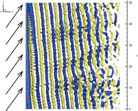
¼01 corresponds to the normal flow configuration; this definition is adopted in the present work based on the position of the flexible cylinder in quiescent fluid. The influence of the cylinder inclination on the flow has been well documented in the case of a stationary body (Van Atta, 1968; Ramberg, 1983;Lucor and Karniadakis, 2003; Thakur et al., 2004; Zhao et al., 2009; Willden and Guerbi, 2010). At large inclination angle, it was shown that the spanwise vortex rows forming downstream of the cylinder are not necessarily parallel to its axis. This phenomenon is illustrated inFig. 1for a stationary cylinder atα
¼601 and a Reynolds number (Re) equal to 500, based on the inflow velocity and cylinder diameter. Several studies have examined the possibility of likening the inclined body case to the normal incidence case through normalization of the physical quantities (e.g. vortex shedding frequency, fluid forces) by the component of the oncoming flow velocity perpendicular to the cylinder. This approach, referred to as cosine law or independence principle (IP), assumes that the flow dynamics is essentially driven by the inflow normal component and that the component aligned with the cylinder axis, the axial component, has a negligible impact. Although no consensus exists in the literature regarding the range of validity of the IP, due among others to the flow sensitivity to the cylinder end conditions, it was generally shown to provide accurate predictions of the flow physics forα
o401 approximately. Discrepancies may occur at larger inclination angles when the influence of the axial flow component becomes significant; this is the case in the configuration presented in Fig. 1, where the vortex shedding frequency normalized by the cylinder diameter and the inflow normal component is 13% larger than in the absence of axial flow (normal incidence). Such deviations were also reported byLucor and Karniadakis (2003),Thakur et al. (2004)andWillden and Guerbi (2010)for similar configurations.Ramberg (1983)emphasized the close connection between deviation from the IP and occurrence of oblique vortex shedding.
Compared to the stationary body case, a transverse oscillation of the cylinder tends to force parallel shedding (Ramberg, 1983;Lucor and Karniadakis, 2003;Willden and Guerbi, 2010); this suggests that the IP could be valid over a wider range of inclination angles for a flexibly mounted rigid cylinder subjected to VIV.Jain and Modarres-Sadeghi (2013)andFranzini et al. (2013)have reported that the IP can predict the onset of the lock-in regime as a function of the reduced velocity (i.e. inverse of the oscillator natural frequency normalized by the cylinder diameter and the inflow velocity), for
α
r651, and provide a qualitative estimation of the lock-in range up toα
¼551. They have also shown that the body inclination reduces the transverse response amplitude; hence, the application of the IP may lead to an overestimation of the rigid cylinder vibration amplitude. 0 10 20 30 40 50z
x y zFig. 1. Instantaneous iso-surfaces of the spanwise vorticity downstream of a stationnary cylinder inclined at 601 (ωzn¼ 70:6). Arrows represent the
VIV of long flexible structures immersed in normal currents have been the object of several works which have reported some similarities with the flexibly mounted rigid cylinder case but also highlighted the increased complexity of the mechanisms of interaction between the flow and the deformable body (Brika and Laneville, 1993;Trim et al., 2005;Chaplin et al., 2005;Huera-Huarte and Bearman, 2009a;Modarres-Sadeghi et al., 2011;Bourguet et al., 2011a,b). The influence of a sheared cross-current on the fluid–structure system behavior has been analyzed in the previous studies concerning flexible bodies (Lie and Kaasen, 2006;Vandiver et al., 2009;Lucor et al., 2006;Modarres-Sadeghi et al., 2010;Bourguet et al., 2012,
2013a) but the impact of the structure inclination remains to be investigated. The possible application of the IP to flexible body configurations also needs to be clarified with a special attention paid to the effect of the in-line curvature of the structure induced by the current.
With the aim of shedding light on the VIV of slender deformable bodies inclined in flow and assessing the validity of the IP, a joint analysis of the structural responses, wake patterns and fluid forces is reported in this paper for a flexible circular cylinder of length to diameter aspect ratio 50, placed at 601 of inclination in a flow at Reynolds number 500. The flexible cylinder is modeled as a tension-dominated structure; a high and a lower value of the tension, leading first to a small and then to a larger in-line bending, are considered. The analysis is based on direct numerical simulation results. The inclination angle
α
¼601 is selected because it is large enough to cause a deviation from the IP in the stationary body case but still allows VIV to appear, as shown in the previous studies concerning flexibly mounted rigid cylinders (e.g. Lucor and Karniadakis, 2003).The paper is organized as follows. The physical model and the numerical method are described inSection 2. The high-tension configuration is analyzed inSection 3. The lower-tension case is examined inSection 4. The main findings of this work are summarized inSection 5.
2. Fluid–structure model and numerical method
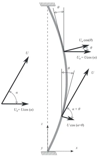
A sketch of the physical configuration is presented inFig. 2. The cylinder has a circular cross-section and a length (L) to diameter (D) aspect ratio L=D ¼ 50; it is pinned at both ends and free to oscillate in the in-line (x-axis) and cross-flow
x y z U Un= Ucos (α) α U U cos (α+θ) α + θ θ θ θ Un cos(θ) Un = Ucos (α)
Fig. 2. Sketch of the physical configuration. Plain black arrows represent the oncoming flow velocity components. The position of the cylinder in quiescent fluid is indicated by a dashed gray line.
(y-axis) directions. The cylinder is inclined at
α
¼601 within a uniform current of velocity magnitude U. The Reynolds number based on U and D, Re ¼ρ
fUD=μ
, whereρ
fandμ
denote the fluid density and viscosity, respectively, is set equal to500. The flow past the flexible cylinder is predicted using direct numerical simulation of the three-dimensional incompressible Navier–Stokes equations. Due to the current, the flexible cylinder tends to bend downstream; in the following, the axial and normal components of the oncoming flow are defined based on the position of the cylinder in quiescent fluid, similarly to the inclination angle
α
. The inflow axial component refers to the component parallel to the cylinder in a fluid at rest (z-axis) and the inflow normal component designates the component aligned with the x-axis. The velocity magnitude of the inflow normal component is Un¼ Ucos ðα
Þ. The local angle between the z-axis (position in quiescent fluid) and the cylinder axis in its time-averaged position in flow is denoted byθ
. The part of the total inflow velocity locally perpendicular to the cylinder is equal to U cos ðα
þθ
Þand the part of the inflow normal component (parallel to the x-axis) locally perpendicular to the body axis is equal to Un cos ðθ
Þ. For comparison purpose, a normal incidence case where the inflow axial component is removed is also considered; the Reynolds number is kept constant.All the physical variables are non-dimensionalized by
ρ
f, D and U. The cylinder mass ratio, defined as m ¼ρ
c=ρ
fD2, whereρ
cis the cylinder mass per unit length, is set to 6. The constant tension and damping of the structure are designated byτ
andη
, respectively. The non-dimensional tension is defined as T ¼τ
=ρ
fD2U2and the non-dimensional damping as K ¼η
=ρ
fDU. The non-dimensional displacements of the cylinder in the in-line and cross-flow directions are denoted byζ
x andζ
y, respectively. The sectional in-line and cross-flow force coefficients are defined as Cx¼2Fx=ρ
fDU2and Cy¼2Fy=ρ
fDU2, where Fxand Fyare the in-line and cross-flow dimensional sectional fluid forces, respectively. The structural dynamics aregoverned by forced vibrating string equations which can be expressed as follows in non-dimensional form (Lucor et al., 2006):
m €
ζ
fx;yg' Tζ
″fx;ygþ K _ζ
fx;yg¼ Cfx;yg2 ; ð1Þ
where _ and0denote the time and space derivatives, respectively. The string non-dimensional phase velocity is
ω
¼ ffiffiffiffiffiffiffiffiffiffi T=m p. Two values of T, 124 and 13.5, are considered; these values which lead respectively to a small and to a much larger in-line bending of the cylinder, allow to study the potential impact of this bending on the IP validity. The structural damping is set equal to zero (K¼0) to allow maximum amplitude oscillations.
The parallelized code Nektar, based on the spectral/hp element method (Karniadakis and Sherwin, 1999), is used to solve the coupled fluid–structure system. The version of the code employs a Jacobi–Galerkin formulation in the (x, y) plane and a Fourier expansion in the spanwise (z) direction. A boundary-fitted coordinate formulation is used to take into account the cylinder unsteady deformation. Details concerning the numerical method and its validation have been reported inNewman and Karniadakis (1997)andEvangelinos and Karniadakis (1999)for similar configurations. The computational domain (50D downstream and 20D in front, above, and below the cylinder) and discretization (2175 elements with polynomial order p¼7 in the (x; y) plane and 512 complex Fourier modes in the z direction) are the same as inBourguet et al. (2011a). The present analysis is based on time series of more than 300 time units, collected after convergence of the time-averaged in-line displacement of the cylinder.
3. High tension
The behavior of the fluid–structure system is examined in this section for a high value of the non-dimensional tension (T¼124). The IP validity is analyzed through comparison with the normal incidence case.
3.1. Structural vibrations
The flexible cylinder inclined at 601 exhibits regular vibrations, as illustrated inFig. 3(a) and (b) where selected time series of the in-line displacement fluctuation and cross-flow displacement are plotted along the span; in the in-line direction, the time-averaged displacement of the cylinder has been subtracted from the structural response. In this figure and in the following, the fluctuations are denoted by a tilde (~). Due to the high value of the tension, the time-averaged in-line displacement of the cylinder remains lower than 0.7D leading to a small static curvature of the structure. A larger in-in-line bending will be envisaged in Section 4. The cylinder vibrations are characterized by standing-wave patterns. A single frequency dominates the response spectrum in each direction as can be observed in the span-averaged power spectral densities (PSD) of the displacements presented inFig. 3(c) and (d). In these plots, the frequency is non-dimensionalized using the normal component of the inflow velocity (Un), for comparison purpose with the normal incidence case. In the
following, the physical quantities non-dimensionalized by Unare denoted by the subscript ð Þn. As generally observed in this context (e.g. Bourguet et al., 2011a), the in-line and cross-flow responses exhibit a frequency ratio of 2. The vibrations involve a single structural wavenumber in each direction; as suggested by the linear dispersion relation of a string in vacuum, the in-line and flow vibration wavenumbers also present a ratio of 2: 0.04 and 0.02 in the in-line and cross-flow directions, respectively. These low structural wavenumbers correspond to the fourth and second sine Fourier modes, with the nth mode defined as sin ð
π
nzD=LÞ. The following dispersion relation may be used to estimate the natural frequencyf associated with the structural wavenumber k when the cylinder is immersed in fluid: f ¼ k
ω
ffiffiffiffiffiffiffiffiffiffiffiffiffiffiffiffiffiffiffiffi m mþπ
4Cm v u u t ; ð2Þwhere Cmis the added mass coefficient induced by the fluid forces in phase with the cylinder acceleration. The natural
frequencies, normalized by Un, and associated with the in-line and cross-flow excited wavenumbers, for Cm¼1, are indicated
by dashed-dotted red lines inFig. 3(c) and (d). The actual peaks are close to the estimated natural frequencies. The spanwise evolutions of the root mean square (RMS) values of the displacements are presented inFig. 3(e) and (f). These plots confirm the standing-wave nature of the structural responses. The ratio between the maxima of the cross-flow and in-line displacement RMS values, equal to 3.5 approximately, is comparable to the ratios reported in the previous studies concerning low-wavenumber VIV of flexible cylinders at normal incidence (Huera-Huarte and Bearman, 2009a).
The PSD and RMS values of the flexible cylinder responses observed when the axial component of the inflow is removed (i.e. normal incidence case) are superimposed to the inclined case results inFig. 3(c)–(f). The vibrations occurring in the inclined and normal cylinder cases are almost identical in terms of spectral contents and oscillation amplitudes.
To further investigate the structural responses, the synchronization of the in-line and cross-flow vibrations is analyzed in the following. The phase difference between the in-line and cross-flow displacements determines the shape and orientation of the cylinder trajectories in the plane perpendicular to the span. The phase difference between responses occurring with a frequency ratio of 2 can be defined as
Φ
xy¼ ½ϕ
x'2ϕ
y; mod 3601*. The instantaneous phases of the in-line and cross-flow0 10 20 30 40 50 0 5 10 15 20 25 30 35 40 45 50 −0.2 −0.15 −0.1 −0.05 0 0.05 0.1 0.15 0.2 0.1 0.2 0.3 0.4 0.5 0.6 0 0.1 0.2 0.3 0.4 0.5 0.6 0.7 0.8 0.9 1 0 0.05 0.1 0.15 0 5 10 15 20 25 30 35 40 45 50 0 10 20 30 40 50 0 5 10 15 20 25 30 35 40 45 50 −0.6 −0.4 −0.2 0 0.2 0.4 0.6 0.05 0.1 0.15 0.2 0.25 0.3 0 0.1 0.2 0.3 0.4 0.5 0.6 0.7 0.8 0.9 1 0 0.1 0.2 0.3 0.4 0.5 0 5 10 15 20 25 30 35 40 45 50
Fig. 3.(a and b) Selected time series of the inclined cylinder displacement along the span, (c and d) span-averaged PSD of the displacement and (e and f) spanwise evolution of the displacement RMS value, in the (a, c and e) in-line and (b, d and f) cross-flow directions. In the in-line direction, the fluctuation of the cylinder displacement about its time-averaged value is considered. In (c and d), the natural frequency associated with the excited wavenumber is indicated by a dashed-dotted red line. (For interpretation of the references to color in this figure caption, the reader is referred to the web version of this article.)
responses (
ϕ
xandϕ
yrespectively) are determined by means of the Hilbert transform. Values ofΦ
xyin the range 01–1801(1801–3601 respectively) correspond to ‘figure eight’ orbits where the body moves upstream (downstream) when reaching the cross-flow oscillation maxima; these two types of trajectories are referred to as ‘counter-clockwise’ and ‘clockwise’, respectively (Dahl et al., 2007). For
Φ
xy¼01 andΦ
xy¼1801, the cylinder exhibits crescent-shaped orbits. The spanwise evolution of the histogram ofΦ
xyin the inclined body case is plotted inFig. 4(a). As shown in a previous work concerningflexible cylinders at normal incidence (Bourguet et al., 2013b), the standing-wave nature of the vibrations induces a discontinuous spanwise pattern of the phase difference. The structural responses are dominated by two synchronization states which correspond to trajectories close to crescent-shaped orbits; the two typical trajectories of the inclined cylinder are presented inFig. 4(b). As shown inFig. 4(c), the normal incidence case exhibits a very similar synchronization pattern along the span.
The above observations highlight the absence of significant effect of the axial flow component on the structural dynamics, in the present configuration. The next subsection focuses on the flow downstream of the vibrating cylinder. 3.2. Wake patterns
The frequency of vortex shedding is determined from the PSD of the cross-flow component of the flow velocity in the wake. In both the inclined and normal body cases, the vortex shedding frequency and the cross-flow oscillation frequency coincide at each point of the cylinder length: the lock-in condition is thus established along the entire span.
An overview of the wake patterns downstream of the freely oscillating flexible cylinder inclined in the current is presented inFig. 5(a) by means of instantaneous iso-surfaces of the spanwise vorticity; the vorticity is non-dimensionalized using Un. The wake is notably more disordered than in the stationary cylinder case, at the same inclination angle (Fig. 1).
As reported in the previous works (Lucor and Karniadakis, 2003;Willden and Guerbi, 2010) and also illustrated inFig. 1, the wake of the stationary cylinder exhibits a clear oblique vortex shedding pattern. In contrast, the spanwise vortex rows forming downstream of the vibrating flexible body appear to remain essentially parallel to the cylinder axis in the near wake. Such transition from oblique to parallel shedding under body oscillation was also noted in the above-mentioned studies, for rigid cylinders at similar inclination angles.
A visualization of the wake patterns in the normal incidence case is presented inFig. 5(b); for comparison purpose, the same levels of spanwise vorticity as in the inclined body case are selected to plot the instantaneous iso-surfaces. The wake patterns are analogous to those observed downstream of the inclined cylinder and no substantial influence of the axial flow component is revealed by these visualizations. The fluid forces acting on the oscillating body are addressed in the following. 3.3. Fluid forces
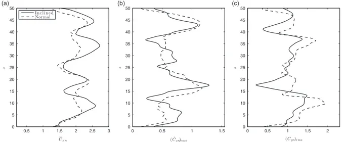
The spanwise evolutions of the time-averaged (designated by an overline ( )) in-line force coefficient and of the RMS values of the in-line and cross-flow force coefficients are plotted inFig. 6, for the inclined and normal body cases. In these plots, the fluid forces are non-dimensionalized by Un. As also reported in the previous studies concerning rigid and flexible
cylinders in normal flow (e.g.Khalak and Williamson, 1999;Huera-Huarte and Bearman, 2009b), the body oscillations are
Fig. 4.(a) Histogram of phase difference between the in-line and cross-flow displacements along the span in the inclined cylinder case. (b) Typical trajectories of the inclined cylinder. (c) Same as (a) in the normal cylinder case. In (a and c), the limit between counter-clockwise and clockwise orbits (Φxy¼1801) is indicated by a vertical dashed line.
accompanied by an amplification of the time-averaged in-line force coefficient and of the force coefficient fluctuations; the span-averaged value of Cxnis equal to 2.1 and 2 in the inclined and normal vibrating cylinder cases, respectively, versus 1.35 and 1.15 in the inclined and normal stationary body cases. In spite of some differences, as for instance in the peak RMS values of Cyn which are larger at normal incidence, the inclined and normal body cases globally exhibit close spanwise
trends of the force coefficients, with comparable magnitudes.
The effective in-line and cross-flow added mass coefficients due to the fluid forces in phase with the body acceleration are determined as follows:
Cmx¼ '2
π
Cxζ
€x €ζ
2x ; Cmy¼ '2π
Cyζ
€y €ζ
2y : ð3ÞAs can be observed inFig. 7, Cmxand Cmypresent large spanwise modulations with similar behaviors in the inclined and
normal cylinder cases. It appears that the variability of the effective added mass coefficients and their departure from the
0 10 20 30 40 50 z x y z
Fig. 5.Instantaneous iso-surfaces of the spanwise vorticity downstream of the (a) inclined and (b) normal flexible cylinders (ωzn¼ 70:8). Arrows
represent the oncoming flow. Part of the computational domain is shown.
Fig. 6.(a) Time-averaged value of the in-line force coefficient, (b) RMS value of the in-line force coefficient fluctuation and (c) RMS value of the cross-flow force coefficient, along the span.
potential flow value of 1, do not induce significant differences between the excited frequencies and the natural frequencies determined through the dispersion relation(2). A trend can be noted in the evolution of Cmy, in relation with the shape of
the cylinder trajectory: values close to 1 are reached in the regions of the span dominated by crescent-shaped orbits bent downstream, while much smaller, and even negative values of Cmyare observed in zones associated with crescent-shaped
orbits bent upstream. Previous works have highlighted close connections between the orbit shape/orientation and the fluid forcing (Dahl et al., 2007;Bourguet et al., 2011b,2013a). The link observed between the value of the effective added mass coefficient and the trajectory shape may be attributed to the specific distance between the cylinder and the recently shed vortices for each type of orbit; a closer proximity when the orbit is bent upstream may result in a stronger interaction between the body and the vortices, and especially in a larger influence of the vortex suction forces, which could explain the substantial deviation of Cmyfrom the potential flow value. No clear trend can be identified in the in-line direction.
The analysis reported in this section shows that the fluid–structure system exhibits a similar behavior in the inclined and normal body cases, as long as the inflow normal component is used to normalize the physical quantities. The IP is thus valid in the present configuration and it can be used to predict accurately the structural responses and fluid forces in the inclined body case, based on the normal incidence case results. The question arises whether this conclusion can be extended to lower-tension configurations characterized by a larger in-line bending; this question is investigated in the next section. 4. Lower tension
The behavior of the coupled fluid–structure system is studied in this section for a lower value of the non-dimensional tension (T¼13.5). The objective here is not to repeat the extensive analysis presented for a high-tension case inSection 3but to assess the validity range of the IP and pinpoint some possible limitations related to the flexible nature of the structure. 4.1. Fluid–structure system behavior
Under lower tension, the inclined flexible cylinder still exhibits regular in-line and cross-flow VIV. However, contrary to the high-tension configuration, the structural responses observed in the inclined cylinder case substantially deviate from those noted in the normal body case. It is recalled that the axial component of the inflow velocity, which is removed in the normal body case, refers to the component aligned with the cylinder axis in quiescent fluid, and the remaining normal component (Un) is parallel to the x-axis; the influence of the inflow component locally perpendicular to the cylinder once it
bends in the current will be examined in the next subsection. The differences in the structural vibrations, between the inclined and normal cylinders, are illustrated inFig. 8(a), which represents the spanwise evolution of the RMS value of the cross-flow displacement, for both cases. As expected from the dispersion relation(2), due to the reduction of the tension, the vibrations involve higher structural wavenumbers than in the previous configuration. In the present lower-tension configuration, the inclined cylinder exhibits globally smaller amplitudes of vibration than the normal one; the span-averaged value of the RMS cross-flow displacement is equal to 0.29 in the inclined case versus 0.35 in the normal case, and the peak RMS values along the span differ by more than 45%. As shown inFig. 8(b), the predominant vibration frequencies, normalized by Un, are comparable in the inclined and normal cylinder cases, and remain close to the natural frequency
estimated through the dispersion relation(2). A difference can however be noted in the response spectral contents: in the inclined cylinder case, the vibration spectrum exhibits two secondary contributions, which do not exist in the normal body
Fig. 7.Effective added mass coefficient in the (a) in-line and (b) cross-flow directions, along the span. The potential flow value of 1 is indicated by a dashed-dotted red line.
case. As a result, despite the moderate magnitudes of these secondary spectral contributions, the structural response of the inclined cylinder appears to be multi-frequency whereas the vibration remains mono-frequency in the normal incidence case. The fluid force coefficients, normalized by Un, also present significant differences in the inclined and normal body
cases, as shown inFig. 8(c) where the RMS value of Cynis plotted along the span. The above analysis focuses on the system
behavior in the cross-flow direction but similar observations can be made in the in-line direction.
As a consequence, for the present lower-tension configuration, the behavior of the fluid–structure system in the inclined cylinder case cannot be predicted on the basis of the normal incidence case results. Application of the IP would lead, among others, to an overestimation of the vibration amplitudes and would not predict the multi-frequency nature of the responses. This contrasts with the previous conclusion concerning the validity of the IP in the high-tension configuration. In the following, the limitations of the IP are studied in light of the larger in-line bending of the cylinder, due to the lower tension. 4.2. Influence of the cylinder in-line bending
The time-averaged in-line displacement of the cylinder is plotted along the span inFig. 9(a), for the inclined and normal cylinder cases. The in-line bending slightly differs between the two cases; the body inclination induces an asymmetric curvature of the cylinder. The part of the inflow velocity normal component (parallel to the x-axis) that is locally perpendicular to the cylinder axis (Un cos ð
θ
Þ) is plotted inFig. 9(b), for both cases. In this plot and in the following, the velocity profiles are non-dimensionalized by U. The difference in the in-line bending causes a slight modification of the locally perpendicular velocity profile between the two cases. Previous works have shown that moderate changes in the velocity profile may considerably impact the system behavior, and for instance cause transition from mono-frequency to multi-frequency responses (e.g.Bourguet et al., 2012). In order to quantify the effect of the profile modification, the inflow velocity in the normal incidence case is altered so that the velocity locally perpendicular to the cylinder matches the profile of Un cos ðθ
Þin the inclined body case; the new inflow velocity profile is referred to as profile A. The Fourier expansion used in the z direction implies spanwise periodicity of the inflow velocity profile; this constraint is taken into account in the design of the new profile. The resulting profile of velocity locally normal to the cylinder is plotted inFig. 9(b) (dotted line); it is very close to the profile observed in the inclined body case. As can be noted inFig. 8, where the results obtained for the velocity profile A are plotted in dotted lines, the behavior of the system is not significantly modified by this new inflow velocity profile, compared to the uniform profile case (dashed lines). As a consequence, it appears that the modification of the locally perpendicular part of Undue to the alteration of the in-line bending has a very limited influence on the systemresponses and does not explain the differences noted between the inclined and normal body cases.
Because of the cylinder time-averaged in-line displacement, part of the inflow axial component (parallel to the z-axis) is locally perpendicular to the cylinder axis. As shown inFig. 9(c), the profile of the total inflow velocity locally perpendicular to the cylinder (U cos ð
α
þθ
Þ) in the inclined cylinder case considerably differs from the normal body case profile (dashed line inFig. 9(b)). The body in-line bending results in a large shear of the locally perpendicular velocity profile along the span in the inclined cylinder case, whereas the profile remains close to uniform in the normal incidence case; such shear may be responsible for the occurrence of multi-frequency vibrations in the former case. To clarify this point, the inflow velocity in the normal incidence case is modified in order to emulate the locally perpendicular velocity observed in the inclined cylinder case. The new inflow profile, referred to as profile B, leads to the locally normal velocity profile represented by a dashed-dotted line inFig. 9(c); it matches the inclined body profile, except near the ends due to the spanwise periodicityFig. 8. (a) Spanwise evolution of the RMS value of the cross-flow displacement. (b) Span-averaged PSD of the cross-flow displacement; the natural frequency associated with the predominant excited wavenumber is indicated by a dashed-dotted red line. (c) Spanwise evolution of the RMS value of the cross-flow force coefficient.
condition. When exposed to the inflow profile B, the cylinder exhibits multi-frequency structural vibrations comparable to those noted in the inclined body case, as can be observed inFig. 8(a) and (b) (dashed-dotted lines). The fluid forces also tend to be closer to those noted in the inclined cylinder case (Fig. 8(c)). The small discrepancies observed in the system responses between the two cases may be attributed to the differences in the locally normal velocity near the cylinder ends (Fig. 9(c)) and to the effect of the flow locally parallel to the body, which differs in both cases. However, the global proximity of the responses in the inclined and normal body cases under analogous locally perpendicular velocity profiles indicates that the system behavior is mainly determined by this component of the inflow. Hence, the differences highlighted inSection 4.1
between the inclined and normal body cases in uniform current, especially the transition from mono-frequency to multi-frequency vibrations, appear as a consequence of the cylinder in-line bending which causes a substantial alteration of the locally perpendicular velocity component.
The central role of the locally perpendicular velocity and the limited impact of the flow locally parallel to the body could be regarded as a local extension of the IP. Nonetheless, such local extension cannot be used to predict the behavior of the inclined body from the normal incidence case results in uniform current; among other reasons because this approach requires an a priori knowledge of the in-line bending in the inclined case and because the scaling of the normal case vibration frequencies using the variable, locally perpendicular flow velocity leads to continuous spectra which do not allow to identify which frequencies will emerge in the inclined cylinder responses.
When the standard definition of the IP is applied, i.e. matching the inclined and normal case responses in the same current through normalization by Un, the contribution of the inflow axial component locally perpendicular to the bent
cylinder is ignored. However, this part of the inflow may modify the shape of the total current locally perpendicular to the body and thus directly impact the system responses. Therefore, the IP which was shown to be valid inSection 3for a configuration where the in-line time-averaged displacement was small can fail once the in-line bending of the cylinder becomes significant, as reported in the present section.
5. Conclusions
The vortex-induced vibrations of a flexible cylinder inclined at 601 have been investigated by means of direct numerical simulation, at a Reynolds number equal to 500. In order to examine the validity of the IP in this context, a normal incidence case where the inflow component aligned with the cylinder axis in quiescent fluid (axial component) was removed was also considered. The cylinder was modeled as a tension-dominated structure and two values of the non-dimensional tension were selected to study the possible influence of the cylinder time-averaged in-line bending on the IP validity.
For both values of the non-dimensional tension, the inclined cylinder exhibits regular VIV in the in-line and cross-flow directions. In the high-tension configuration, where the in-line bending of the cylinder remains small, a joint analysis of the cylinder vibrations, wake patterns and fluid forces shows that the IP is valid: the coupled fluid–structure system exhibits similar behaviors in the inclined and normal body cases, once Un, the inflow component normal to the cylinder axis in
quiescent fluid, is used to normalize the physical quantities. In this configuration, the IP can thus be applied to predict the structural responses and the forces exerted by the flow in the inclined body case, based on the normal incidence case results. In contrast, in the lower-tension configuration, the behavior of the fluid–structure system clearly deviates from the IP: the physical quantities in the inclined and normal body cases do not match after normalization by Un. Additional simulations
Fig. 9. (a) Spanwise evolution of the time-averaged in-line displacement. (b) Part of the inflow velocity normal component locally perpendicular to the cylinder and (c) part of the total inflow velocity locally perpendicular to the cylinder, along the span. In (b and c), the velocity profiles are non-dimensionalized by U.
performed with modified inflow velocity profiles indicate that the system behavior is principally driven by the flow velocity locally normal to the cylinder. Due to the larger in-line bending of the structure, induced by the lower tension, a significant part of the inflow axial component is locally perpendicular to the cylinder; the total inflow locally perpendicular to the body thus considerably differs between the inclined and normal body cases, resulting in distinct responses of the fluid–structure system. The large shear of the locally perpendicular velocity profile in the inclined cylinder case causes multi-frequency vibrations whereas the normal incidence case, for which the profile is almost uniform, is characterized by mono-frequency oscillations. Application of the IP to predict the system responses in the inclined cylinder case would lead to an overestimation of the vibration amplitudes and would not capture the transition from mono-frequency to multi-frequency responses. These results show that the validity of the IP may be substantially impacted by the in-line bending of the flexible structure.
Acknowledgments
The authors wish to acknowledge support from the BP-MIT Major Projects Programme, monitored by M. Tognarelli and P. Beynet; and the Office of Naval Research under Grants N00014-07-1-0135 and N00014-07-1-0446, monitored by T. Swean, Jr.
References
Bearman, P.W., 1984. Vortex shedding from oscillating bluff bodies. Annual Review of Fluid Mechanics 16, 195–222.
Bearman, P.W., 2011. Circular cylinder wakes and vortex-induced vibrations. Journal of Fluids and Structures 27, 648–658.
Bishop, R.E.D., Hassan, A.Y., 1964. The lift and drag forces on a circular cylinder oscillating in a flowing fluid. Proceedings of the Royal Society of London Series A: Mathematical and Physical Sciences 277, 51–75.
Bourguet, R., Karniadakis, G.E., Triantafyllou, M.S., 2013a. Distributed lock-in drives broadband vortex-induced vibrations of a long flexible cylinder in shear flow. Journal of Fluid Mechanics 717, 361–375.
Bourguet, R., Karniadakis, G.E., Triantafyllou, M.S., 2013b. Phasing mechanisms between the in-line and cross-flow vortex-induced vibrations of a long tensioned beam in shear flow. Computers and Structures 122, 155–163.
Bourguet, R., Lucor, D., Triantafyllou, M.S., 2012. Mono- and multi-frequency vortex-induced vibrations of a long tensioned beam in shear flow. Journal of Fluids and Structures 32, 52–64.
Bourguet, R., Karniadakis, G.E., Triantafyllou, M.S., 2011a. Vortex-induced vibrations of a long flexible cylinder in shear flow. Journal of Fluid Mechanics 677, 342–382.
Bourguet, R., Modarres-Sadeghi, Y., Karniadakis, G.E., Triantafyllou, M.S., 2011b. Wake-body resonance of long flexible structures is dominated by counter-clockwise orbits. Physical Review Letters 107, 134502.
Brika, D., Laneville, A., 1993. Vortex-induced vibrations of a long flexible circular cylinder. Journal of Fluid Mechanics 250, 481–508.
Carberry, J., Sheridan, J., Rockwell, D., 2001. Forces and wake modes of an oscillating cylinder. Journal of Fluids and Structures 15, 523–532.
Chaplin, J.R., Bearman, P.W., Huera-Huarte, F.J., Pattenden, R.J., 2005. Laboratory measurements of vortex-induced vibrations of a vertical tension riser in a stepped current. Journal of Fluids and Structures 21, 3–24.
Dahl, J.M., Hover, F.S., Triantafyllou, M.S., Dong, S., Karniadakis, G.E., 2007. Resonant vibrations of bluff bodies cause multivortex shedding and high frequency forces. Physical Review Letters 99, 144503.
Dahl, J.M., Hover, F.S., Triantafyllou, M.S., Oakley, O.H., 2010. Dual resonance in vortex-induced vibrations at subcritical and supercritical Reynolds numbers. Journal of Fluid Mechanics 643, 395–424.
Evangelinos, C., Karniadakis, G.E., 1999. Dynamics and flow structures in the turbulent wake of rigid and flexible cylinders subject to vortex-induced vibrations. Journal of Fluid Mechanics 400, 91–124.
Franzini, G.R., Fujarra, A.L.C., Meneghini, J.R., Korkischko, I., Franciss, R., 2009. Experimental investigation of vortex-induced vibration on rigid, smooth and inclined cylinders. Journal of Fluids and Structures 25, 742–750.
Franzini, G.R., Gonçalves, R.T., Meneghini, J.R., Fujarra, A.L.C., 2013. One and two degrees-of-freedom vortex-induced vibration experiments with yawed cylinders. Journal of Fluids and Structures 42, 401–420.
Huera-Huarte, F.J., Bearman, P.W., 2009a. Wake structures and vortex-induced vibrations of a long flexible cylinder. Part I. Dynamic response. Journal of Fluids and Structures 25, 969–990.
Huera-Huarte, F.J., Bearman, P.W., 2009b. Wake structures and vortex-induced vibrations of a long flexible cylinder. Part II. Drag coefficients and vortex modes. Journal of Fluids and Structures 25, 991–1006.
Jain, A., Modarres-Sadeghi, Y., 2013. Vortex-induced vibrations of a flexibly mounted inclined cylinder. Journal of Fluids and Structures 43, 28–40.
Jeon, D., Gharib, M., 2001. On circular cylinders undergoing two-degree-of-freedom forced motions. Journal of Fluids and Structures 15, 533–541.
Karniadakis, G.E., Sherwin, S., 1999. Spectral/hp Element Methods for CFD, first ed. Oxford University Press, Oxford.
Khalak, A., Williamson, C.H.K., 1999. Motions, forces and mode transitions in vortex-induced vibrations at low mass-damping. Journal of Fluids and Structures 13, 813–851.
King, S., 1977. Vortex excited oscillations of yawed circular cylinders. Journal of Fluids Engineering 99, 495–502.
Lie, H., Kaasen, K.E., 2006. Modal analysis of measurements from a large-scale VIV model test of a riser in linearly sheared flow. Journal of Fluids and Structures 22, 557–575.
Lucor, D., Karniadakis, G.E., 2003. Effects of oblique inflow in vortex-induced vibrations. Flow, Turbulence and Combustion 71, 375–389.
Lucor, D., Mukundan, H., Triantafyllou, M.S., 2006. Riser modal identification in CFD and full-scale experiments. Journal of Fluids and Structures 22, 905–917.
Mittal, S., Tezduyar, T.E., 1992. A finite element study of incompressible flows past oscillating cylinders and aerofoils. International Journal for Numerical Methods in Fluids 15, 1073–1118.
Modarres-Sadeghi, Y., Chasparis, F., Triantafyllou, M.S., Tognarelli, M., Beynet, P., 2011. Chaotic response is a generic feature of vortex-induced vibrations of flexible risers. Journal of Sound and Vibration 330, 2565–2579.
Modarres-Sadeghi, Y., Mukundan, H., Dahl, J.M., Hover, F.S., Triantafyllou, M.S., 2010. The effect of higher harmonic forces on fatigue life of marine risers. Journal of Sound and Vibration 329, 43–55.
Newman, D.J., Karniadakis, G.E., 1997. A direct numerical simulation study of flow past a freely vibrating cable. Journal of Fluid Mechanics 344, 95–136.
Ramberg, S.E., 1983. The effects of yaw and finite length upon the vortex wakes of stationary and vibrating circular cylinders. Journal of Fluid Mechanics 128, 81–107.
Sarpkaya, T., 2004. A critical review of the intrinsic nature of vortex-induced vibrations. Journal of Fluids and Structures 19, 389–447.
Trim, A.D., Braaten, H., Lie, H., Tognarelli, M.A., 2005. Experimental investigation of vortex-induced vibration of long marine risers. Journal of Fluids and Structures 21, 335–361.
Van Atta, C.W., 1968. Experiments on vortex shedding from yawed circular cylinders. AIAA Journal 6, 931–933.
Vandiver, J.K., Jaiswal, V., Jhingran, V., 2009. Insights on vortex-induced, traveling waves on long risers. Journal of Fluids and Structures 25, 641–653. Willden, R.H.J., Guerbi, M., 2010. Vortex dynamics of stationary and oscillating cylinders in yawed flow. In: IUTAM Symposium on Bluff Body Wakes and
Vortex-Induced Vibrations (BBVIV-6), Capri, Italy, pp. 47–54.
Williamson, C.H.K., Govardhan, R., 2004. Vortex-induced vibrations. Annual Review of Fluid Mechanics 36, 413–455.
Zhao, M., Cheng, L., Zhou, T., 2009. Direct numerical simulation of three-dimensional flow past a yawed circular cylinder of infinite length. Journal of Fluids and Structures 25, 831–847.