JUN 23 1963)5
BRILLOUIN SCATTERING AND COHERENT PHONON GENERATION
by
Raymond Chiao
B. A.- Princetonr University (1961)
submitted in partial fulfillment of the requirements for the degree of
doctor of philosophy
at the
MASSACHUSETTS INSTITUTE OF TECHNOLOGY
June, 1965
Signature Redacted
Signature of Author. .i.n.u.
Redacted
Department of Physics, May 27, 1965 C ertified by . . . .
Themirnj qnerior
Accepted by...Signature
Redacted
Chairman, Departmental Committee ^g
u
R
te Students'Signature Redacted
-2-BRILLOUIN SCATTERING AND COHERENT PHONON GENERATION by
Raymond Chiao
Submitted to the Department of Physics on May 26, 1965 in partial fulfillment of the requirement for the
degree of doctor of philosophy
ABSTRACT
The scattering of light off sound waves, known as the (normal)Brillouin effect, has been previously used to investigate velocities of sound in the hypersonic range. Using a He-Ne red laser as the exciting source, one can improve such
measure-ments easily by better than an order of magnitude in accuracy. More importantly, this technique has allowed us to detect for the first time a significant width to the Brillouin components in some liquids, allowing us to measure the attenuation of hyper-sonic waves.
With the advent of extremely high-power lasers it is now possible to generate hypersonic waves of great intensity from light waves, using the stimulated Brillouin effect. One can view this effect as the parametric generation of sound from intense light in a nonlinear (e. g. electrostrictive) medium. The sound waves so generated are, in solids, typically in the frequency range of 20 KMc and have a peak power of-lKwatt of a duration
of ^- 3 x 10⁻⁸ sec.
A theoretical study has also been made on the possibility of diffractionless propagation of light beams which undergo non-linear (e. g. electrostrictive) interaction with the medium. Such a phenomenon may occur when the diffracted rays from a finite-aperture beam are confined by total internal reflection inside a dielectric waveguide which the light beam creates for itself.
Thesis Supervisor: Charles H. Townes
Title: Provost of M. I. T. and Professor of Physics
DEDICATION
I dedicate this thesis to my Saviour Jesus Christ, whose I am and whom I serve.
-4-ACKNOWLEDGEMENTS
I am deeply grateful to my thesis advisor, Professor Charles H. Townes, for the wealth of ideas which are the basis of this thesis. I wish to thank Professor Boris Stoicheff for invaluable experimental help. Professors Ali Javan and Jacques Ducuing and Uno Ingard gave me much us-eful advice, for
which I am grateful. I thank Professor Robert Newnham for X-ray identification of the axes of various crystals.
My thanks are especially extended to Elsa Garmire and Paul Fleury for collaboration in experiments and helpful
dis-cussions. To Dr. Abraham Szoke, Dr. Francesco DeMartini, Dr. George Flynn, Joel Parks, Ronald Cordover, Michael Feld, Howard Schlossberg, Lon Hocker, Mark Kovacs, John Murray, Richard Smith, Eugene Leonard, Richard Solomon and Eugene Pfitzer, I am grateful for illuminating discussions and for the loan of equipment.
Especial thanks are due to Mrs. Wanda Schwartz for typing my thesis.
I respectfully thank my parents for the many years of upbringing and encouragement they have given me.
BIOGRAPHICAL NOTE
The author was born in Hong Kong on October 9, 1940, and emigrated to America in 1947. He received an A. B. degree in physics from Princeton University in 1961 and is a member of Phi Beta Kappa (1960). His publications include "Angular
Depen-dence of Maser-Stimulated Raman Radiation in Calcite" (Phys. Rev. Letters, 12 290, 1964); "Stimulated Brillouin Scattering and
Coherent Generation of Intense Hypersonic Waves"(Phys. Rev. Letters, 12, 392, 1964); "Self-Trapping of Optical Beams" y Rev. Letters, 13, 1479, 1964); "Brillouin Scattering in Liquids Excited by the He-Ne Maser" (J. Opt. Soc. Am., 54, 1286, 1964);
"Raman and Phonon Masers" (Quantum Electronics and Coherent Light, Proc. of the International School of Physics "Enrico
Fermi", 1963, P. Miles and C. H. Townes, eds. , Academic Press, 1964, p. 326).
-6-TABLE OF CONTENTS
Page Introduction. . . . . 9 Chapter I. The Kinematics of Brillouin Scattering. . . . . . 10 Chapter II. The Dynamics of Brillouin Scattering . . . . 16 Chapter III. The Coupled Wave Equations and Their 25
Solutions . . . . Chapter IV. Experimental Observations of the Stimu- 51
lated Brillouin Effect . . . . Chapter V. Normal Brillouin Scattering . . . 75 Chapter VI. The Self-Trapping of Optical Beams . . . .114 Footnotes . . . 129
TABLE OF FIGURES
Page
Chapter I
1. Classical Description of Brillouin Scattering 10 2. Quantum Description of Brillouin Scattering 11 Chapter II
3. Condenser Immersed in a Fluid 16
4. Delay-line Immersed in a Fluid 17
Chapter III
5. Boundary Conditions for Backward Wave Amplifier 36
6. Graphical Solution for D 40
7. The Fourier Transform of the Field in the Focal 45 Region c (k) and its Self-Convolution c * c (k)
Chapter IV
8. Experimental Arrangement for Observing Stimu- 52 lated Brillouin Effect inside Cavity of Laser
9. Experimental Arrangement used by Takuma and 54 Jennings
10. Schematic of Experimental Apparatus used to 57 Observe Stimulated Brillouin Scattering in the
Backward Direction
11. Comparison of Fabry-Perot Interferograms of 59 Laser and Stimulated Brillouin Effect
12. Stimulated Brillouin Spectra of Solids Taken with 63 Fabry-Perot B
13. Simplified Apparatus for Detection of Stimulated 67 Brillouin Scattering
14. Experimental Arrangement used by Garmire and 69 Townes for Observation of Stimulated Brillouin
-8-TABLE OF FIGURES (con'd.)
Page
15. Stimulated Brillouin Spectra of Liquids 71 Chapter V
16. Normal Brillouin Scattering Diffracting from 76 Rectangular Paralpiped Target
ele
17. Radiation from an Extended Source 80
18. Experimental Arrangement used by Chiao and 88 Stoicheff for Observations of Normal Brillouin
Scattering in Liquids at 9 _=900
19. Recorder Traces of Brillouin Spectra Taken 91 with Experimental Arrangement as shown in
Fig. 18
20. Dispersion of Lossless Sound Waves near 95
Resonance
21. Experimental Arrangement for Observing Normal 98 Brillouin Scattering as a Function of Angle
22. Interferograms of Brillouin Scattering 100
23. The Dispersion and Absorption of Sound Waves 103 at Hypersonic Frequencies in Toluene
24. Exact Backward-Scattering Experiment 105
25. Brillouin Components Observed Using the Exact 107 Backward-Scattering Method
26. Experiments for Generation and Detection of 110 Acoustical and Raman Phonons
Chapter VI
27. Critical Reflection and Self-Trapping 116
28. Potential for Mechanical Analogue to Self-Trapping 118 29. Calculated Radial Distribution of Electric Field in 124
a Self-Trapped Electromagnetic Beam of Circular Cross-Section
Introduction
Radiation and matter can interact in a variety of ways. The lowest order process of interaction results in the familiar- one-photon absorption and the associated dispersion of electromagnetic radiation. This process is linear because the polarization of the matter responsible for these effects is linear in electric field. One consequence of this linearity is that there is no alteration (except for transient effects) of the frequency of the interacting radiation. Stimulated emission associated with this lowest order process has led to the now familiar maser and laser action.
The next order process of interaction results in
two-photon effects, such as the Raman and Brillouin scattering. These processes are nonlinear in the sense that the polarization of the
matter varies nonlinearly with the electric field. Thus new fre-quencies can arise through nonlinear mixing and parametric pro-cesses. For example, in Brillouin scattering in which light is
scattered off sound waves, the scattered light waves are shifted in frequency with respect to that of the incident light due to modulation by the scattering sound waves. As in the one-photon case, there are stimulated processes of emission and absorption associated
with two-photon effects in addition to the normal effects (i. e. scatter-ing from zer o-point and thermal fluctuations). These lead to the stimulated Brillouin effect and phonon maser action.
In this thesis, nonlinear interactions of light and the collec-tive motions of matter, in particular sound waves, will be investi-gated.
-10-Chapter I. The Kinematics of Brillouin Scattering
One may view Brillouin scattering either classically or quantum mechanically, but both give the same answer as far as the kinematics of the process is concerned. First, classically one envisages light waves being diffracted by a grating of periodically varying index of refraction
caused by the sound wave. The diffracted light will also suffer a Doppler shift since the grating is moving at the speed of sound. The Bragg law gives us (see fig. 1):
fig. 1: Classical Description of Brillouin Scattering
(1. 1) 2d cos = m m = 1, 2, 3, . . .
p
where f is the incidence angle and X is the incident wavelength and n is
p p
the index of refraction of the medium at X p. Since 9= -2 #0
2d sin- = P m
2 n
p
where 9 is the scattering angle. Since d = Xs, the wavelength of sound, and
=v 5 :
(1. 2) in)) - 2 n 1
sin-s CS p p2
The Doppler shift suffered by the scattered light is (as is easily seen by transforming into an inertial frame moving along with the sound wave):
(1. 3) = 2 n P( )cosp = n p() sin p
where 46)) is the Doppler shift. Since the sound wave is modulating the incident light at frequency 1/, we require ) = ) and hence m = 1 and
we obtain the Brillouin shift formula1 :
V
(1.4) 2
)/= 2n --
sin-s p p c
Of course, it must be pointed out that in the above analysis one makes the approximations that since v 10-5 the Doppler shift is small (and hence
c
first order) and the wavelength of the shifted radiation is very nearly equal to the incident wavelength, thus allowing us to use (1. 1).
Quantum mechanically, one envisages Brillouin scattering as a collision process in which a photon collides inelastically with a phonon and emerges as a photon of a different energy (see fig. 2).
(a) (b)
fig. 2: Quantum Description of Brillouin Scattering
Energy and momentum must be conserved in such a process, and since
TWi s represent the energies andti s represent the momenta of
-12-(1. 5) WJCJ= w
(s
i .021 + p s+ "anti-Stokes" I *h + + -"Stokes" (1.6) k = kp - kwhere + is for the case of phonon annihilation and - is for phonon creation. Now the magnitude of the wave-vectors are related to frequencies by:
(1. 7) k= n ki 1 n. , k = s
p c p 'i c s vs
It is clear that conservation of momentum, represented by the wave-vector triangle in fig. 2(b), implies the
Ik
, k i1,1k
) must be of the same order of magnitude so long as 9 is not small. Hence (1. 7) implies thatso() p is very small compared with
w. Thus from (1. 5) . - p
5
to a part in 10 and we may therefore also set n. n , whence:
1p
(1. 8) k p ki
implying that the triangle in fig. 2(b) is isosceles. Hence the sound wave always moves away from the scattered light wave (i. e. k .ks< 0). By geometry:
(1.9)
f
ks = 2 kI sinor, converting to frequencies using (1. 7)
(1. 10) s = 2np ( sin
which is identical to (1. 4). Again it must be pointed out that this relation-ship was derived with the assumption that v is small.
v
Let us investigate the case involving higher orders of - so that relativistic effects will become significant. We will start with equations (1. 5) and (1. 6). (Clasically, the interpretation of these equations, as will
become evident in the next chapter, is that of phase matching in time and space of the interacting waves.) The law of cosines applied to the wave-vector triangle (fig. 2(b)) gives us:
(1. 11) k = k. + k - 2k. k cos 9.
s 1 p i p
We assume n = np temporarily. This is not a good assumption since it is typically in error by a part in 10 so that it must be taken into account in first order correction to the Brillouin shift. Nevertheless, for algebraic
simplicity, we defer the discussion for the case n. # n Equations (1. 11)
1 p v
and (1. 5) imply the quadratic equation for ws (n. = n n,
p.M-
):s p c
2 2 2 2 2 s2 9 2 2 2. 2 9
(1. 12) Ws (1- n p) 4n
p
sin W 4nP
W sin 0which has the solutions:
(1.13) s np2 P2 2 n P sin2 + 4sin2 n22 sin2
where + is for the sound wave associated with the anti-Stokes (up-shifted in frequency, cf. (1. 5)) component of scattered radiation and - for the Stokes (down-shifted in frequency) component. We have chosen the + sign in front of the square root since in the limit P-00, ws must be positive. Expanding in orders of
P:
nP . 9 + 2 9 2 2 .9 2 9 4
(1.14) s 2 2 ( sin - - 2nP sin .- n p sin - cos 0 +O(p)+. ..
s -n 2P22
Thus both the Stokes and the anti-Stokes are shifted to the blue slightly,
v 2
-14-In the case when n . np the situation is complicated by the fact that (1. 12) is no longer quadratic and becomes:
2 22 2 2
(1. 15) W (1 2 -n~ i232 )PW (21 2 W (n.i - n n pcos 9))
S n.2 + n p) 2n. n pos 12 p 2 = 0
2
where n = n(Wp I WS) n np w sn + + d . .
We will solve (1. 15) neglecting terms O(P 4) and using ws = 0 (P). Then:
9 22 . 29 W d
(1.216) n
=2nfrA sin 2 n wsin 2(1+) + O(P3
p p * 2 p p n ~p + )
Therefore, the net shift to the blue of both Brillouin components described above is enhanced in the case of normal dispersion
(
0). For the caseof fused quartz -= 1. 3 x 10-p
We may also apply (1. 15) to the case of anisotropic crystals if we let n , . be the index of refraction along the incident and scattered directions respectively, with proper considerations of polarizations (same as from a dielectric boundary). Thus, neglecting dispersion:
2 (1.17) 2 (n 2 - n.n cos 9) 1-n
3P
2 2 2 1 2 2 nnp sin + ((n. +n )-2nn n cos 9) or to lowest orders3 .Ws = p(9)o (n + n 2) - 2n n cos 9 p2 (9) (n 2
+ 0 (p3)
where
P
is in general a function of 9, being dependent also on crystal orientation, and is computed from a secular equation 4 :(1. 19)
x iklm kkk 1 - 2 i 0
whe ref is the density, x iklm are the adiabatic moduli of elasticity. phase velocity along a propagation vector k is defined as V = where
ik w is an eigenfrequency of (1. 19).
The
(1. 18) - n.n
-16-Chapter II. The Dynamics of Brillouin Scattering: Energy Considerations
Pictured clasically, the interactiDn of light with sound waves arises from reflection of the light off a grating of index of refraction caused by the sound waves. Hence there must exist a relationship between the index of refraction of the medium and its density in order for the coupling of light and sound to occur. Such a relationship arises from the phenomenon of electrostriction, which is the constriction of the material placed in an electric field. Let us examine this phenomenon on the basis of some ele-mentary energy considerations. Consider a condenser immersed in a compressible fluid. When a voltage is applied, fluid flows into the region between the plates, compressing the fluid already there, because this lowers the free energy of the system due to an increase in dielectric constant.
Thus an electrostrictive pressure arises, which can be calculated as follows (see fig.3):
fig. 3: Condenser Immersed in a Fluid
W E V ,V = volume of condenser
(2.e1) e
where 3.3...Eis the electrostrictive constant. Note that the electrostrictive pressure P el depends quadratically on the electric field causing it. This means that if we replace the battery by a sine wave generator, a sound wave of double the frequency will be generated. Furthermore, if two different frequency generators were placed in parallel, sound waves will be generated at the sum and difference
fre-quencies.
Conversely, a change in the density of the material between the plates of the condenser will cause a change in the dielectric constant by
an amount:
(2.2)
LiE
= __ - P, B = Bulk modulusthus causing a polarization to develop (E= 1 + 41):
(2.3) P =( )E= 4 EE - ' PE
T 4-r B
Hence the presence of a sound wave will modulate a voltage signal to produce an oscillating dipole moment at sum and difference frequencies.
As a simple model of the interaction of a light wave and a sound wave, let us consider a delay line immersed in a fluid as shown in fig. 4:
L
fig. 4: Delay-Line Immersed in a Fluid
-18-The gaps of the condensers will behave as if they were pistons applying the electrostrictive pressure (2. 1) to the fluid. If the delay line is driven by two signal generators at frequencies w and w., two waves with wave vectors kp and k. will travel down the delay line, causing a sound wave to be generated at a frequency w = W - W. and with a wave vector
1W
ks = kp - k. (see fig. 4), provided, of course, that ks = .. Generally s
this requires the waves at w and w . to travel in opposite directions,
corresponding to the backward case of (1. 1) (9 = -r). Conversely, in the
presence of the wave at w alone, a sound wave at frequency ws travelling across the gaps of the condensers will cause the generation of a voltage wave at w. In normal Brillouin scattering the sound waves are present due to thermal excitation, and generate a small amount of w (typically 10-6 as intense as the incident radiation at w). In stimulated Brillouin scattering, a very intense signal at wp is catastrophically converted into large amounts of sound wave at ws and electromagnetic wave at w . This occurs catas-trophically because even only a very small noise-generated amount of sound wave will generate arbitrarily large amounts of the wave at w., which in turn causes the sound wave to be amplified by large amounts, and thus the interaction of these waves will feed each other energy, leading to an instability. Of course, this catastrophic conversion can occur only if the power generated in these waves exceeds the power lost, due to absorption mechanisms, hence leading to a threshold condition. The intensity of sound and electromagnetic waves thus produced are much larger than in normal Brillouin scattering; the intensity at w. can be
nearly equal to that of wP.
We shall proceed to derive the threshold condition using energy considerations. Let us calculate the energy interchange between an intense
(laser) wave:
E (r, t)
p = E po cos (kp
and an "idler" (frequency-shifted light) wave:
E. cos (k - r - W a)t +
Oi)
and a "signal" (sound) wave:
= P cos (ks Wst + P s
First, consider the power transferred by the pump and the idler to the sound wave. The process of electrostriction causes a local compression
SV
which in the presence of the local pressure Ps due to does work of an amount:SW = - Ps(r, t)
the sound wave
V(r, t).
Thus the average power transferred to the sound wave per unit volume will be: d u dt T/2 _ 0fJT/2 Vr, t) where, using (2. 1) _ & el(, t) B .2 E(,, p t) "pump"5 (2. 4) p t + p ) (2. 5) E (r, t) (2.6) P s(r, t) (2. 7) (2. 8)
I
(2. 9) V(r, t) V st , t) a onIb . Eirr, t =3 6(4I1
-20-omitting nonresonant terms. This gives
41TB Pso (E - E .)Ws
-cos (2
Ps)
(k -k. -k )s p'is
S
(C P-w 1 P)JS(w -w.+wso
where we have chosen
(2. 11)
p - 5
The sum of Dirac delta functions contains the kinematical relations (1. 5, 0. 6) for the Stokes case and the anti-Stokes case respectively.
Second, consider the power transferred by the pump and the sound wave into the idler. The dipole moment & arising from the local change in dielectric constant caused by the sound wave in the presence of the idler's local electric field E leads to an energy transfer of:
(2. 12) W =E(r, t) t)
Thus the average power transferred to the idler wave per unityvolume
du. 3 1CT J Vr T/2 -T/2
dt
A" E (r, t) where, using (2. 3): p r, = A) _(r,t)
(2. 14)again omitting nonresonant terms. This gives (2. 10) du dt will be: (2. 13) .r .t Sp(r, t) 4
du .1 Y -P ( *E.) 'k-k' ) (W -W )- -W (2.15) dt P (E ) 4B (k --ks p0 1 + cos(2
fl
s )(k (kp -k.+ i s ) (-.)p-
i sagain choosing the phase condition (2. 11). Note that the second terms of (2. 10) and (2. 15) always have opposite sign independent of the choice of phases, which implies that the anti-Stokes cannot build up simultaneously with the sound wave, so that parametric generation of the anti-Stokes
cannot occur. Viewed quantum mechanically, the incident quantum can gain in energy (and increase in frequency) only if a phonon is destroyed in the process.
Hence if we choose the kinematical relations
(2.16) k = k.+ k W W. +WA p 1 s Op Oi s 2 we get: du V (2. 17) s - P E E. dtgain 16 WB so p 10 du W dtgain 1T
WFB
so Ep 10where we have chosen the polarization of E and hence E. to be
perpen-p 1
dicular to the plane of scattering. The energy density of sound wave is6
P& so
-22-dus loss u s S
Similarly, the energy density for the idler wave is u =
2
8
Tr
the dielectric constant at the idler frequency) and the decay law is: du. 1 dtloss, U. 1 t 1
We require that both the sound waves and the idler build up, implying:
du 5 dt gain du. gain
Ws
16: B du + loss du. + dt loss P E E . so po 10"" 0 1 5's P E E-s0 p0 10 ~ P so 2B E. 2 10 8 TMultiplying (2. 19) and (2. 20) together we get the threshold condition:
E2 po 8Tr 1 5s5s11 2B C 0
This states that in order to have catastrophic buildup of sound and idler waves, the pump must be sufficiently intense to overcome losses.
Perhaps a more transparent way of describing the above treatment
I
is (2. 18)I
Hence (2. 19) (2. 20) (2. 21)is that we are calculating the buildup in time of particular normal modes of the idler field and sound waves which can couple kinematically.- (This way of picturing the interaction is best suited for the quantum mechanical approach to Brillouin scattering. ) Hence the above approach is appro-priate for resonant cavities, the normal modes of which decay in a time:
L t s
Q
s vs 1 -rs _ (2. 22) L. i c 1-r.-where Ls and L are the lengths of the sound and idler cavities, respec-tively and rs and r. are the reflectivities of the mirrors forming the
cavities, and Q and
Q
are the quality factors of these cavities. In most cases, the sound wave is so highly attenuated that the cavity losses are negligible in which case:(2. 23) - v =
v
>< s OI
where( is the attenuation length, " is the percentage loss of sound power per unit time and is the percentage loss per unit length.
For the case of quartz, where T= 5 x 10~ secand using an auxiliary cavity for the idler with length 10 cm and r = 0. 9, so that
-9 9 12
t 3 x 10 sec and where E=0. 6and the bulk modulus is l x 101 dynes/cm2, we get for the threshold:
2
(2.24) 8 8 n c .10 :Mw/c m
-24-This power is easily attainable using present Q-switching techniques with the ruby laser. However, considerations concerning the rate of growth must accompany this figure for threshold; such considerations will be given in the next chapter.
Chapter III. The Coupled Wave Equations and Their
I
7
.D(3. 1)
7x H =C-1 + 47r J
We consider the case where J = 0 and
true N - B = 0 = 0. The constitutive equations are: Eo E+ E (3.2) B
where
E
arises from pressure fluctuations via electrostriction (cf. (2. 2)):P
s
B '
(3. 3)
Deriving the wave equation from (3. 1) we proceed as usual:
7x (7x E) D
c
Now
7.
(6 0 + 1)E = 0 so thatSolutions
Maxwell's equations state that:
(3. 4)
7(7
- E) - C7 2E .c t Itrue
(3. 5) Since
e
-26-V- E= 0 - V- (& I E) = -E
7 E . 1 0 +E = E ' .7
E.Therefore the electromagnetic wave equation becomes:
1 1i ,g 7E + ,g E -c. c. 2
V
E B6 P s E) 2 1 w - so ts E) c i atIwhere the second term is a phenomenologically introduced loss, and
c
Next we derive the wave equation for sound. Newton's equation
states:
- 7P + f
where P is the pressure and f is an external force per unit volume on a
small "particle" of fluid moving at a velocity u and
fP
is its density.0
continuity equation states:
-+ 7-
(W.dPu)
= 0 . I4e4 , (3.9) becomes:I1
(3. 6) (3. 7) where c. 1 (3. 8) (3. 9) The - 7 1i .4u
W/Po
t
If we leti = J00 +swhere-(3. 10) s-u
-where the seond term is negligible since sP Using s. = 10
(3. 10)becomes: 1 (3. 11) SPs
at
-7-. U Taking the (3. 12)7
of (3. 8) and 2 s & t 2 _B
217
of (3.11)we get: B Ps Pwhere in our case f is due to electrostriction. We as follows 11 : Conservation of energy tells us that
derive f more rigorously in the interaction of matter and radiation:
(3. 13) d Wd em dt d Wmat dt W and W
mat em being the energy in matter and radiation respectively:
d Wmat dt f - u dv, - E - D) dv =
1
E 8Tr I (: 9 dNow . = (f(,(rt)). 1 2Hence., using the chain rule and (3. 9):
L
+ v 2 s (3. 14) and (3. 15) d W em dt v s2 \/P sFPO"---d+ -A
u)
7'
-(YE27- u + E2 76 - u) dv .
Integrating by parts the first term and eliminating the surface term since u = 0 at the surface:
E2) + E2
we]
u dv.Since u is arbitrary, (3. 13) and (3. 14) and (3. 19) imply
=.. -
1
7( YE2f 8tr 1 8-rr 2
The first term corresponds to electrostriction and since f = - 7 Pel we have:
(3. 21) P
-el 8Tr
The second term of (3. 20) corresponds to the force which causes a fluid level to rise into the gap between a pair of capacitor plates.
calculate the source term in (3. 12) using (3. 3):
1 P
7 E2 . 7 B
We now can
- E2 7 2 PS
The last term is a small modification of the velocity of sound by an amount
I
(3. 16) (3. 17) (3. 18) d Wem dt =1-(3. 19) d Wdem dt (3. 20) (3. 22) -28-=d -6 - u d 7(V2E 2--
7 - "f
=
7
U--*
p
- T( r2 v s v S E2 ~87~ quartz) and E ~10 6 ~ -2 B ~10 5
assuming ::-0.6, B.::-10 (values for
7 13
esu(3 x 10 volts/cm) . In any case both and last terms are negligible because Ps4- B.
for the sound wave is:
(3. 23)
dl 1
P + -P
s s s
- v
2 s 2 PsP sthe second Thus the wave equation
v 2 d 2 E2
s~ Tr8
where we again introduce phenomenologically the loss term. The solutions will be assumed to have the form
E p i LO t .A -A i~ tk r =E e p p + 0 ) E. = E. 1 10 P =P s so e i (wt - k - r + Pi) e i(Ws t - ks - r where E , E ., P
so are slowly varying functions of r and t. We assume that E is very large and E and P very small. Taking the time and space averages of waves equations (3. 7) and (3. 23) with (3. 24) substituted into
them (which we can do if E..~aE tI- i etc. ) we see that the wave
10
equations will become, since only resonant terms remain:
#6 d P + CIP P E s E. + . E. 1 1 1 s -v 8 Y 2 Pss5 2 2 _,* - c. 57 E. c E c. 1 (2E.*, - E 2 2 EE Vs V 82 2 B C-2 t
C
2 P E ) (3. 24) + 0s (3. 25) (3. 26)-30-4 2 * 14 ..hh 2 2 .:_ _ _ _ _ 2 (3. 27) E + E -cE = s p p p p p Be 2 2 2 (P E)7 c t p
Equation (3. 27) immediately tells us that we can consider E a
po
constant, i. e. independent of space and time, since its source term is a product of two small quantities. In other words, the percentage rate of decay of E is small compared with the percentage rates of growth of E. and P10 so0. The first of the source terms in (3. 26) is a
vector parallel to k., which makes the idler slightly nontransverse, and arises from polarization charge, as one sees from (3. 6). This non-transverse component of the idler will not propagate outside of the medium, where one makes observations, and we shall omit it. In any case, to reduce (3. 25-27) to scalar equations we choose k- E = 0.
s p
Thus (3. 25) and (3. 26) reduce to, assuming E. , P are small and io, so
slowly varying and keeping lowest order terms only:
*~2 (3.28) (2 i w P +i P + 2 i v k
7P
) = S so S s5 5 s so 2 2 + - vs k i E. E 2-(3. 29) (2 i w. E.1 0 0 +k0. . E. + 2 i c. k. 1 1 10 1 7E.)
= 1 10 2Y
. iP E 2B i 1so po 0o = P. + Ps + /2. One notices that had one chosen the anti-Stokes equation
in place of (3. 29), the source terms would have opposite signs, independent of the choice of phases, again proving that the anti-Stokes idler cannot build up simultaneously with the sound wave.
(3. 30) (3. 31) 8S P + -so 2 a E. 10 + 2 P so E. 10 + vs ks
A
+ c. k. 1 1 Simplifying we get: E. E 10 po ' 7 E. = .i P E 10 50 so Awherek and k. are
A
1 the unit vectors along the directions of sound and idler waves and
Fs
Vi
s
- 4 B
0 w.
Since (3. 30) and (3. 31) are linear, we solve by separation of variables. Let P so E. 10 = R (r) T (t) = . (r) T (t)
Multiplying (3. 30) and (3. 31) together and dividing by P 0 E :
A
'7 R + vks Rs + 1<. A'7R . + c -R I s 2E (3. 32) (3. 33) (3.34) (3. 35) T T + S 2 V so ['.
-32-Since the right side is independent of (r, t), so must the left, implying:
V Ts =s Ts (3. 36) v k S = v (k * q ) R T.c.(k. .. T. i
Pi
Ti (3. 37) c 'ki , q ) Rso that exponential solutions (which are complete) result. Substituting these solutions back into (3. 30) and (3. 31) we see that Ps =i. p and q= q= q. Since kinematics imply that s 4..0 (i. e. the idler and sound waves are always travelling in opposing directions), this means that if we choose q real (travelling wave case) then it would seem that one wave will always rob power from another. However, we must super-pose solutions to fit boundary conditions to get the correct solution.
Let us first consider the boundary value problem of a resonant cavity for either idler or sound wave. Since we shall demand that Rfl be zero at the boundary, it is clear that q must be imaginary to give us the necessary oscillatory solutions. Let us choose to resonate the
A
idler; then q = i A k points in the direction k. (this corresponds to a slight shift in wavelength in order to couple to a mode of the resonator). We get from (3. 35):
(3. 38) + 2 + i& k' v + + i Ak c i s
E-A k
iL where k' k
E T
(3. 39) 8-n
in agreement with (2. 21).
(3.40)
Solving
p
in general we obtain (c>>
vs+ k
+ 2
- iAkc 2
Above threshold, only the (+) solution corresponds to a growing wave, and
p, near threshold, is:
>< N - 2 i A k
i s (c. s+ v' 5C< )
2 [(<.+c<) + 2iAkc.
1 S 1
Therefore the real part
p,
representing growth,+4 k c 2
++ /
which is clearly a maximum when A k = 0. The imaginary part of
P,
representing "pulling", is:I
Y2 1 1 T s s = - ~s + 4E2 (3. 41) E p = ET 0 - ) A v k 5 A k.U
where v' s is: (3.42) E2e = 2 Re p= ET 4 k c. i s 1 + kc + V' 1 s -ki NVA ... W I S + C><.j ( 1
s
(3. 43) Imp = -Akc. 2v' E .x CO /W + s po _ _i S + s ci T +( CK-.2+'=)2 +
1
_S /k c I + 4 i+ Mswhich is zero if A k = 0. From (3. 42) it must be concluded that the rate of growth is less than the lowest loss in the system near threshold. Thus
for Cs-,12 2 Re P =(po
-
1 ,the first factor being smallerthan unity around threshold. For the case of quartz considered in the
8 -1 -~--8 -1
previous chapter, c< = 2 x 10 sec and o< 3 x 10 sec are
8 -1
about equal, and thus 2 Re
p
7 1. 2 x 10 sec when we are twice above threshold, giving us an e-folding time of 0. 8 x 10⁻⁸ sec 1. Since the-8 -1
laser pulse lasts only -- 2 x 1,0 sec , this means the signal will only
be a factor of ten above the initial noise.
Larger rates of growth can be obtained by raising the power of the pump or by decreasing =<. and thereby decreasing the threshold. In either case, when we far exceed the threshold
E
p0
(3.44)
For a pulse of 100MW/cm2 (unfocussed laser beam), E = 1 x 10³ esu
9 - 1 14 -8
so that
p=.
7x 10 sec for quartz, meaning a gain of e in 2 x 10 sec. Taking the ratio of (3. 30) and (3. 31) will tell us the ratio ofsignal to idler: s (p + 2 + i v A k') s5 (p + + i c 4 k) 21 2 Fs E P0 -so -34-(3. 45)
I
. 'd - I
-T ::
T-In the limit 3 and k small, the ratio of energy densities is:
(3.46) s . 1 s s
Ui 11 W. 5 W~ " 1
When far above threshold (p large):
u W
(3.47) s s
1 1
This is a statement of the Manley-Rowe relations. Quantum mechanically stated, each photon of the idler is produced in association with a phonon of the signal. The energy of the photon is ti . , whereas the energy of the
phonon is ti Ws, whence (3. 47). Clearly, at maximum conversion by energy conservation the idler becomes very nearly equal in intensity to
d u d u
the pump. From (3. 47) and since 2 P u and :s 2 p U, we then see that maximum power in the sound wave is~O. 6 kilowatt/cm2
2
from a 10 megawatt/cm laser beam. This corresponds quantum mech-anically to converting every single pump photon into an idler photon and a signal phonon.
For the travelling wave case involving a general scattering
angle 0, the geometrical shape of the region of interaction between pump, idler, and sound is usually quite complicated, especially when the pump beam is circular in cross section. On the one side of the boundary of the region of interaction in which the idler or the pump originates, the amplitude of the idler or the pump is zero everywhere. On the other side of the boundary from which the amplified idler or pump leaves, the un-coupled propagating wave solutions are projected back onto the boundary to give us boundary conditions for the other side. The procedure is then
to superpose exponential solutions to solve (3. 30) and (3. 31) with these given boundary conditions. This is in general a complicated problem
A A
except in the collinear case where k. - ks
-In the collinear case 14let us choose the boundary conditions for (3. 30) and (3. 31) as follows (see fig. 5):
(0)
I~P
-lum;PcA
r5OUNUP
( 0zr
fig. 5: Boundary Conditions for Backward Wave Amplifier
(3. 48) E o (L) = 0 and Ps (0) = a.
The slab of material is assumed to have no Fresnel reflections at the boundaries (no feedback). One may visualize these boundary conditions as those for a slab of "active" material ( K 0) imbedded in a "passive" medium ( 0), with all other properties (i. e. c. and v ) the same. Now
(3 3
(3. 35) becomes . = -1k and'. s = )
0< i .
FKZ
+ 2 + v q) s ( + 2 - c q) i ' sE
1 s P
which has as solutions, assuming vs 4<c. and defining (3. 49)
-36-(50i (3. 50) 2 q 1 Is vs Z v s ( U
s
} i+.
+
2 ( 2) 2 -1 TTB6io k. k E 1 S p0 .When E 2is sufficiently large, q has an imaginary component. This has a quantum mechanical analogue in the splitting of degenerate states by a "mixing" perturbation by which these states can interact. In the present case the phase velocities of the normal mode of sound wave and the idler wave are split from their uncoupled propagation values by their interaction via the presence of the electrostriction and a large pump wave.15Let us define:
2 (3. 51) D = k 16q B C0 i 2 q =-S + iD,
+
, . V Ss
+2
2
v s) 2 q' = -5
Now let us solve the boundary value problem as described in fig. 5. We have solutions of the form P = P e q + P' e5 q and E. =
Eo +10 E ecl + E' e 1- with: (3. 52) a = P + P' 0 = E qL + E' eq' L - iD kE 2 s po =
FPO-We define as the amplitude gain of the sound wave:
Peq L + PI eq' L
(3. -)
P+ P'
The ratio of (3. 30) with the two exponential solutions relates P's to the E's:
p
C
s
s + s22 + +q) PE
eq L q L q ) pIHence we have for the amplitude gain:
(3. 55) Gq q + q) e-q L + + q) e-q L P e-
/2
L cos 2 + s (c+ + 5 2 D sin DL 2This gain can become infinite if D is real because the denominator may then vanish, corresponding to a situation in which Ps (0) = 0, i. e. both idler and sound waves break into oscillation. The condition that D is real implies: 2 B 0 2 k k.i k s( (3; 54)
(
-v
+ (3. 56) -38-E 2 po-8-rr5 2
For quartz this is about 1. 5 x 10⁵ Megawatts/cm2. Strictly speaking
(3. 56) is for the case of infinite L, as we shall see shortly. For finite L and D> 0, there always exists a real
P
so that the denominator vanishes; we get the transcendental equation for 16(3. 57) tan DL - D
2 + X
v - +
The choice of a pure real
p
corresponds physically to the fact that the amplifier represented by fig. 5 becomes unstable for D.>0 and any arbitrary L> Lc, some critical value to be determined shortly, and starts to oscillate. Thus the solution will start growing exponentially in time, just like the case of the resonant cavity. But unlike the resonator case, there is also exponential spatial behavior; the solu-tions are, for the unstable case:E. 10 D[V + s2 sin Z
(3. 58) + D cos Z e 7- +
Pso D T sin 2 s
Note the large spatial gain for the idler and the correspondingly large spatial decay of the sound wave. This occurs because the sound wave travels at such a slow speed that the idler can readily rob its power.
-40-i is not determined uniquely from the boundary conditions P so(0) = 0 and Eio (L) = 0, but like any oscillator problem, will be determined by initial noise. Of course, the maximum amount of power transferred to the idler and sound waves is still limited by the Manley-Rowe relations
(cf. (3. 45) and (3. 47)) and the final steady-state level of oscillation will be determined by nonlinear saturation effects.
Solutions to (3. 57) are obtainable by a graphical method, as illustrated by fig. 6: LI '5L0
&
/ / / / / /7/
//' / I/
/7
" /X~1~I
I-I.
1~'
i,-'
7
V
7< If //~-1X.-fig. 6: Graphical Solution for D
Unshaded areas denote regions where oscillation can build up. The circled intersections give solutions to (3. 57). f is determined from
2 2 _ _s_+
D by = g E .- D 2
It is obvious on inspection of fig.. 6 that niar threshold, when
D -0, it is necessary that L-> eO so that D2L in opder to be in the first region ofinstability. Indeed,. i is necessary that'L
L c where: (3. 59) where g = L C= - ~-c 2
E
I po k. k 16Tr B C5 S + 2Hence L as we approach the threshold
(3. 56). For L
>
Lc and small n, inspection of fig. 6 shows that the roots become:n 1 T 2T L
n
so that from (3. 51) the rate of growth of the nth mode is:
I I
2
g E <s+
2
The number of modes that will be excited will be:
N I L
L
c
The wavelength of the highest mode will be:
X - 2 L 4 L N N c (3.60) D L n (3. 61) Pn v s n2 2 n LT L 2 (3. 62) (3. 63)
I
-42-so that another physical significance of Lc is that it is one fourth the shortest wavelength excitable at a given power level. When we are far above threshold g E2 s 2 and when L >,> L all the lower modes grow at the same rate:
(3.64) . ,A: k.k E2
vs Lc 16-Tr B 19 sp
so that still another physical significance of L c is that it gives the spatial rate of growth of the idler and decay of the sound wave and also the temporal rate of growth of both waves for the lower modes when far above threshold. Notice that this growth rate is smaller than that of the resonator case (3. 44) by a factor of 2J> 9 x 10⁻³ Physically this results because when we resonate the idler, feedback occurs at the
speed of light, whereas in the backward travelling wave case, the slow-moving sound wave is an essential link in the feedback process, and hence will slow down the rate of buildup.
Numerically, let us examine the conditions which we obtain experi-mentally when a 10MW laser beam emitted from a ruby of diameter
2a = 1 cm is focussed down by a lens withfocal length f = 5 cm into a piece of quartz, inside which the cylindrical focal region has a diffraction-limited radius of
f-4 fa
1. 22 X ( ) = 4. 3 x 10 cm. and a diffraction-limited length L n ( i
= 1. 1 x 10 cm. The energy flux in the focal region is 10 MW/cm , or E po3 x 105 esu, which far exceeds the threshold (3. 56), so that we use
(3. 64) to give us
s3::'2
x 109 sec 1, meaning a gain of e40 in 2 x 10⁻⁸ sec. Also, from (3. 64) we see- L 1 x 103 cm.<:e.La = 1. 1 x 10- cm., the effective length of "active" material, so that the rate of growth of the lowest modes is independent of La and hence independent of the exact nature of theboundary conditions, which in the focal region are clearly not as sharp as those used in the above analysis (cf. fig. 5). The number of modes which oscillate is calculated from (3. 62) to be N'E : 7. These modes (solutions given in (3. 58) if D is replaced by Dn and P by
Pn)
have nearly the same rates of buildup in time and are identical in frequency so that spectroscopically they will appear indistinguishable. In space, however, they behave quite differently, with the nth mode having a4 L
wavelength (n 1) Hence we may superpose these modes to produce arbitrarily shaped mode patterns (which, however, cannot vary rapidly in a distance X N)
Indeed we should be able to solve the problem in which E
varies slowly, such as in the case of the focal region, by superposing solutions of the case when L-> > . These solutions are:
(3. 65) E (n) = L(+ ~s2 sin z) e+t s
An un (z) g (z, t )
(3. 66) Ps 2n~ r = E sin- z e + s
Bn un (z) g (z, t)
where g(z, t) = est - + 2
)2
is independent of n in the limitL' ; un (z) = sin a; An - 2 n)s 2
andB n L 3/2 Tjr 2(n) E 2nrr pa k A 5 * and let r = An 16Tr B n
which also is independent of n. The equations (3. 30) and (3. 31) become for the focal region:
0 4 s P + 5 P E. 10 2 10 + so E E (z) az .
1.
z0 E (z) where E (z)= E' sin F2 k (z -L/2) Ip 20 F2 k (z - L/2) p where F2 Let E a=(a u (z)) g (z, t) (3.69) P = ( u (z))g (z, so n n n I = U (z) g (z, t) t) = U(z) g (z, t)be trial solutions of (3. 67) and (3. 68). We then get conditions on an and bn using the orthogonality of un (z):
_ 1 an E po bn E 1 Eo JnfL r b n cf 1 r an
cos ET z E (z) dz and c = c . Hence
L po n -n* 2 - ks (3.67) (3.68) fK, L p (3. 70) (3. 71) where c
-44-1
n E 2.
po be
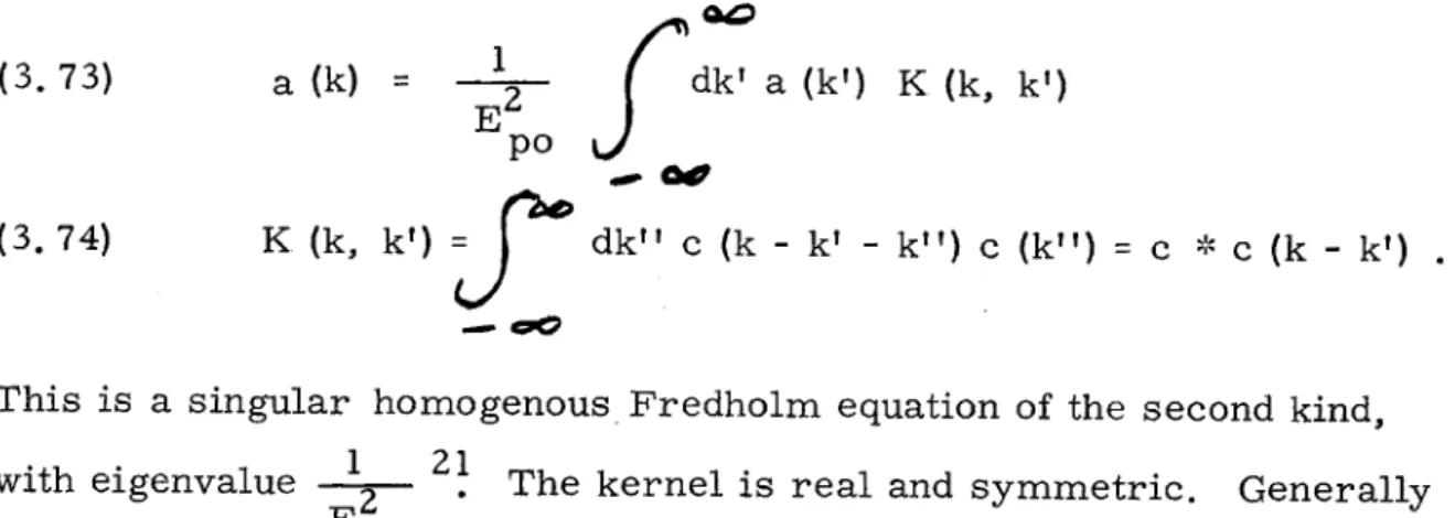
In the limit L- oc , these Fourier series become Fourier integrals so that (3. 72) becomes: a (k) K (k, k') dk' a (k') Eof poU K (k, k') dk'' c (k - k' - k') c (k')= c * c (k - k')
This is a singular homogenous Fredholm equation of the second kind, 1
with eigenvalue I2 po
21
The kernel is real and symmetric. Generally
the eigenvalue spectrum is continuous, with certain conditions depending on the kernel, so that we can superpose the eigenfunctions to form
arbitrarily shaped solutions, just like Fourier integrals. For the field distribution in the focal region:
c (k) = (c z cos k z - E' -0po = E' 1 + ) - k KK 1 x> 0 where f(x) 0 x = 0 Q x(k 4c(k) - K
. Hence c (k) looks like fig.
E' po
I
(a) 2 K 7 (a): c * c(k) 4K2 W. SK (b)fig. 7: The Fourier Transform of the Field in the Focal Region c (k) and its Self-Convolution c * c (k).
(3. 72) (3. 73) (3.74) (3. 75) sin K z K z - 13 k +2K. I ah rl_ P C I
Clearly c (k) Clealy (k --,*spo -- ~>(k) as K-30 and E' -> E which is a trivial
po
reduction to the previous problem. The kernel of the focal region is therefore (fig. 7 (b) ):
c * c (k) =
E'2
(2 K - Ik )H (2 K - Ik) 4K2
where H is the Heaviside function. Hence (3. 73) becomes: E 2 a (k) = po E 2 po 1 4K k+2K k-2K dk' a (k') (2K - k - k'
I)
Upon differentiating twice, this becomes the differential equation:
2 E' 2
(3. 78) 2 po I a (k + 2K) - 2a (k) + a (k - 2K .
dk E 4K2
p0
+ ik z0 Solutions will be of the form a = a e
0
where the transcendental equation
E'
zo = E~ 0o 0 E
or U (z) =
(z
-z ),
sin K zo
is the eigenvalue condition. Since
47
E p=
v + 2 s , (3.79) determines how quickly the mode z0 will grow. In order for there to be asolution to (3. 79), clearly E < El must obtain. For z 4 , solution to (3 79), clal B ms ban o
E B E is independent of z0 , implying modes localized in the focal po~ ~0
region grow at the same rate as expected from the plane wave solutions. Modes with zo> 1 (located away from the focal region) grow more
(3. 76)
(3. 77)
(3. 79)
slowly, with the modes localized near the nodes e = not growing 0 K
at all. One should note that we have assumed the growth factor g (0, t) is independent of k, which breaks down when k -s&k cd. Indeed there will be a cutoff to the spectrum at kc 2 Lc ,corresponding to the
c
highest mode excitable. Hence U (z) is smeared out by an amount
A
L ~ Lc from an exact Dirac delta function.Again a is determined only by noise, with nonlinear satura-tion effects ultimately limiting its steady state value. The problem of exactly how oscillations build up from noise can become important under certain conditions. For instance, if the laser pulse is of such a short duration that the sound wave does not have sufficient time to propagate a long enough distance to establish the feedback necessary for the onset of oscillation, transient solutions arising from the noise will dominate the behavior of the waves. The criterion for this to happen is that
L = vs O, where -r is the pulse duration, is less than Lc, the shortest length of oscillator that will still make it unstable. For a laser pulse of O= 2 x 10⁻⁸ sec, the sound wave travels a distance Lt = 1. 2 x 10⁻² cm
>. Lc = 1 x 10⁻³ cm for the focal region, so that instability will occur for most of the plane wave modes. However, since the effective length of the "active" region La = 1. 1 x 10⁻² cm is comparable with Lt, transient effects may be important for the lowest modes. Transient effects will probably also be important when the laser beam is weakly focussed or unfocussed.22 We can introduce the effect of noise by inserting a term 0 2 1 into (3. 73), corresponding to a
11/4 + k T
uniform excitation of all modes k (true at high temperatures). This makes the integral equation inhomogeneous and unique solutions are then possible2 3
-48-Kroll has treated this problem in another way in the case when the laser field is constant1 4. He starts with (3. 30) and (3. 31) without transformation. Let us extend his method to allow for focal-region variations in
(3.80)
field intensity. Let
U = a - vs t w = a +v t 5 u= -
c.
t 1 1By the chain rule of differentiation
-vs a
1
+
Cl z
- 2 a wai and so that (3. 30) and (3. 31) become:2 c%
43
s w -2 c .8ll-P + so so a ~so + = E. E s 10 po E = Pso ELet us obtain the Green's function for (3. 81):
s + 2 + 6 fdw
Iwo
w 0 + G 2 v s s e~ 4 vs v (w - w ) 0 H (w-w) . (3.81) (3. 82) (3. 83) (3. 84) -w) 0 CPC + 2 G Sso 2vs Hence (3. 85) ='1 2 v s ?W G s 12) Gs GsSuperposition gives: Ps (u, w)= v s 5 w -4 w(w-w dw 0F E io(u, w 0) E po(u, w0) e 4vs 0
Changing the variables and using z - v t = u = - v t :
Ps0 (%, t) z S s f Similarly for (3.88) Vs de0 E. (eo, t - - j0)) Epo , t - 1( (.-00))e
E we get:
E o (.a, t)
d&z P 0 50o0 (VI , t + I(*-JA C. 0 0 o 0 )) Eo(00., t + I(e-* ))eC. 0
+1'
4 ~%
Physically, this says that the solution is a superposition of properly retarded sources originating from the coupling of the waves. We re-strict ourselves to the case of a finite medium which has a boundary (without Fresnel reflection) at - = 0. The other boundary is not important if L -* io . Hence we replace the lower limits of
inte-gration of (3. 87) and (3. 88) by o = 0. We introduce noise sources
g t - t
0(3. 87) and 0
tuting (3. 87) into (3. 88) we then get:
-
t E. (e, t) = A e 10 0 to (3. 88). Substi-_92cs - 2t + B e 2 0 (3.86) (3. 87) 2 c. -- S (3. 89)I
-50-4 .cdo, des E o(01, t + C( - -V (*-o)
4 v 1 s 0 0 + - - ) - -E p0 (01, t + 1' (-e )) e~ 1 -4 1 . lv 10I 1 S v 14
Kroll has solved this for the case -- j; 0 and c1 0 by iteration His results indicate that for - , the growth factor is
exp 2 z instead of the usual exp 7
fr1 )
(see (3. 58) and (3. 64)). The growth factor can be measured by
studying the intensity of stimulated Brillouin scattered light from long liquid cells using an unfocussed laser beam as a function of length of
50