Any correspondence concerning this service should be sent to the repository administrator:
[email protected]
To link to this article : DOI:
10.1016/j.proci.2016.06.138
URL : http://dx.doi.org/10.1016/j.proci.2016.06.138
This is an author-deposited version published in:
http://oatao.univ-toulouse.fr/
Eprints ID: 17717
O
pen
A
rchive
T
oulouse
A
rchive
O
uverte (
OATAO
)
OATAO is an open access repository that collects the work of Toulouse
researchers and makes it freely available over the web where possible.
To cite this version: Mejia, Daniel and Bauerheim, Michaël and Xavier,
Pradip and Ferret, Bernard and Selle, Laurent and Poinsot, Thierry
Stabilization of a premixed laminar flame on a rotating cylinder. (2017)
Proceedings of the Combustion Institute, vol. 36 (n° 1). pp. 1447-1455.
ISSN 1540-7489
Stabilization
of
a
premixed
laminar
flame
on
a
rotating
cylinder
D. Mejia
a,∗, M. Bauerheim
b, P. Xavier
a, B. Ferret
a, L. Selle
a,c,
T. Poinsot
a,caUPS; IMFT (Institut de Mécanique des Fluides de Toulouse), Université de Toulouse; INPT, Allée Camille Soula,
F-31400 Toulouse, France
bLMFA, Ecole Centrale de Lyon, 36 Avenue Guy de Collongue, 69130 Ecully, France cCNRS, IMFT, Av. C. Soula, F-31400 Toulouse, France
Abstract
Thispaperinvestigatesthestabilizationofalaminarpremixedflameonarotatingcylinder.Experimentsand DNSarecombinedtoanalyzetheeffectsofrotationrateontheflowtopologyandflamestabilization.Both experimentandsimulationreveal thattheusualstabilizationpattern(twosymmetricflamerootsonboth sidesofthecylinder)isstronglyaffectedbyrotation.Theflamerootspositionontheupperandlowersides ofthecylinderaremodifiedwithincreasingrotationspeeds.Oneofthetwoflamerootsisquenchedovera longregion.Thedistancebetweentheflamerootsandtheflameholderchangeswiththerotationspeeduntil abifurcationtakesplace:atacriticalrotationspeed,theflamerootsmerge,andtheflamestabilizesupstream ofthecylinder.DNSresultsareusedtoexplaintheflametopologiesobservedexperimentally.
Keywords: Laminarflame;Experimentalcombustion;DNS;Rotatingcylinder
1. Introduction
Flowdynamicsbehindrotatingcylinders[1,2]is a classical topic in non reacting flows, where rotation can promote or mitigate hydrodynamic instabilities[3,4].Flamesstabilizedbehindrotating cylinders (FSBRC) havebeenmuchless studied. Nevertheless,FSBRCconfigurations(Fig.1)have practicalandtheoreticalinterests:(1)Newengine
∗Correspondingauthor.Fax:+33534322991.
E-mail address: [email protected](D.Mejia).
concepts, such as wave rotors [5] or constant-volume combustion chambers [6], are currently developed to increase combustion efficiency and reducepollutantemissionsofmoderngasturbines. Theyinvolverotatingvalves,whichintermittently open/close the combustion chamber inlet and outlet.Thesesituationsmayleadtoflameswhich anchor on these valves, and are pulled by them intothefeedingchamber,leadingtoflashback.
(2)Fromafundamentalpointofview,FSBRC constituteaconfigurationwhichchallengesour un-derstanding of flame/wall interaction and flame stabilization.In aFSBRC (cf.Fig. 1),the flame
Upper Flame
Lower Flame
Fig.1.SketchoftheIntrigsconfigurationwiththeparameterscontrollingtheflowtopology.
rootattheuppersideofthecylinderhasto stabi-lizeinaboundarylayerflowwhichpushesit down-stream,whiletheflamerootlocatedonthelower sideispulledupstreambythecylindermovement. Theflameroots(thepointswheretheflameanchors nearthecylinder)controlnotonlythemeanflame position,butalsoitsdynamicsasshownrecently forlaminar[7–9]andturbulentflames[10].
(3)Introducingrotationintheconfigurationof
Fig.1hasanothereffect:itbreaksthesymmetryof theflow.Symmetrybreakingcontrolsthedynamics ofmanynon-reactingflows[11]aswellas combus-tioninstabilities [12],sothatrotatingflame hold-ersmaybeusefulforcombustioninstabilities con-trol.TodescribeFSBRCs,itisusefultorecall re-sultsobtainedfornon-reactingcaseswheretheflow behindarotatingcylinderiscontrolledby(1)the ReynoldsnumberRe=ubd/ν,(2)therotationrate
α =ωd/(2ub),(3)theblockageratioθ =d/hand
(4)theeccentricity γ =(yc−h/2)/(0.5(h−d ))=
(2yc/h−1)/(1−θ).Forafixedunconfined
cylin-derat zeroeccentricity(ω=0andγ =0),when acriticalReynoldsnumber,Rec≈40,isexceeded, vorticesareshedbehindthecylinder.Fora con-fined cylinder, the critical Reynolds number de-pendsontheblockageratio[13].However, when thecylinderis rotating,theVon Karmannstreet remainsonlyatlowrotationrates(α <2),andis inhibitedatlargerrotationrates(2<α <4).For thepresentstudy,onlyflame-holderslocatedatthe centerofastraightchannelwillbeconsidered,i.e.
γ =0.
Thesituation becomesmorecomplexin reac-tiveconditionssincetheflamecancouplewiththe vorticalflow.ChaandSohrab[14]studiedsucha casewheretherotationalaxisisnormaltotheflame front.Theyshowedthatrotationenhancesthe pre-mixedflamestabilization(blow-off andflashback limits).However,noreactivecasehasbeenstudied wheretherotationaxisisalignedwiththeflame.
Thispaperdescribesanexperimental investiga-tion of the stabilization of a 2D lean premixed methane–airflameonarotatingcylinderfor0<
α <5,atmoderateblockageratio(θ =0.235)and withouteccentricity(γ =0).Two-dimensional Di-rect NumericalSimulations (DNS)are also per-formedtoanalyzetheflametopologyand quench-ing,dependingontherotationrateα.Forafixed cylinder (α =0), a classical stabilization mecha-nism isobserved.Forlowrotationrates(α <4), thesymmetryof theflameisbrokenandtwo dif-ferentbehaviorsareobservedforthetwobranches of theflame.Atlargerotationrates(α >4),the flamestabilizesupstreamof thecylinder.The ge-ometryof theexperimentalbenchispresentedin
Section 2, and the numerical setup for DNS in
Section3,followed bytheexperimentalresultsin
Section 4.The stabilization mechanisms are pre-sentedanddiscussedinSection5.
2. Configuration
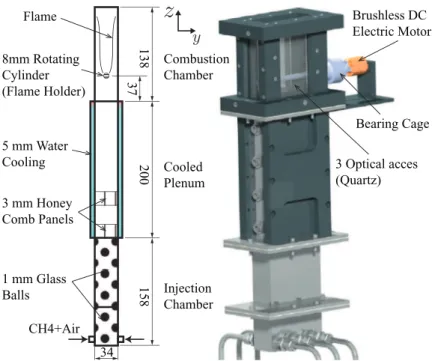
TheexperimentalbenchispresentedinFig.2:a leanpremixedlaminarmethane–airflameis stabi-lizedinthewakeofad=8mmstainlesssteel ro-tatingcylinder.Thecylinderhasbeengrindedand therugosityislessthan1µm.Theburner hasa constantcrosssectionofh=34mmbyl=94mm. Thereactantsarepremixedinaone-meterlong in-jection tube andequally distributed tosix injec-tors placedatthebottomof theinjection cham-ber.Theflowislaminarizedbyanarrayof small glassballsandtwohoneycombpanelsandpasses through thecooledplenum to ensurea constant fresh-gasestemperature.Finally,itentersthe com-bustionchamberwherethecylinderislocated.The rotatingcylinderisplacedinasealed-bearingcage anddrivenbyabrushlesselectricDCmotor.The enginespeedrangesfrom600to20,000rpm.The combustionchamberhasoneopticalaccessatthe front,andoneoneachlateralsides.Inthisstudy, onlyoneoperatingpointwasconsidered:8 =0.75 andub=1.07m.s−1.Theassociatedlaminarflame
speedandadiabatictemperatureares0
l =0.23m/s
CH4+Air Injection Chamber Cooled Plenum Combustion Chamber 138 200 158 37 1 mm Glass Balls 3 mm Honey Comb Panels 5 mm Water Cooling 8mm Rotating Cylinder (Flame Holder) Brushless DC Electric Motor Bearing Cage 3 Optical acces (Quartz) 34 Flame
Fig.2. Transversecut(left )andisometricview(right )oftheIntrigsburner.
afixedcylinder(α =0),theflameissteady.Flames areimagedonanintensifiedPCO-Sensicam cam-eraequippedwithaCH∗narrowband-passfilter
andaf/16180mmtelecentriclens[15].The cam-eraaxisisalignedwiththecylindercenterlineaxis (x).
3. Numericalsetup
To analyze experimental results, a DNS was also performed. The compressible code AVBP is used to solve the multi-species Navier–Stokes equations with realistic thermochemistry on un-structured meshes [16]. Numerics are based on atwo-stepTaylor–Galerkinfinite-elementscheme calledTTG4A,whichisthird-orderinspaceand fourth-order in time. A two-step mechanism for methane–air is used containing 6 species, based onthemethodologydescribedin[17],where adi-abatictemperatureandlaminar flamespeedhave beenvalidatedagainstadetailedchemicalscheme. Schmidt andPrandtl numbers areassumed con-stant. The NSCBCapproach [18] is usedto im-poseacousticboundaryconditions[19]atthe in-let(imposedvelocityu′=0)andoutletboundary
(imposedpressurewithalengthcorrection,p′=0).
Sidewallsaretreatedasno-slipwithaheatflux, ϕw=(T−Twside)/Rw, corresponding to an
im-posedwalltemperature,Tside
w =300Kandaheat
resistance,Rw=10−2K.m2/W.Heatlossesarealso
appliedontherotatingcylinder,withthematerial
temperatureobtainedfromtheexperiment:Twcyl=
610K. The rotation isaccounted for by imposing a velocity~u(θ )=αub~eθatthesurfaceofthecylinder.
Thesimulationisperformedina2Dslicethatstarts attheinletoftheplenumandendsatthechamber outlet.Itcontains1.7millioncells,withaminimum cellssizeof100 µmand5cellsintheflamefront.
4. Experimentalresults
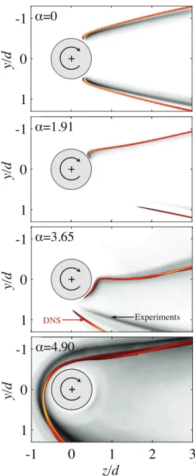
First,theglobaleffectofrotationontheflame topologyisstudiedbyusingseveralrotationrates fromα =0to5.Theflameisfirstignitedatα =0. Oncethermalequilibriumisreached,therotation rateisincreasedinsmallsteps.Threedifferentflame topologiescanbe identifiedinFig.3:forafixed cylinder(α =0,Fig.3top)theflameisstationary andsymmetric:thisflameshape isreferredtoas SymmetricStabilizedDownstream(SSD).Forlow rotationrates(α <4,Fig.3,center)theflame stabi-lizesdownstreamoftherotatingcylinder,and ex-periences astrong dissymmetry:the upper flame rootmoves clockwisealong the cylinder, but re-mainscloselyattached.Thelowerflamerootis al-mostquenchedandtheflamestartsproducinga no-ticeablelevelofCH∗emissiononlyfardownstream
ofthecylinder.Thisflametopologyisreferredto asAsymmetricStabilizedDownstream(ASD).For largerrotationrates(α >4,Fig.3bottom),a tran-sitiontakesplaceandtheflame movesupstream of the rotating cylinder: this situation is named
Fig. 3.The three FSBRC topologies observed experi-mentally:SymmetricStabilizedDownstreamflame(SSD,
top ),Asymmetric StabilizedDownstreamflame (ASD,
center ), and Asymmetric Stabilized Upstream flame (ASU,bottom ).
Fig.4. SketchoftheASDtypeflamewiththeparameters describingtheflametopology.
AsymmetricStabilized Upstream (ASU). In this configuration,theflamerootshavemergedanditis anewstabilizationregimewherethevelocity pro-filesandthevortexgenerationarecompletely dif-ferentfromtheclassicalstabilizationdownstream ofabluff-body.
Thecriticalrotationrateatwhichtheflame tran-sitionsfromASDtoASUiscalledα∗.Testsshow
thatα∗isgovernedbytheratiou
b/s0l.Morethan
100rotationrateshavebeentested,fromα =0to 5,leadingtoflametopologiessimilartoFig.3.In thepresentexperiment,theflametransitionsfrom ASUtoASDinanarrowrange:3.98<α∗<4.15.
When the flame is stabilized downstream, its topologycanbedescribedbythetwoflameroots positions.Inordertostudytheeffectofα,the po-larcoordinatesoftherootsaredefinedinFig.4:β
Fig.5. Flamerootanglesβ(top )anddistancesξ (bot- tom )functionoftherotatingrateα.(——-)upperflame, (---)lowerflame(seeFig.4forangleanddistance def-initions).DNSresultsfromSection5arepresentedas× fortheupperflameand,forthelowerflame.
istheanglebetweenthezaxisandtheflameroot, andξ,thedistancetothecenterofthecylinder.The upperandlowerrootsareidentifiedwithsubscripts 1and2,respectively.Intheexperimentalimages, theflamerootisdefinedasthelocationwherethe gradientoflightintensity(measuredthroughCH∗
emission)ismaximum[9,20,21].Figure5showsthe evolutionsoftherootslocationversusαforthe up-per andlowerflames.Eachcurvecorresponds to themeanvalueoffourdifferenttestsperformedon differentdays.Thecorrespondingerrorbaristhe standard deviationbetween thefourexperiments. SnapshotsoftheflameshapesareshowninFig.6, to be compared with DNS results in Section 5. Regarding theupperflame,ξ1 isalmostconstant
meaningthattheflameisalwaysanchoredtothe cylinder. However, its angle β1, consistently
de-creaseswhenαincreases.Forlowrotationsrates(α <1.5),theflamelocationisunchangedbutξ1then
decreasesrapidly.Forlargerotationrates(α >3.2), theupperflameisactuallyanchoredonthelower sideofthecylinder:theflamerootisdraggedinthe directionofthecylinderrotation.Thelowerflame exhibits a very distinct behavior (Fig.5): its an-choringangleislessaffectedbytherotationwhile itsdistancetothecylindervariesdrastically.ξ2
in-creasesrapidlyuntilamaximumvalueof1.5datα ≈1.3.With a furtherincrease of therotation rate, theflamealmostreattachestothecylinder,before transitioningtoanASUtypeflame.Onemay ques-tiontheexistenceof aflamebetweenthecylinder andtherootdefinedasthelocationofmaximum gradient of CH∗ intensity.However, its emission
levelbeingordersofmagnitudelowerthanthe re-mainderoftheflamefront,itisnotconsideredas aflamefront.Itisworthnotingthatfornonzero valuesof α,theupperflameismoreintensethan the lower flame.This resultsuggests thatthe re-actantsaremainlyconsumedbytheupperflame.
Fig.6.SnapshotsofnormalizedCH∗flameemissionand
normalizedDNSheatreleaseratefields,forfourdifferent rotationrates:α =0,1.91,3.65,and4.90.
Thismechanismwillbeaddressedinmoredetailsin
Section5.
5. DNSanalysisoftheASDquenchedflame Inthe ASD state, where the two flame roots remaindistinct,theresultsof Figs. 5and6raise multiplequestionsbecausetheflamestructures ev-idencedin all previousimages are very different
fromusuallaminarflames.Themostimportant is-sueistoidentifythemechanismsthatmayleadto theflamerootstructuresobservedontheupperand lowerbranches.Flamestretch,dilutionof the un-burntgasesbytheburntgasesandheatlossesto thecylinderarethethreeobviousphenomenathat mayexplainthesestructures.Atlowrotationrates, thelowerbranchquenchingdistanceismuchlarger thanusual.Suchaquenchedzonecanbeexplained eitherbyanexcessivestretch,dilutionorheatloss (oracombinationof thethree).These questions arenowaddressedvianumericalsimulation.DNS wereperformedforvariousrotationratesand es-sentiallyproducedthe sameresultsasthe exper-iment. Figure6 presents the flame topology ob-tainedbyDNScorrespondingtotheexperimental results.Theagreementisgood,βandξarewell pre-dicted(c.f.Fig.5).Inparticular,quenchinginASD flamesformoderaterotationrates,andupstream flamestabilizationforhigherrotationspeeds,are wellcaptured.Nevertheless,discrepanciesare ob-servedforα =1.91and3.65:whiletheupperflame is well described, the lower flame have the cor-rectdistanceξ2butnottherightangleβ2(β2DNS=
72° whileβ2E XP=56°,atα =3.65).This
discrep-ancymaycomefromthereducedkinetic mecha-nismusedintheDNSortheinabilityoftheCH∗
chemiluminescencetocapturelocal flame extinc-tions[22].
Oncevalidated,theDNScanbe usedfor de-taileddiagnostics,usingquantitiesvirtually impos-sibletoquantifyexperimentally.Here,theanalysis islimitedtothequenchedbranchofthetwoflame rootsatα =1.91 and3.65.These twocaseshave beenchosenbecausetheyhaveverydifferent stabi-lizations.Atthelowerrotationrateα =1.91,the lowerflameisfurtherdownstreamthanthecaseof higherrotationrate,α =3.65.
5.1. Flamestretch
Onemechanismthatcouldexplainthe quench-ingofthelowerflamebranchisstretch.Thiseffect issignificantforcounterflowflames[23],in partic-ularonflamespeedandquenchinglimits.Figure7
corresponds to asteady state axial velocity field withthecorrespondingstreamlines.The stream-linesshowthat,forbothcases,therotatingcylinder carriesburntgasesfromtheupperflametowards thelowerflame branch.The burntgasescoming fromtheupperflamemeetthefreshgasesand cre-ateacounterflow.Thestretchiscalculatedin trans-verseplaneoftheflamefront(ζ-directioninFig.7), ζisthecurvilinearabscissaedefiedasthemaximum oftheheatreleaserate,ortheprolongationofthe lowerflamefront.Thestretchκ,isdefinedas: κ(ζ )=−~n~n:∇·~u+sd(∇·~u) (1)
where~uisthevelocityfieldwithitsaxialcomponent
uandtheverticalcomponentv,~nisthedirection normaltotheflamefrontandsdisthedisplacement
-4.3 5.7 u ]s / m[
Fig. 7.DNS steady state 2D axial velocity field with thecorresponding streamlines forα =1.91(top ) and α =3.65(bottom ).
Fig.8. Stretch,κ,fromEq.(2)alongthelowerflame ab-scissaζofthelowerbranch,indicatedbyablackdashed lineinFig.7.Forboth,α =1.91(——-)and3.65(---). Theζcoordinateofthelowerflamerootarerepresented by(,)forα =1.91and(•)forα =3.65.
speed.ForastationaryflameEq.(1)becomes: κ(ζ )=∇t·~ut=tx2 ∂u ∂x+txty µ ∂u ∂y+ ∂v ∂x ¶ t2 y ∂v ∂y (2)
where~tisthedirectiontransversetotheflamefront, as shown in Fig. 7. The values of stretch from
Eq.(2),forbothα =1.91and3.65,areplottedin
Fig.8.Forthelowrotationrate,stretchatthelower flameroot has avalue of κ ≈250s−1.The
criti-calstretch forthe methane–airflame quenching, atthisoperatingpoint,isfoundtobearoundκc=
4000s−1[24,25].Therefore,itisunlikelythatstretch
isresponsiblefortheflamequenching.Moreover,
Fig.8alsoshowsthatatthehigherrotationrate, theflamecanwithstandstretchlevelsof 750s−1,
givingfurtherindicationthatstretchisnotlikelyto beresponsibleforthelocalextinction.
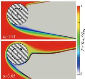
Fig.9.DNSreducedfuelmassfractionfield,F α =1.91 (top )andα =3.65(bottom ).
5.2. Dilution
Another aspect that could explain the flame quenching of thelowerbranchisthedilution of theunburnt gasesbytheburntgases. An indica-torforthedilutionisthereducedfuelmass frac-tionF=YCH
4/Y
u
CH4,whichisbasedontheinitial
fuelmassfractionintheunburntsideYu
CH4.Fgoes
fromoneintheunburntgasestozerointheburnt gases. A2Dfieldof thereducedmassfractionis showninFig.9.Therotatingcylindercarriesburnt gasestowardsthelowerflamebranch.Theseburnt gasesimpacttheunburntgasesandcreatea stagna-tionpointbutnotsignificantdilutionisobserved. The border between thefreshandburntgasesis clearlyseen.Ontheotherhand,forhighrotation rates (α =3.65) someof the burntgasesare en-trainedallthewayaroundthecylinder.This phe-nomenacreatesadilutedzoneintheunburntgases of theupper flamewhereF<1.Itsuggeststhat thereexistacriticalrotationrate,atwhichtheupper branchburntgases,makeacompleterotationand mixbackwiththeincomingunburntgases. Unfor-tunately,thisphenomenondoesnotseemtoexplain thequenchingofthelowerbranchatlowrotation rates.
5.3. Heatlosses
The cooling of the burntgasesbythe “cold” cylinder couldalsoexplain thequenchingof the lower branch. The reduced temperature, 2 is displayed in Fig. 10. 2 =(T−Tu)/(Tb−Tu)
is basedon the unburnt (Tu) andburnt mixture
temperatures (Tb=T
ad, i.e. the adiabatic flame
temperature). 2 goes from zero in the unburnt gasestooneintheburntgases.Thereduced tem-perature field showsthattheburntgases carried
Fig. 10.DNS reduced temperature field obtained for α =1.91(top )andα =3.65(bottom ).
from the upper flame are cooled as they travel along the “cold” cylinder walls (Twcyl=610 K).
For the low rotation rate (α =1.91) the region of lowtemperature(lessthantheadiabaticflame temperaturei.e. iso-contour2 = 0.8in Fig.10), isbiggerthaninthecaseofahigherrotationrate (α =3.65). This region of low temperature may explain why the lower branch is quenched, and itsuggeststhatthereisasignificantlylargerheat fluxfrom theburnt gasesto the cylinderat low rotationrates.IntheDNS,thecylinder tempera-tureisimposedandconstantforallrotationrates. This cylinder temperature, Twcyl, was measured
experimentallyforthedifferentrotationrates.The variationof Twcyl withαiswithintheuncertainty
ofthemeasurements±50°K.Anefforthasbeen focusedonreducingthisexperimentaluncertainty, aswellastheimplementationof thejoint resolu-tionofcombustionandheattransferinthesolid bycoupledsolvers.However,untilnow,thereason why thelow temperature region is larger at low rotationratesisstillnotwellunderstood.
5.4. Enthalpylosses
Aproperquantitytovisualizethiseffect com-bining dilution and cooling due to the rotating cylinder,istheenthalpylossL[26],definedas:
L=2 +F−1, (3)
Foradiabaticcaseswithaone-stepchemistryand aunitLewisnumber,L=0.Thefieldofenthalpy lossL isshowninFig.11forbothcases.As ex-pected,itgoes tozero farfromthecylinder and side-walls.Inthecaseofα =1.91enthalpylossis evenslightlylargerthanzerofortheupperflame, whereasmallheatingofthefreshpremixedgases
Fig.11. EntalphylossfieldL=2 +F −1,obtainedfor α =1.91(top )andα =3.65(bottom ).
Fig.12.ReducedheatreleaserateH(top )andenthalpy lossesL(bottom ),alongthelowerflameabscissaζofthe lowerbranch,indicatedbyawhitedashedlineinFig.11. Forboth,α =1.91(——-)and3.65(---).Theζ coor-dinatesofthelowerflamerootarerepresentedby(•)for α =1.91and(,)forα =3.65.
(initiallyatTu=300K)takesplacenearthe
cylin-der.Thiseffectisnotseeninthecaseα =3.65 be-causeathigher rotationratestheburntgasesare draggedupstreamofthecylinder(Fig.9bottom). Therefore,theeffectof dilution(reductionof F) overcomestheeffectofpreheating(increaseof2). Thisregionoflowenthalpyintheupperpartofthe cylinderexplainswhytheupperflamefrontisless intenseatα =3.65thanatα =1.91.
Toquantifytheeffectsduetoenthalpylosseson theflamequenching,thereducedheatreleaserate H=HR/HRmaxandtheheatlossesL,areplotted inFig.12,alongthecurvilinearabscissaeζofthe
lowerbranch.Enthalpylossreacheslargenegative values(−0.8)nearthebottomoftherotating cylin-der,indicatingamassiveeffectofheatlossesforthe lowerflame.Theflamerootisdefinedhereasthe locationofthemaximumoftheheat-release gradi-ent,thispointcorrespondtoavalueofL≈ −0.2, forboth,α =1.91and3.65.WhenLreaches val-uesof theorderof −0.2,flamequenchingcannot beavoided.Thelowerflamecanonlystartburning whenLincreasesagaindownstreamof the cylin-der.Thisinertmixturecorrespondstotheregion envelopedbytheisocontour−0.2inFig.11.This region ismuchlarger forα =1.91 than it is for α =3.65,whichexplainswhy,atlowrotationrate, thelowerflameispusheddownstream.
Figure9showedthatlittledilutiontakesplace onthelowerbranchofflame.Asaresult,this con-figurationisequivalenttohavinga1Dcounterflow flame,withunburnt gasesononeside andburnt gases with reduced enthalpy on the other side. Withthis analogy,fora given strainrate, if the enthalpyoftheburntgasesisreducedtothelimit ofL=−0.2therewillbeflameextinction.The re-ductionofburntgasesenthalpyismainlygoverned byheat lossesinduced bythe“cold” cylinder so thatflamequenchingiscontrolledbybothrotation rateand heat transfer. The reasonwhy the heat losstothecylinderismoreimportantforα =1.91 remainsunknown,butitisthesubjectofupcoming studies.
6. Conclusion
Thisarticledescribesthefirststudyofthe sta-bilizationofaleanlaminarpremixedmethane–air flameonarotatingcylinder.Fornon-reactiveflows, therotation of the cylinder is known to impact thedevelopmentofinstabilities.Forreactiveflows, bothexperimentandsimulationrevealunusual sta-bilizationpatterns,dependingontherotationspeed ofthecylinder.First,experimentsandsimulations areperformedatseveralrotationrates.Forthe up-perbranchaverygoodagreementforflow topol-ogyandflameshapewasfound.However,forthe lowerbranchtheangleβ2 isnotwellreproduced
bytheDNS.Thisdifferenceisduetothereduced kineticsmechanism usedin thisstudy. Computa-tionswithmoresophisticatedkineticmechanisms willbeconsideredinfuturestudies.Forlow rota-tionspeeds,flamequenchingappearsforthelower flamebranch.UsingDNSresults,thisquenching isfound to be controlled by heat losses: the ro-tation of the flame-holder carries low enthalpy burntproductsfromtheupperbranchtothelower branch,leadingtoflamequenching.Theenthalpy loss,ofthedraggedburntproducts,ismainlydueto theheatlossestothecylinder.Thereasonwhythe heatlosstothecylinderismoreimportantforlow rotationratesremainsunknown.However,thejoint resolutionofcombustionandheattransferinthe
solidbycoupledsolversisunderway.Thisshould giveabetterunderstandingof theinteraction be-tweenheattransferandrotationrate.Athigher ro-tationalspeeds,abifurcationappearsandtheflame stabilizesupstreamofthecylinder.Ongoingworks arebeing performedtocompare DNSdatawith experimentalvelocityfields,andtofurther under-standtheASUstabilizationmechanism.
Acknowledgments
The research leading to these results has re-ceivedfundingfromtheEuropeanResearch Coun-cil under the EuropeanUnion’s Seventh Frame-work Programme (FP/2007-2013)/ERC Grant AgreementERC-AdG319067-INTECOCIS. References
[1] S. Mittal, B. Kumar, J. Fluid Mech. 476 (2003) 303–334.
[2] S.Camarri,F.Giannetti,J.FluidMech.642(2010) 477–487.
[3] J.Guckenheimer,A. Mahalov,Phys.Rev.Lett.68 (1992)2257.
[4] R.Bourguet,D.L.Jacono,J.FluidMech.740(2013) 342–380.
[5] P.Akbari,R.Nalim,N.Mueller,J.Eng.GasTurbines Power128(2006)717–735.
[6] B. Robic, Constant-Volume Combustion (CVC) ChamberforanAircraftTurbineIncludingan In-take/ExhaustValveHavingaSphericalPlug,patent WO2014020275 A1 ,Snecma2014.
[7] K.Kedia,H.Altay,A. Ghoniem,Proc.Combust. Inst.33(2011)1113–1120.
[8] A.Cuquel,D.Durox,T.Schuller,C.R.Méc.341 (2013)171–180.
[9] D.Mejia,L.Selle,R.Bazile,T.Poinsot,Proc. Com-bust.Inst.35(3)(2015)3201–3208.
[10] M.Bauerheim,G.Staffelbach,N.Worth,J.Dawson, L.Gicquel,T.Poinsot,Proc.Combust.Inst.35(3) (2015)3355–3363.
[11] Z. Feng, P. Sethna, J. Fluid Mech. 199 (1989) 495–518.
[12] M. Bauerheim, P. Salas, F. Nicoud, T. Poinsot,
J.FluidMech.760(2014)431–465.
[13] M.Sahin,R.G.Owens,Phys.Fluids16(5)(2004) 1305–1320.
[14] J. Cha, S. Sohrab, Combust. Flame 106 (1996) 467–477.
[15] R.Price,I.Hurle,T.Sudgen,Proc.Combust.Inst.12 (1969)1093–1102.
[16] T.Schönfeld,M.Rudgyard,AIAAJ.37(11)(1999) 1378–1385.
[17] B.Franzelli,E.Riber,M.Sanjosé,T.Poinsot, Com-bust.Flame157(7)(2010)1364–1373.
[18] T.Poinsot,T.Echekki,M.G.Mungal, Combust.Sci. Technol.81(1–3)(1992)45–73.
[19] L.Selle,F.Nicoud,T.Poinsot,AIAAJ.42(5)(2004) 958–964.
[20] V.Kornilov,DynamicsandNonlinear Thermo-Acous-tic StabilityAnalysisof PremixedConicalFlames, TechnischeUniversiteitEindhoven,2006Ph.D. the-sis.
[21] D. Mejia, Wall-TemperatureEffects on Flame Re-sponsetoAcousticOscillations,INPToulouse,2014 Ph.D.thesis.
[22] H.N.Najm,P.H.Paul,C.J.Mueller,P.S.Wyckoff,
Combust.Flame113(1998)312–332.
[23] J.Buckmaster, D. Mikolaitis, Combust. Flame47 (1982)191–204.
[24]B. Coriton, M.D. Smooke, A. Gomez, Combust. Flame157(11)(2010)2155–2164.
[25]L. Tay-Wo-Chong, M. Zellhuber, T. Komarek, H.G.Im,W.Polifke, Flow Turbul. Combust. (2015) 1–32.Springer.DOI:10.1007/s10494-015-9679-0. [26]P.Simon, S.Kalliadasis, J.Merkin, S.K.Scott, J.