OATAO is an open access repository that collects the work of Toulouse
researchers and makes it freely available over the web where possible
Any correspondence concerning this service should be sent
to the repository administrator:
[email protected]
This is an author’s version published in: http://oatao.univ-toulouse.fr/27371
To cite this version:
Mujica, Martin
and Benoussaad, Mourad
and Fourquet,
Jean-Yves
Evaluation of human-robot object co-manipulation under
robot impedance control.
(2020) In: IEEE ICRA 2020- International
Conference on Robotics and Automation, 31 May 2020 - 31 August
2020 (Paris, France).
Official URL:
Evaluation of Human-Robot Object Co-manipulation Task Under
Robot Impedance Control
Martin Mujica1, Mourad Benoussaad1 and Jean-Yves Fourquet1
Abstract—
The human-robot collaboration is a promising and challeng-ing field of robotics research. One of the main collaboration tasks is the object co-manipulation where the human and robot are in a continuous physical interaction and forces exerted must be handled. This involves some issues known in robotics as physical Human-Robot Interaction (pHRI), where human safety and interaction comfort are required. Moreover, a definition of interaction quality metrics would be relevant.
In the current work, the assessment of Human-Robot object co-manipulation task was explored through the proposed met-rics of interaction quality, based on human forces throughout the movement. This analysis is based on co-manipulation of objects with different dynamical properties (weight and inertia), with and without including these properties knowledge in the robot control law. Here, the human is a leader of task and the robot the follower without any information of the human trajectory and movement profile. For the robot control law, a well-known impedance control was applied on a 7-dof Kuka LBR iiwa 14 R820 robot.
Results show that the consideration of object dynamical properties in the robot control law is crucial for a good and more comfortable interaction. Besides, human efforts are more significant with a higher no-considered weight, whereas it remains stable when these weights were considered.
I. INTRODUCTION
Robots are widely used in the nowadays industries with a great variety of purposes thanks to their accuracy, enhanced strength and their ability to repeat movements. From that point, it is natural that new challenges will arise, just as more complex tasks should be handled, where crucial decisions have to be made in real time, or where the robot has to work in non industrial environments (e.g. houses or personal offices). The common issue is the interaction of humans and robots either to share the workspace or to accomplish a collaborative task. Therefore, accomplishing its own purpose, or assisting the person in the collaboration, while assuring the safety of those working along with the robot is the main subject of study of physical human robot interaction (pHRI) The research on the pHRI subject has increased consider-ably over the last decade favored by the advances in hardware development, but also by the increase of applications where a person is involved in the task [1], [2]. This new approach has to deal with many issues as collision avoidance, detection and reaction for eventual interactions and, for the particular case where the collaboration is desired, the amount of force exerted by the robot has to be quantified and handled to do not harm the person. Therefore the control strategy has to 1The authors are with the LGP-ENIT, University of
Toulouse, Tarbes, France; Email: {mmujica, mbenouss, jyfourqu}@enit.fr
be reactive in order to adapt to possible changes ensuring a desired performance and avoiding stability issues [3].
The type of robots to be used depends strongly on the task to be performed. Due to the fact they are widely used in the industry, robotic arms are commonly used in several pHRI applications such as in [4] where a six degrees of freedom robot is used to evaluate a control strategy while people make draws using a pen attached to the robots end-effector. Besides, in [5] the authors implemented two cascade controllers on two different seven degrees of freedom robots to evaluate their performances.
To achieve safe interactions with robot arms, there has been an effort to make them compliant by redefining the materials, configurations and joints producing a new type of lightweight robots (LWR) [6], [7]. These new robot arms are more suitable for collaborative tasks as a consequence of the reduced dimensions, weight, edges and the absence of wires outside the arm. Also, the incorporation of force and torque sensors, along with the usual encoders for the position, enables the implementation of more sophisticated control strategies that take into account the amount of force exerted by the robot.
Despite the modifications in the design of arm robots, safety also has to be considered from the point of view of the control strategy and trajectory planning. So far, in [1] a complete framework consisting of multiple layers (with different levels of hierarchy) has been developed. As it is pointed out in their work, this framework allows to avoid collisions and detect them if they happen. Then it becomes necessary to apply an active compliance at the contact level to manage unexpected interactions or even to allow a collaboration between a person and the robot.
In the last case, the focus is no longer on avoidance but rather into handling the contact in order to keep the exerted forces below an accepted level. This issue is mostly addressed through force control strategies, a field widely developed, but not entirely with the purpose of human robot collaboration [8]. The subject of force control is addressed formally and detailed in [9] where the authors divided the strategies in two categories: direct and indirect force control. The main difference between the two categories is whether the exerted force is regulated by an explicit force feedback loop (direct force control), or if the force is regulated by controlling the robot’s motion (indirect force control).
Allowing a robot to fully collaborate with a person implies a particular and complex layer of human robot interac-tion. Therefore, rendering the robot compliant might not be enough and the diversity of possible tasks to accomplish
should be considered. An early approach to analyse a human-robot cooperative tasks was performed in [10]. The authors used a simple one-dimensional device aiming to show how the level of assistance supplied by the robot impacts on the human comfort in point to point movements. According to the level of assistance desired, the reference velocity of the robot is scaled to reach the estimated that the human would have.
One of the most studied aspects of physical human robot collaboration (pHRC) is rendering the robot transparent for the human. The cases of study used are simple (i.e. no important efforts, no heavy objects) with the purpose of allowing the person to accomplish the task by manipulat-ing the robot’s end-effector (e.g. a drawmanipulat-ing task [4]). The development in [11] evaluated the capacity of a person to follow a labyrinth-like path with a pen attached to a three degrees of freedom parallel robot with an admittance controller implemented. This controller was improved by adapting the damping parameter according to the estimated humans’ stiffness, assuring stability and making the robot more intuitive for the person.
It can be noticed the influence of the damping in the robot’s transparency and stability. Nevertheless, most of the results and improvements obtained consists mainly on allowing the person to have an intuitive collaboration with a robot to perform trajectories, but that does not imply that this methods are optimal to help the person perform a difficult task or carry heavy objects. In these works the goal was to analyze what are the robot’s behaviors that are the most appropriates for a human-robot collaborative task, however, the impact on a person in terms of task simplification is not evaluated. In [12] the authors analysed the scheme of human robot collaboration with no object between them for three different type of movements performed by the human (point to point, periodic, arbitrary), and by proposing variations to the compliant controller to enhance the performance of the collaboration.
Differently, for a table displacement task performed by a human and a robot, an original approach was performed in [13] with the aim of keeping a table horizontal. The authors developed a framework were a combination of a reactive controller and a proactive controller (obtained from the estimation of the person’s behavior) is applied. It is worth noticing that their approach illustrates the possibility of improving the collaborative task with regard to a simple follower, reactive, control strategy. Nevertheless, their work did not consider the forces exerted by the person or the robot, and the table was considered to be light-weighted.
Recently, in [14] a fuzzy impedance control (with force derivative and velocity as inputs) was implemented with the aim of generating a desired position for an internal cartesian impedance controller to follow. By including a desired po-sition while collaborating with a person the stiffness term of the controller can be conserved and therefore, if the estimation was correctly done, enhance the capabilities of the robot. The authors evaluated the controller on a KUKA iiwa using a performance criteria to evaluate the results.
This paper aims to address the difficulties of performing a collaboration with a person to move a non-negligible object and the possible improvements to be made. In the current work, we analyse what are the metrics of a “good” collaboration (i.e. that simplifies the task for the person) by quantifying and comparing the efforts done by the person and the robot during the collaboration, which consists of an object co-manipulation task. The organization of the article is as follows: Section II will introduce some of the theoretical concepts used for the robot’s controller while Section III will be focused on the collaborative scenario and the description of the elements used for the experiments. The results obtained through the experiments performed will be displayed and discussed in Section IV. Conclusions and perspectives of this work will be then summarized in V.
II. PRELIMINARIES
In this section, few theoretical concepts used to apply a robot’s compliant control in context of pHRI are introduced and detailed.
A. Impedance Control
Impedance control has been strongly developed, specially based on Hogan’s work [15], [16] were the theory and implementation to robotics manipulators were described. Even thought the basic idea of controlling the relationship between the robot’s motion and the external efforts (hence reshaping the impedance of the manipulator) is commonly addressed, there have been different approaches according to the task to be performed and the knowledge of the robot’s dynamic parameters.
Following the case of the “dynamic impedance control” (usually named impedance control) the development of [9] aims to achieve a linear relation between the second order dynamic of the error and the external efforts, which would lead to the following closed loop form:
MDx¨˜+ KD ˙˜x + KP˜x= he, (1)
where MD is a positive definite diagonal matrix that
rep-resents the desired virtual inertia of the end effector, KD
and KP are also positive definite matrices representing the
damping and stiffness respectively. The x vector is the˜
6 × 1 cartesian error between the desired pose and the end-effector’s pose, defined asx˜= xd− xewith its derivates, he
is also a6 × 1 vector containing the three forces and three
torques in the cartesian space.
Considering the well known joint space dynamics equation of a manipulator:
M(q) ¨q+ C(q, ˙q) ˙q + g(q) = u − JT(q) h
e, (2)
where M(q) as the Inertia matrix, C(q, ˙q) ˙q is the vector corresponding to the Coriolis and centrifugal terms while g(q) is the gravitational vector, u is the vector of joint controlled torques and J is the geometrical Jacobian of the manipulator with respect to the base frame, the control law u can be defined as it follows:
u= M(q) a + C(q, ˙q) ˙q + g(q) + JT(q) h
so the effects of the Coriolis, centrifugal, gravitational and external forces terms can be compensated (if they were accurately estimated in the first place). Leaving a as the controller part that will define the new closed loop dynamic. By inserting (3) into (2), the expression obtained is:
¨
q= a. (4)
In order to obtain the desired error dynamic behavior of (1), the main part of the controller should be chosen as:
a= J−1M−1
D (MDx¨d+ KD ˙˜x + KPx − M˜ D ˙J ˙q − he),
(5)
where he has been also included to add the linear
compli-ance of the mass-spring-damper system with respect to the external forces.
B. Orientation Control
As described previously, both the real and the desired end
effector’s pose are usually expressed as6 × 1 vectors with
three components for position and three for orientation. Nev-ertheless, it is common to have the orientation represented
by a3 × 3 matrix where only three of the components are
independents. The advantage of the rotation matrix is the easiness to perform algebraic operations, allowing to easily calculate the orientation error by the expression:
˜
R= RdRT, (6)
where R is the actual orientation matrix and Rd is the
desired orientation matrix, both with respect to a base frame.
For the control law, a vector ˜φ with three independent
components representing the orientation error can be
ob-tained from ˜R since it is a skew-symmetric matrix, hence:
˜ φ( ˜R) = 1 2 ˜ φ1 ˜ φ2 ˜ φ3 = ˜ r32− ˜r23 ˜ r13− ˜r31 ˜ r21− ˜r12 , (7)
wherer˜ij are the components of ˜R matrix.
The position error vectorx can then be described as:˜
˜
x= [˜x1x˜2x˜3φ˜1φ˜2φ˜3]T (8)
and its derivative, if infinitesimal rotations are considered, can be represented by:
˙˜x = [ ˙˜x1 ˙˜x2˙˜x3ω˜1ω˜2ω˜3]T (9)
where ω˜i are the errors in angular velocities, which allows
the use of the use of the geometric Jacobian in the control law. A deeper analysis on the different orientation representa-tions, its application to orientation control and the difference between geometric and analytical Jacobian can be found in [17], [18].
Fig. 1. Human robot collaboration to move a box with the robot Kuka LBR iiwa 14 R820.
III. COLLABORATIVE SCENARIO AND EXPERIMENTAL SETUP
One of the main difficulties in human robot interaction is the influence of the task to perform in the control schemes design. For our collaborative scenario, a 7-dof Kuka LBR iiwa 14 R820 robot, dedicated to collaborative applications, is used. The robot will collaborate to move a non-negligible object along with a person, as it can be seen in the Fig. 1. The person, as a leader, applies the object movement and the robot will follow. The direction, velocity and force applied by the human on the object are unknown for the robot, the only information used in the robot’s control is what the robot measures on its own end-effector.
The robot will be controlled through a Cartesian impedance scheme, described by (1), where the three matri-ces are diagonal. The purpose is to make the robot compliant in translation, while keeping the initial orientation of the end effector during the motion. It follows the idea of moving and object without dropping the things that might be inside. For the impedance controller, the inertia matrix was defined as:
MD = 20 0 0 0 0 0 0 20 0 0 0 0 0 0 8 0 0 0 0 0 0 10 0 0 0 0 0 0 10 0 0 0 0 0 0 10 , (10)
based on an analysis of the natural virtual inertia of the manipulator in the Cartesian space while performing the desired trajectory with the box. Since a significant reduction of these values might lead to instability [3], [19], the ones chosen are not considerably smaller, but they lead to a decoupled effect of the inertia between different axis. For the damping and stiffness matrices, the cases of translation and rotation were separated. The damping was chosen identical
in all Cartesian directions of translation (i.e. KDij = 20,
when i= j = 1, 2, 3). In the case of the stiffness matrix it
is remarkable that, in translation, all elements were chosen equal to zero, as it has been mostly done in the previous collaborative experiments [4], [10], [11], [20]. This choice
aims to prioritize the transparency of the robot in translation rather than improving the performance of the task carried out by the person. Since there is no desired position for the robot, as it is the human who is guiding, removing the virtual spring avoids undesired forces that could oppose to the human’s intentions. With the same purpose, the desired position and its derivatives were set to zero. For the orien-tation, the damping was chosen also similar in all directions
(i.e. KDij = 100 when i = j = 4, 5, 6), which penalize
rotational velocities. In the case of the stiffness matrix, the
rotational components were chosen as: KPij = 900 (when
i= j = 4, 5, 6), to minimize orientation errors with respect
to the initial orientation.
The object to manipulate during a collaboration is not often considered since, the purpose is usually to analyse the interaction between the person and the robot. Nevertheless, if the goal is to enhance the collaboration, it has to be consid-ered as an important element of the scenario. Considering the object consists on setting up its geometrical and dynamical properties in the experiment. Two different situations will be distinguished here; In the first, the object is unknown (under certain limitations e.g. not heavier than the robots maximum payload) and in the second, the mass, inertia and geometry of the object are known and included in the robot controller. In this work, both situations will be analyzed with a rigid
empty box of 1.2 kg. Then, to increase the payload, 1 and
2 kg will be added to the box. For simplicity, the additional load was considered homogeneously distributed in the box.
The experiments were carried out with the robot Kuka LBR iiwa 14 R820. The robot was controlled using the
FRI system provided to work under real time constraints.
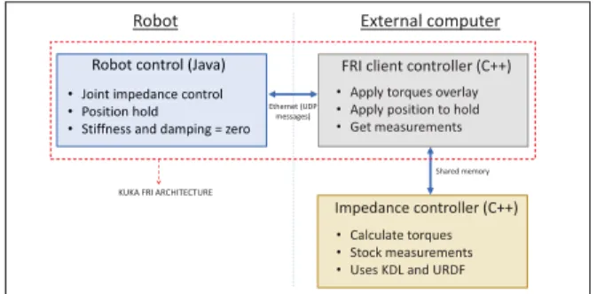
It consists on a predefined architecture, provided by Kuka which allows the communication between the robot and an external client program in another computer. In our case, three different programs can be distinguished, as detailed in Fig. 2, one working in the robot computer that communicates with another one on the external computer, and a third one that will perform the impedance control. This schema was chosen to develop the controller outside the FRI architecture. In this way the controller can be used differently (e.g. in a ROS environment for simulations) and we do not make important modifications to the FRI client program.
The robot side of the controller was set to joint impedance control mode, however, with stiffness and damping set to zero. Therefore it performs only the gravity and coriolis compensation. On the other hand, the external controller (FRI client) applies the torques calculated by the impedance controller and reads the state of the robot in real time
(less than 1ms). The Impedance controller in the external
computer performs the computation of the control law (3) but without the dynamic compensation terms. Since data obtained from robot through FRI is limited (e.g. inertia matrix, Jacobian and end effector pose are not provided),
KDL library1for kinematics and dynamics has been used in
the external controller. Therefore, It will receive only robot’s 1http://www.orocos.org/wiki/orocos/kdl-wiki
FRI client controller (C++) • Apply torques overlay • Apply position to hold • Get measurements
Impedance controller (C++) • Calculate torques • Stock measurements • Uses KDL and URDF Robot control (Java)
• Joint impedance control • Position hold
• Stiffness and damping = zero Robot control (Java)
• Joint impedance control • Position hold
• Stiffness and damping = zero
Shared memory
Robot External computer
Ethernet (UDP messages)
KUKA FRI ARCHITECTURE
Fig. 2. Implementation of the controller on the robot Kuka LBRiiwa 14 R820 through FRI to work in real time.
joint positions and external joint torques, and will send the commanded joint torques from the impedance controller, through the FRI architecture Fig. 2.
IV. RESULTS AND DISCUSSIONS
To be able to compare the performance of the controller with and without the knowledge of the payload, movements
were performed in the Z axis (displacement of 30 cm
upwards and then return). Knowing the variability of human trajectory profile, even with the same load and controller, obtained trajectories are not identical. For each of the two cases (with and without knowledge of the object), three different payloads were considered, and for all of them three experiments were conducted. In all cases the experiment started from the same cartesian position but also the same joint angles.
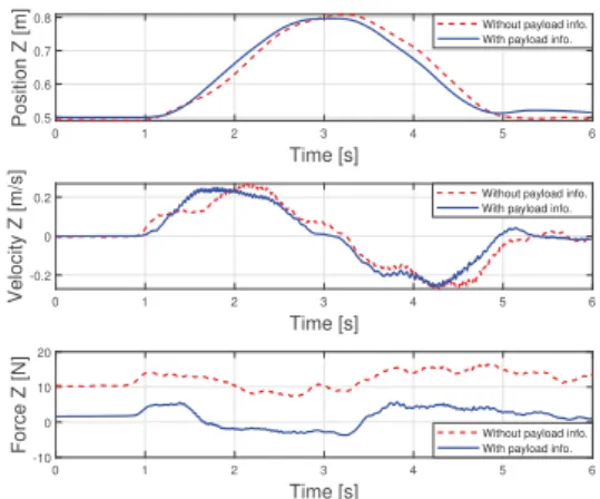
Fig. 3 shows the comparison between the trajectories performed with only the box and the corresponding force applied by the human. In one case the object dynamic properties are known, compensated and included in the controller and not in the other case. Even though the tra-jectories performed are similar, the velocity profiles present some differences. The case of the velocity with the payload considered is closer to the one from the fifth order trajectory polynomial [21] (that is commonly used to represent human’s hand trajectories). When payload information is considered, it is possible to distinguish the positive force at the beginning (in the acceleration phase) to lift the object. Then the force becomes negative to stop the movement and return, where the force is positive again to stop at the initial position. In the case of the payload not considered, the positive forces at the beginning and at end are bigger, because more efforts are needed to start and stop the movements. On the contrary, during the negative acceleration phase (to return to the initial position) the variation of the efforts applied is not so pronounced, mainly because the gravity force working on the object (and not compensated by the robot) helps to lower it.
Besides, in order to analyse the results, some metrics were used along with the force and trajectory curves. This approach differs from the common one where the compar-isons are based on multiple humans feedback. With this objective approach, experimentation with a wide range of people (different gender and age) is not strictly needed.
Firstly, the root mean square (RMS) of the force applied by the person is used as a quantitative indicator of the collaboration’s performance. It represents the amount of effective force applied by the person (since either the force is positive or negative, it will fatigue and disturb the person). In that way, reducing the value would indicate less efforts done by the person to perform the trajectory. Then, the RMS of the power supplied by the person (as a product of velocity and force) is assessed as well. With this mechanical power, the velocity is also considered in the comparison, providing thus extra information about the collaborative task.
The efforts done by the person are estimated based on the external joint torques measured by the robot. From these torques, the cartesian external efforts applied at the end effector can be obtained through Jacobian’s transpose. In the case of the payload considered in the robot’s model, the object is incorporated as part of the last link of the robot. Therefore, the cartesian efforts measured belong entirely to the person. When the payload is not considered, the external measured efforts belong to both the object’s gravity force and the force applied by the person. Since the movement was performed in the Z axis, for simplicity, only this coordinate will be analysed. Then, the estimated external cartesian effort in Z axis can be described as:
hez = Fhz− m g , (11)
where heZ are the measured external force, FhZ is the force
made by the person, m is the object’s mass and g is the gravity acceleration. In that way, the force made by the human can be obtained by adding the object’s gravity force to the results obtained from the measurements of the external force. This can be seen in Fig. 3 where the force made by the person variates around the value of the gravity force acting on the object (11.76 N ). Nevertheless, in the case of Fig. 4
when the3.2 kg payload is not considered, the force should
variate around 31.36 N (object’s gravity force). Instead it
varies around a value close to25 N . This difference, would
show the existence of another force acting on the system. Since the forces performed by the robot do not appear in the measurement of external forces, it would imply the presence of an important unmodeled mechanical friction acting on the robot. This force acts, in this case, carrying some of the object’s load.
In Table I, the comparison for the three different payloads is done. The two cases were analysed: when the payload is completely known and incorporated, and when it is not. For each case, since the experiment was performed thrice, the mean and standar deviation are shown in the table. It can be seen how, when the payload is known, the amount of efforts done by the person do not variate considerably, since the payload is compensated and the controller remains stable. Problems could arise if the payload acquires values
where the desired virtual inertia matrix (MD) in (1) could
not be reached without loosing the stability of the system [3], [19]. As for the case where the payload is not considered, it is clear how the force needed to perform the trajectory are much higher. In fact the forces to compensate the load of
0 1 2 3 4 5 6 Time [s] 0.5 0.6 0.7 0.8 Position Z [m]
Without payload info. With payload info.
0 1 2 3 4 5 6 Time [s] -0.2 0 0.2 Velocity Z [m/s]
Without payload info. With payload info.
0 1 2 3 4 5 6 Time [s] -10 0 10 20
Force Z [N] Without payload info.With payload info.
Fig. 3. Comparison of the trajectories performed with and without knowledge of the object payload (only the box), along with their velocities and forces applied by the person.
the object are dominant with respect to the forces needed to move the object. Therefore, the object’s knowledge and its use in the controller become crucial for a good collaborative task.
As for how the knowledge of the object to manipulate impacts on the robot’s controller performance, two cases were detailed and evaluated. When the payload is known, both the gravity and inertia matrix can be identified and compensated if necessary. Differently, if the object is un-known, while estimating those matrices, they will not match the real ones of the system robot-payload. Moreover, a third case (not analysed in the current work) can be distinguished, where the payload mass is considered in the gravitational term of the controller, but not in the inertia matrix. Not taking into account the modifications produced by this payload in the inertia matrix would lead to a variation in (4), since the matrix M(q) used in (3) is not the same as the real inertia matrix of the robot. An example of this situation could be a robot that can compensate the gravity term of the payload but does not provide the information. Therefore the inertia matrix of the whole robot and payload system cannot be identified. Besides when co-manipulating a box where objects will be added inside, mass and inertia would change continuously, making more difficult the identification of the payload and its characteristics.
TABLE I
RMSOF THE HUMANS FORCE FOR DIFFERENT PAYLOAD VALUES. WHEN
PAYLOAD INFORMATION IS KNOWN FOR THE GRAVITY COMPENSATION
AND CONTROLLER,AND WHEN THE IT IS NOT USED AT ALL.
Load With load info Without load info mean std mean std 1.2 kg 2.73 N 0.62 N 11.07 N 1.31 N 2.2 kg 3.28 N 0.30 N 20.21 N 1.05 N 3.2 kg 2.72 N 0.65 N 28.90 N 0.30 N
The analysis of the forces applied by the human give a perspective of the efforts done by the person, but in a collaboration there are other aspects to consider as metrics
0 1 2 3 4 5 6 Time [s] -10 -5 0 5 10 15 20 25 30 35 40 Force Z [N]
Without payload info. With payload info.
Fig. 4. Comparison of the force applied by the person to move a total load of 3.2kg with and without the information of the payload in the controller and model.
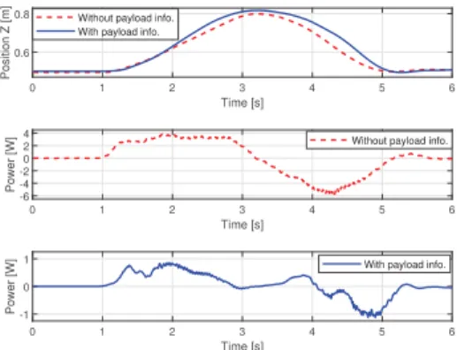
of performance. For instance adequate velocities along with the forces, avoiding unnecessary accelerations or minimizing the jerks can be considered appropriate for the human. In Fig. 5 the instantaneous power applied by the person can be seen along with the trajectory done, for both the payload
known and not known (in this case, a total of3.2 kg). The
mechanical power is calculated as:
Pz(t) = Fz(t) vz(t) (12)
Where Fz(t) is the force applied by the person over the
time and vz(t) is the velocity of the end
effector-object-hand system. Since both the robot and the person try to keep the orientation invariant, the same velocity in the Z axis is considered for the three elements of the system. It can be noticed, specially when the payload is considered, the two moments when the power is negative. This mean that the velocity and the force have different signs, implying that the person is trying to stop the object’s movement. This power applied, both positive and negative, should be reduced in module to ease the task for the person. Therefore for the comparison performed in Table II the RMS values of the power over time were considered. It can be remarked that the tendencies, in the case of not knowing the payload, are similar as the first analysis done over the forces, showing the influence of the payload in the humans effort.
TABLE II
RMSOF THE POWER SUPPLIED BY THE PERSON TO THE OBJECT-ROBOT
SYSTEM. WHEN PAYLOAD INFORMATION IS KNOWN FOR THE GRAVITY
COMPENSATION,AND CONTROLLER AND WHEN IT IS NOT USED AT ALL.
Load meanWith load infostd meanWithout load infostd 1.2 kg 0.41 W 0.17 W 1.60 W 0.16 W 2.2 kg 0.43 W 0.10 W 3.02 W 0.22 W 3.2 kg 0.34 W 0.05 N 3.94 W 0.03 W
V. CONCLUSIONS AND PERSPECTIVES Through this work the influence of the payload’s knowl-edge during a collaborative task was analysed, particularly
0 1 2 3 4 5 6
Time [s] 0.6
0.8
Position Z [m]
Without payload info. With payload info.
0 1 2 3 4 5 6 Time [s] -6 -4 -2 0 2 4 Power [W]
Without payload info.
0 1 2 3 4 5 6 Time [s] -1 0 1 Power [W]
With payload info.
Fig. 5. Comparison of the trajectories performed with and without knowledge of the payload (total load of 3.2kg), and the respective power supplied to the system by the person.
for the case of a vertical axis displacement, not enough studied in the literature. Two different cases were studied for different payloads, the first one, when the object is known and included in the controller, and the other when it is not known. The experiments were performed with a Kuka LBR iiwa 14 R820 robot for collaborative tasks through an impedance controller. The results, obtained from the proposed metrics (different from the traditional humans feedback) show the influence of the payload and the accurate compensation of it in the model. Besides, the influence is also noticed in the inertia matrix during the linearization of the system. Future works will explore in detail this influence and how it might affects stability. Also, the possibility of improving the control law to be more robust to payload modelling errors is expected.
REFERENCES
[1] A. De Luca and F. Flacco, “Integrated control for phri: Collision avoid-ance, detection, reaction and collaboration,” in Biomedical Robotics and Biomechatronics (BioRob), 2012 4th IEEE RAS & EMBS Inter-national Conference on. IEEE, 2012, pp. 288–295.
[2] A. Ajoudani, A. M. Zanchettin, S. Ivaldi, A. Albu-Sch¨affer, K. Ko-suge, and O. Khatib, “Progress and prospects of the human–robot collaboration,” Autonomous Robots, pp. 1–19, 2018.
[3] N. Hogan and S. P. Buerger, “Impedance and interaction control,” in Robotics and automation handbook. CRC Press, 2004, pp. 375–398. [4] K. Kosuge and N. Kazamura, “Control of a robot handling an object in cooperation with a human,” in Robot and Human Communication, 1997. RO-MAN’97. Proceedings., 6th IEEE International Workshop on. IEEE, 1997, pp. 142–147.
[5] C. Ott, A. Albu-Schaffer, A. Kugi, and G. Hirzinger, “On the passivity-based impedance control of flexible joint robots,” IEEE Transactions on Robotics, vol. 24, no. 2, pp. 416–429, 2008.
[6] A. Albu-Sch¨affer, S. Haddadin, C. Ott, A. Stemmer, T. Wimb¨ock, and G. Hirzinger, “The dlr lightweight robot: design and control concepts for robots in human environments,” Industrial Robot: an international journal, vol. 34, no. 5, pp. 376–385, 2007.
[7] R. Bischoff, J. Kurth, G. Schreiber, R. Koeppe, A. Albu-Sch¨affer, A. Beyer, O. Eiberger, S. Haddadin, A. Stemmer, G. Grunwald, et al., “The kuka-dlr lightweight robot arm-a new reference platform for robotics research and manufacturing,” in Robotics (ISR), 2010 41st international symposium on and 2010 6th German conference on robotics (ROBOTIK). VDE, 2010, pp. 1–8.
[8] T. Yoshikawa, “Force control of robot manipulators,” in Robotics and Automation, 2000. Proceedings. ICRA’00. IEEE International Conference on, vol. 1. IEEE, 2000, pp. 220–226.
[9] L. Villani and J. De Schutter, “Force control,” in Springer handbook of robotics. Springer, 2008, pp. 161–185.
[10] B. Corteville, E. Aertbeli¨en, H. Bruyninckx, J. De Schutter, and H. Van Brussel, “Human-inspired robot assistant for fast point-to-point movements,” in Proceedings 2007 IEEE International Conference on Robotics and Automation. IEEE, 2007, pp. 3639–3644.
[11] V. Duchaine and C. Gosselin, “Safe, stable and intuitive control for physical human-robot interaction,” in 2009 IEEE International Conference on Robotics and Automation. IEEE, 2009, pp. 3383– 3388.
[12] Y. Li and S. S. Ge, “Force tracking control for motion synchronization in human-robot collaboration,” Robotica, vol. 34, no. 6, pp. 1260– 1281, 2016.
[13] A. Thobbi, Y. Gu, and W. Sheng, “Using human motion estimation for human-robot cooperative manipulation,” in Intelligent Robots and Systems (IROS), 2011 IEEE/RSJ International Conference on. IEEE, 2011, pp. 2873–2878.
[14] L. Roveda, S. Haghshenas, A. Prini, T. Dinon, N. Pedrocchi, F. Braghin, and L. M. Tosatti, “Fuzzy impedance control for enhancing capabilities of humans in onerous tasks execution,” in 2018 15th International Conference on Ubiquitous Robots (UR). IEEE, 2018, pp. 406–411.
[15] N. Hogan, “Impedance control: An approach to manipulation,” in American Control Conference, 1984. IEEE, 1984, pp. 304–313. [16] ——, “Impedance control: An approach to manipulation: Part
iiimple-mentation,” Journal of dynamic systems, measurement, and control, vol. 107, no. 1, pp. 8–16, 1985.
[17] R. Campa and H. De La Torre, “Pose control of robot manipulators using different orientation representations: A comparative review,” in 2009 American Control Conference. IEEE, 2009, pp. 2855–2860. [18] F. Caccavale, C. Natale, B. Siciliano, and L. Villani,
“Resolved-acceleration control of robot manipulators: A critical review with experiments,” Robotica, vol. 16, no. 5, pp. 565–573, 1998. [19] F. Ficuciello, L. Villani, and B. Siciliano, “Variable impedance control
of redundant manipulators for intuitive human–robot physical interac-tion,” IEEE Transactions on Robotics, vol. 31, no. 4, pp. 850–863, 2015.
[20] F. Ferraguti, C. Talignani Landi, L. Sabattini, M. Bonf`e, C. Fantuzzi, and C. Secchi, “A variable admittance control strategy for stable phys-ical human–robot interaction,” The International Journal of Robotics Research, vol. 38, no. 6, pp. 747–765, 2019.
[21] W. Khalil and E. Dombre, “Chapter 13 - trajectory generation,” in Modeling, Identification and Control of Robots, W. Khalil and E. Dombre, Eds. Oxford: Butterworth-Heinemann, 2002, pp. 313 – 345. [Online]. Available: http://www.sciencedirect.com/science/article/pii/B9781903996669500130