Science Arts & Métiers (SAM)
is an open access repository that collects the work of Arts et Métiers Institute of
Technology researchers and makes it freely available over the web where possible.
This is an author-deposited version published in:
https://sam.ensam.eu
Handle ID: .
http://hdl.handle.net/10985/10280
To cite this version :
Germanico GONZALEZ-BADILLO, Hugo MEDELLIN-CASTILLO, Theodore LIM, James M.
RITCHIE, Samir GARBAYA - The development of a physics and constraint-based haptic virtual
assembly system - Assembly Automation - Vol. 34, n°1, p.41–55 - 2014
Any correspondence concerning this service should be sent to the repository
Administrator :
[email protected]
The development of a physics and
constraint-based haptic virtual assembly system
Germanico Gonzalez-Badillo and Hugo Medellin-Castillo
Facultad de Ingenierı´a, Universidad Auto´noma de San Luis Potosı´, San Luis Potosı´, Mexico
Theodore Lim
Department of Mechanical Engineering, Heriot-Watt University, Edinburgh, UK
James Ritchie
School of Eng and Phys Sciences, Heriot-Watt University, Edinburgh, UK, and
Samir Garbaya
Institut Image, Arts et Metiers ParisTech, Chalon sur Saone, France
Abstract
Purpose – This paper aims to report the development and key features of a novel virtual reality system for assembly planning and evaluation called Haptic Assembly and Manufacturing System (HAMS). The system is intended to be used as a tool for training, design analysis and path planning. Design/methodology/approach – The proposed system uses the physics-based modelling (PBM) to perform assemblies in virtual environments. Moreover, dynamic assembly constrains have been considered to reduce the degrees of freedom of virtual objects and enhance the virtual assembly performance. Findings – To evaluate the effectiveness and performance of HAMS, the assembly of various mechanical components has been carried out, and the results have shown that it can be effectively used to simulate, evaluate, plan and automatically formalise the assembly of complex models in a more natural and intuitive way.
Research limitations/implications – The collision detection performance is the bottleneck in any virtual assembly system. New methods of collision shape representation and collision detection algorithms must be considered.
Originality/value – HAMS introduces the use of dynamic assembly constraints to enhance the virtual assembly performance. HAMS also uses features not yet reported by similar systems in the literature. These features include: automatic or manual definition of assembly constraints within the virtual assembly system; the implementation of control panels and widgets to modify simulation parameters during running time to evaluate its influence on simulation performance; assembly data logging such as trajectories, forces and update rates for post-processing, further analysis or its presentation in the form of chronocyclegraphs to graphically analyse the assembly process.
Keywords Assembly, Virtual reality, Assembly constraints, Haptics, Physics-based modelling, Virtual assembly Paper type Technical paper
1. Introduction
Assembly remains the most studied processes in manufacturing industry because it represents up to 60 per cent of the total cost of the product (Boothroyd, 1992). Computer aided design (CAD) and computer aided assembly planning (CAAP) are still de facto systems to create assembly plans. These systems use various algorithms to automate assembly planning such as feature recognition. In these systems human experience and knowledge are difficult to support intuitively and some factors – such as quality testing, shop floor layout and human ergonomics – cannot be easily taken into account during assembly evaluation (Xia et al., 2013). The lack of physical constraints that the user experiences in the real world, such as collision and interference among objects, is another issue with such systems.
Technologies such as virtual reality (VR) can be used as a tool to enhance the assembly planning and evaluation process by providing a virtual environment (VE) where users can get the feeling of immersion in a real environment and the use of more intuitive cues such as collisions between virtual objects, collisions with obstacles, friction, inertia, restitution, 3D rendering and sound, etc. (Gutie´rrez et al., 1998). The evaluation of assembly/disassembly processes in a VE during the early stages of design helps to dramatically reduce the time, cost and material associated with the construction of physical prototypes (Liu et al., 2010).
VEs can be enhanced with haptic technologies to provide the sense of touch. Force-reflecting haptics create a close-loop system, linking visceral data with human motor and cognition. Haptics is therefore ideally suited to understand the interactions and procedures associated with assembly tasks. It allows natural manipulation of objects by enabling the user with the feeling of virtual object collisions, weight and inertia.
The current issue and full text archive of this journal is available at www.emeraldinsight.com/0144-5154.htm
The authors acknowledge the financial support from CONACYT (National Science and Technology Council of Mexico) research grant CB-154430 and EPSRC/IMRC grants 113946 and 112430.
This paper describes the research and development of a VR system for assembly evaluation and planning named as Haptic Assembly and Manufacturing System (HAMS). The configuration and flexibility of HAMS allows its use as a platform for evaluating the influence of various simulation parameters on the performance of assembly simulation.
2. Related work
2.1 Virtual assembly
Virtual assembly (VA) is defined as:
[. . .] utilizing VR technology, computer graphics, artificial intelligence, assembly theory and method, to construct the virtual model of the product and the VE of the assembly layout, and then interactively analyse and simulate the product design result and assembly operation process (Xia et al., 2013).
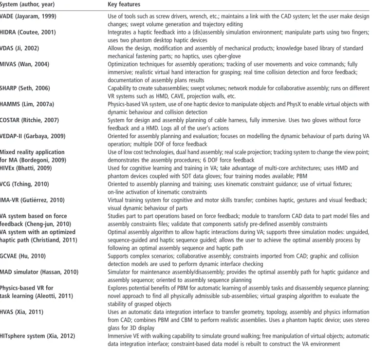
Several authors have developed VA systems using different methodologies such as automatic feature matching recognition (Iacob et al., 2011; Sato et al., 2011; Vigano and Osorio-Go´mez, 2012; Xu et al., 2012); constrained motion (Tching et al., 2010; Zaldivar-Colado and Garbaya, 2009; Gutie´rrez et al., 2010; Xia et al., 2012); reuse of CAD assembly constraints (Jayaram et al., 1999; Chamaret et al., 2010; Chen et al., 2010; Cheng-jun et al., 2010); physics-based modelling (PBM) (Garbaya and Zaldivar-Colado, 2009; Gupta et al., 1997; Aleotti and Caselli, 2011; Wan et al., 2004; Seth et al., 2006; Lim et al., 2007a); hybrid approaches (Seth, 2007; Xia et al., 2011); and the use of haptic feedback (Coutee et al., 2001; Ji et al., 2011; Christiand and Yoon, 2011; Ladeveze et al., 2010; Liu et al., 2010; Bordegoni et al., 2009; Lim et al., 2007a, b). A brief description of the main characteristics of these platforms is presented in Table I.
2.2 Force feedback importance
The importance of force feedback during VA process has been demonstrated by several authors, such as Gupta et al. (1997), Lim et al. (2007b) and Xia et al. (2013), who proved that the assembly time can be reduced by the use of force feedback. An evaluation of two different collision feedback modalities, visual and force feedback, for VA verification was carried out by Sagardia et al. (2012). The results revealed a clear and highly significant superiority of force over visual feedback.
According to Xia et al. (2013), haptics improves the VA performance by reducing completion time, increasing the accuracy to position virtual objects and guiding steadier hand motions along 3D trajectories.
2.3 Key aspects of VA
Four main applications of VA are identified:
1 path planning and optimisation for robotic or human assembly task;
2 design for assembly analysis;
3 maintenance analysis and evaluation; and 4 assembly training.
According to Zhu et al. (2010), the general steps of virtual assembly process planning (VAPP) are: product CAD modelling, interactive VA, automatic generation of a standard assembly process plan based on knowledge and, finally, the assembly plan to be used in the real process. The key activity related to VAPP is the interactive assembly.
The works reported in the literature have revealed that interactive VA can be used as a tool to reduce the DFM/A cycle time. Various techniques and systems have been developed
to perform VA. HAMS has been developed as a VA platform to analyse methodologies and algorithms used in VA.
3. System description
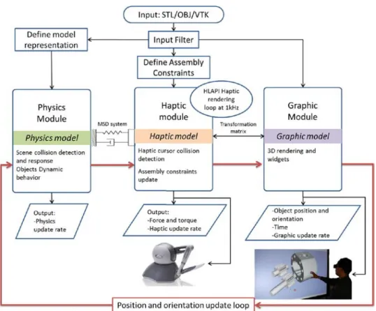
HAMS comprises three main modules: physics, haptics and graphics modules, Figure 1. The key features and characteristics of HAMS are described in the following paragraphs.
3.1 Integration
The three main modules of HAMS have been integrated using Microsoft Foundation Classes (MFC) of Visual Studio 2010. The virtual scene 3D rendering is carried out by the graphics module using the Visualization Toolkit libraries (VTK 5.10). This module is responsible of creating the virtual scene and rendering all the objects and information needed in the virtual world.
The physics module enables physical based behaviour of virtual objects. This module uses three physics simulation engines (PSEs): Bullet, PhysX v2.8 and PhysX v3.1. The user is able to select any of them during the system operation.
Finally, the haptic module provides the force feedback to enable the sense of touch and kinaesthesia for the user to recognize and manipulate virtual objects. HLAPI from OpenHaptics (v3.0) is used for haptic rendering. Dual haptic interaction is possible via a pair of Phantom Omni haptic devices (Figure 2).
3.2 Model creation
In HAMS virtual objects are imported as STL, OBJ or VTK file formats. An object unique identifier (ID) and material are assigned to each virtual object. The user can select from four different materials: lead, steel, wood or plastic, each with different density. The triangular mesh data describing an object is used to create three different models: the graphics, the physics and the haptics models.
To create the graphics model, a triangle mesh mapper fits the data in such a way that it can be rendered graphically by using the VTK commands. The physics model is required by the PSE for collision detection and dynamic behaviour of virtual objects; it is invisible to the user and can be vastly different from the graphic model. However, for assembly purposes, the physics model must be as geometrically accurate as the graphic model (Gonzalez et al., 2012). The algorithms used in HAMS to generate the collision shape (physics model) from a triangular mesh are listed in Table II.
Finally, for haptic rendering, HAMS uses the higher level graphics attributed methods (HLAPI) from OpenHaptics. HLAPI captures the geometry specified by VTK-OpenGL commands (graphic model) and uses it to perform haptic rendering of virtual objects (haptic model).
3.3 Haptic manipulation and force feedback
During the simulation of the assembly process HAMS has three user motion modalities:
1 the wander; 2 the touch; and 3 the control modes.
Wandering refers to the user’s movements around the virtual scene but without touching or manipulating any object. The touching mode is activated when the user touches an object with the haptic device to explore its shape by force feedback.
In the controlling mode the objects are manipulated by the user through the haptic devices. The movements of the manipulated objects are created as follows:
. The haptic shape is coupled to the physics model trough a
mass-spring-damper (MSD) system defined as:
m€x¼ 2kx 2 c_x ð1Þ
. The haptic model is moved directly by the position and
orientation of the haptic device.
. When the haptic model changes its position, a forceðm€xÞ
is computed using the MSD system.
. The resulting force is then applied to the physics model,
producing its movement.
. Finally, the graphics model is updated through a
transformation matrix using the position and orientation of the physics model (Figure 3).
3.4 Assembly methodology
According to Xia et al. (2013) and Seth et al. (2011), the two most common methodologies to model an assembly process in VEs are: PBM and constraint-based modelling (CBM). In PBM, the virtual objects are dynamic and interact with each other by means of collision response, resulting in a physics behaviour similar to the real world. The contact response between objects prevents the overlapping of virtual objects, enabling the assembly of components (Figure 4). HAMS relies on the PSE to enable PBM in virtual assemblies. Table I Key features of some VA platforms
System (author, year) Key features
VADE (Jayaram, 1999) Use of tools such as screw drivers, wrench, etc.; maintains a link with the CAD system; let the user make design changes; swept volume generation and trajectory editing
HIDRA (Coutee, 2001) Integrates a haptic feedback into a (dis)assembly simulation environment; manipulate parts using two fingers; uses two phantom desktop haptic devices
VDAS (Ji, 2002) Allows the design, modification and assembly of mechanical products; knowledge based library of standard mechanical fastening parts; no haptics, uses cyber-glove
MIVAS (Wan, 2004) Optimization techniques for assembly operations; tracking of user movements and voice commands; fully immersive; realistic virtual hand interaction for grasping; real time collision detection and force feedback; documentation of assembly plans results
SHARP (Seth, 2006) Capability to create subassemblies; swept volumes; network module for collaborative assembly; runs on different VR systems such as HMD, CAVE, projection walls, etc.
HAMMS (Lim, 2007a) Physics-based VA system, use of one haptic device to manipulate objects and PhysX to enable virtual objects with dynamic behaviour and collision detection
COSTAR (Ritchie, 2007) System for design and assembly planning of cable harness, fully immersive. Uses two gloves without force feedback and a HMD. Logs all of the user’s actions
VEDAP-II (Garbaya, 2009) Oriented for assembly planning and evaluation; focuses on modelling the dynamic behaviour of parts during VA operation; multiple DOF of force feedback
Mixed reality application for MA (Bordegoni, 2009)
Use of low cost technologies, dual hand assembly; real scale projection; tracking system to change the view point; demonstrates the assembly procedures; 6 DOF force feedback
HIVEx (Bhatti, 2009) Used for cognitive learning and training in VA; take advantage of multi-core architectures; uses HMD and phantom devices coupled with 5DT data gloves; four training modes available; PBM
VCG (Tching, 2010) Oriented to assembly planning and training; uses kinematic constraint guidance; use of virtual fixtures; on-line activation of kinematic constraints
IMA-VR (Gutie´rrez, 2010) Virtual training system for cognitive and motor skills transfer; combines haptic, gestures and visual feedback; visual dynamic behaviour of parts
VA system based on force feedback (Cheng-jun, 2010)
Studies part to part operations based on force feedback; module to transform CAD data to part model files and assembly constraints files; validate that components satisfy pre-defined assembly constraints
VA system with an optimized haptic path (Christiand, 2011)
Optimal assembly algorithm to allow haptic interactions during VA; supports three simulation modes: unguided, sequence-guided and haptic sequence guided; allows the user to achieve the optimal assembly process by following an optimal assembly sequence and haptic path
GCVAE (Hu, 2010) Supports complex scenarios; collaborative assembly; constraints imported from CAD; graphic and collision detection models are used to perform dynamic interface checking
MAD simulator (Hassan, 2010) Simulator for maintenance assembly/disassembly; provides the optimal assembly path for haptic guidance and assembly sequence; oriented to assembly sequence planning
Physics-based VR for task learning (Aleotti, 2011)
Explores potential benefits of PBM for automatic learning of assembly tasks and disassembly sequence planning; novel approach to find all physically admissible sub-assemblies; virtual grasping algorithm to evaluate the stability of grasped objects
HVAS (Xia, 2011) Uses an automatic data integration interface to transfer geometry, topology, assembly and physics information from CAD; combines PBM and CBM to perform realistic assemblies. Uses a phantom haptic device; uses stereo glass for 3D display
HITsphere system (Xia, 2012) Immersive VE with walking capability to simulate ground walking; free manipulation of virtual objects; automatic data integration interface; constraint-based data model is rebuilt to construct the VA environment
However, PBM has the disadvantage of high computational cost, particularly for non-convex objects, caused by the complexity of computing collisions among such objects.
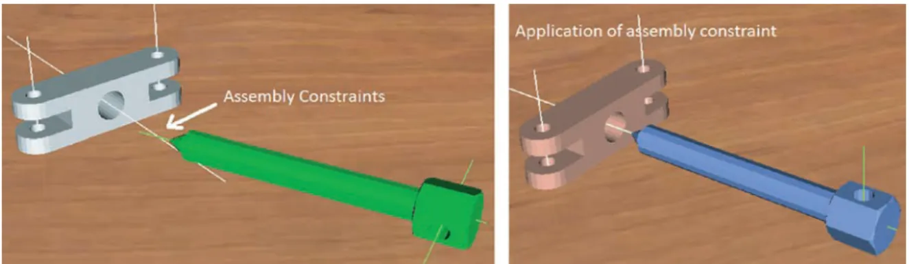
In CBM the assembly is performed by reducing the degrees of freedom (DOF) of the manipulated object relative to the final assembly position, resulting in a motion constrained part (Figure 5). This methodology has the advantage of low computational cost. When CBM is integrated into a PBM system it is possible to improve its performance and at the same time maintain the realism and intuitive behaviour. In order
to improve the performance of VA, dynamic assembly constraints (DAC) have been developed and implemented in HAMS. DAC helps to reduce the computing load of collision detection during the assembly and it also aids the user to reach the final assembly position and orientation of the manipulated part.
3.5 Dynamic assembly constraints
Two types of assembly constraints have been developed and implemented in HAMS:
Figure 1 HAMS architecture
1 Cylindrical constraints, which are applied to cylindrical features of objects (Figure 4). When this type of constraint is active, the manipulated object can only rotate or translate along the constraint axis.
2 Planar constraints, which are defined by planar faces of an object. When this constraint is active the manipulated part can only move or rotate on the constraint plane.
In order to use constraints during the VA process, it is required to define a base part where the rest of the parts, named as “manipulated parts”, will be assembled. The assembly
constraints of the manipulated parts and the base part must be defined previously.
3.5.1 Assembly constraints definition
DACs can be automatically or manually defined as described in the following paragraphs.
(a) Automatic definition of cylindrical assembly constraints. Cylindrical features of a model can be recognized by analysing the object’s edges. An edge is composed of two indices: A and B. A closed edge is identified when the index A of the first analysed edge and the index B of the last analysed edge are the same. If a closed edge is identified then its size is analysed Figure 4 Physics-based modelling operation
Figure 3 Manipulation of virtual objects Table II Model representation algorithms in PSE’s
PSE Algorithm Description
Bullet Convex The object is represented as a convex object (a wrapped object)
HACD (Mamou and Ghorbel, 2009) Hierarchical approximate convex decomposition, the object is decomposed in smaller convex objects GIMPACT (GIMPACT, 2011) Uses triangular mesh to perform collision detection
PhysX v2.8 and v3.x
Convex The object is represented as a convex object (a wrapped object)
ACD Approximate convex decomposition, the object is decomposed in smaller convex objects
HACD (Mamou and Ghorbel, 2009) Hierarchical approximate convex decomposition, the object is decomposed in smaller convex objects ConvexFT (Gonzalezet al., 2012) ConvexFromTriangle, creates one convex object for each triangle of the triangular mesh
in the three coordinate axes. If two dimensions are similar, within a pre-defined tolerance, then a circular feature has been found and is defined by its diameter, centre and orientation.
Once all the circular features of a model have been identified, a second analysis is performed to find if two circles have the same position and orientation. If this happens, a cylindrical feature has been recognized and its position, depth and orientation are used to define a new cylindrical assembly constraint. Table III presents the results when applying the algorithm to the objects shown in Figure 6.
(b) Manual definition of cylindrical assembly constraints. Cylindrical constraints that are not automatically recognized by the previous algorithm can be manually defined by selecting four points on the cylindrical feature using the haptic device. The first three points must be selected on one edge of the cylindrical feature to compute the centre of the cylinder and the fourth point must be selected on the opposite face of the cylindrical feature to compute the depth and orientation. The assembly constraints are saved as a text file in order to be used whenever the model is loaded.
(c) Manual definition of planar assembly constraints. A planar constraint is defined by selecting four points on a face of the model; these points define the plane where the
assembly constraint is intended to be applied. The manually defined planar constraints are also saved as a text file. 3.5.2 Application of assembly constraints
When a virtual object is manipulated by the haptic device, it moves freely. However, when the manipulated object approaches the base part the system evaluates if any assembly constraint is close enough to a similar constraint of the base part. If one pair of constraints is coincident the DAC is activated, the manipulated part is then reoriented and located according to the base part constraint. The DOF of the manipulated part are then reduced according to the type of constraint.
When a manipulated part is released at the desired position and the DAC is active, a kinematic joint between the manipulated part and the base part is created, allowing the creation of subassemblies.
3.6 Data logging
The data generated during the VA process is logged for further processing. HAMS uses three modules for data logging:
1 in the first module the object position, orientation, trajectories, name, haptic cursor position and time are logged;
Figure 5 Constraint-based modelling operation
Figure 6 Automatic cylindrical feature recognition evaluated parts
(a) (b) (c) (d)
Notes: (a) Puller base; (b) pump housing; (c) valve throttle; (d) valve housing Table III Results of the automatic assembly constrain definition algorithm
Object Original cylindrical features Detected cylindrical features
Bearing puller base 5 5
Oil pump housing 26 24
Valve throttle 3 3
2 in the second module the torques and forces applied to manipulated objects are logged; and
3 the third module logs the system performance parameters such as haptics, physics and graphics update rates. Each module logs the information during each simulation step. Once the assembly is completed the logged data can be saved as a *.txt or *.csv file format.
(a) Chronocyclegraphs
A method to visualize the logged data is the use of chronocyclegraphs (Lim et al., 2007b; Ritchie et al., 2008; Lim et al., 2010), which are graphic representations of the trajectories followed by the user when manipulating the haptic device. The user movements are symbolized by coloured spheres which represent the modality of the VA (Table IV), with the distance between spheres representing the speed of the movement.
3.7 System increased functionality
HAMS offers different functions that provide increased flexibility and robustness to the system:
. Multimodal graphic rendering that allows the
modification of the object rendering type, i.e. the virtual object can be rendered as solid, transparent, invisible, by points, by edges, by wireframe or textured. Another functions includes full camera manipulation around the virtual scene (pan, zoom and rotate), and pre-defined camera viewpoints (front, rear, top, left, right and isometric).
. A haptic properties control panel that includes options to
enable or disable the haptic device, select a haptic rendering method or modify the haptic cursor size. In this panel haptic properties such as stiffness, damping, static and dynamic friction can be modified. DAC can be also defined, modified and activated in this panel.
. A physics properties control panel that allows the
modification during run-time of physics simulation parameters such as mass, collision shape tolerance, restitution, gravity, friction, simulation time step and PSE selection.
. DACs parameters can be modified through the use of
widgets, Figure 7. These widgets can be manipulated via the mouse or the haptic device.
4. System evaluation
Four VA tasks were selected to evaluate the functionality of HAMS, Table V. In order to minimize the complexity of the assembly process, these tasks were performed using one haptic device (one hand configuration). Due to its stability and performance in a preliminary evaluation, Bullet was selected as
the PSE (Gonzalez-Badillo et al., 2012). The real assembly of the components was also carried to compare the real and virtual task completion times (TCT). The real objects were manufactured using rapid prototyping techniques in order to create objects with the same features and tolerances than virtual objects. At least five trials were carried out for each assembly tasks (virtual and real).
4.1 Bearing puller
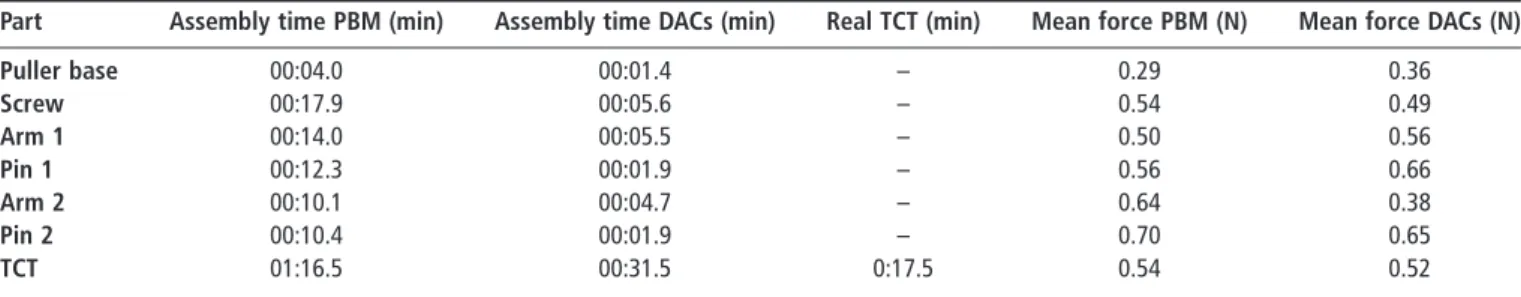
The disassembled bearing puller is shown in Figure 8(a). The VA of this component was carried out without DACs (Figure 8(b)) and with DACs (Figure 8(c)). The task is completed when the last pin is assembled (Figure 8(d)). During the assembly the base part remained static whilst the rest of the objects were dynamic. The chronocyclegraphs corresponding to the assembly of this component are shown in Figure 8(e). The same assembly procedure was carried out with the real parts (Figure 8(f)).
The results of the bearing puller assembly are summarized in Table VI. From these results it is observed that the use of DACs drastically reduce the assembly time and the TCT. The mean haptic force feedback rendered to the user is also presented in Table VI, where it can be observed that force feedback is similar when using PBM and DACs.
4.2 Gear oil pump
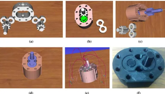
The disassembled parts of the gear oil pump are shown in Figure 9(a). The VA was carried out without DACs (only using PBM) (Figure 9(b)) and with DACs (Figure 9(c)). The task is completed when the top bearing is assembled (Figure 9(d)). During the assembly the housing remained static whilst the rest of the objects were dynamic. The chronocyclegraphs of this task are shown in Figure 9(e). The same assembly task was carried out with the real parts (Figure 9(f)).
Table VII shows the results of the gear oil pump assembly. Similarly to the bearing puller assembly, the TCT and individual assembly times are smaller and closer to the Figure 7 Widgets used to modify DACs properties
Table IV Graphic representation of user movements
Spheres Modality
Green Wandering mode, scene recognizing Blue Touching mode, virtual object recognizing Red Controlling mode, virtual object manipulation
real assembly when DACs are used. The force rendered to the user during the assembly of the large gear without DACs is shown in Figure 10(a), whilst the assembly force when using DACs is shown in Figure 10(b). From these results it is observed that when DACs are used, the forces rendered to the user are smaller and more stable.
Figure 11 shows the graphics, physics and haptics simulation update times corresponding to the gear oil pump assembly task. It can be observed that haptics and graphics simulation times tend to remain constant during the whole assembly process. However, the physics simulation time increases with the assembly progress; this is caused by the increment of contact points needed for collision detection in each simulation step. It is also observed that the physics simulation time is smaller when DACs are used.
4.3 Pneumatic cylinder
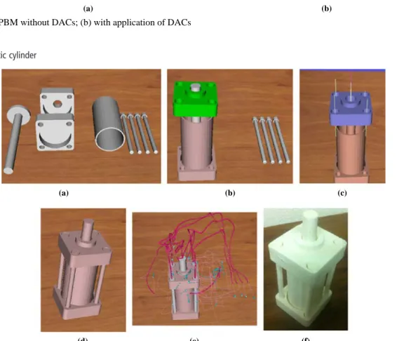
The parts used in this assembly are shown in Figure 12(a). The VA was carried out without DACs (Figure 12(b)) and with DACs (Figure 12(c)). The task is completed when the forth screw is assembled (Figure 12(d)). The rear cap, cylinder and front cap remained static once assembled, whilst the screws and plunger were dynamic. The chronocyclegraphs corresponding to this assembly tasks are shown in Figure 12(e). The same assembly task was carried out with the real parts (Figure 12(f)).
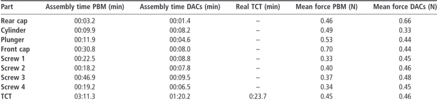
The results of the pneumatic cylinder assembly are summarized in Table VIII. Similarly to the previous assembly tasks, the individual assembly time and TCT are smaller when using DACs. On the other hand, the mean force feedback is similar for both cases (PBM and DACs). Figure 8 Bearing pump assembly
(a) (b) (c)
(d) (e) (f)
Notes: (a) Virtual objects; (b) HAMS assembly using only PBM; (c) HAMS assembly using DACs;
(d) HAMMS assembly; (e) assembly chronocyclegraphs; (f) real assembly
Table VI Results of the bearing puller assembly
Part Assembly time PBM (min) Assembly time DACs (min) Real TCT (min) Mean force PBM (N) Mean force DACs (N)
Puller base 00:04.0 00:01.4 – 0.29 0.36 Screw 00:17.9 00:05.6 – 0.54 0.49 Arm 1 00:14.0 00:05.5 – 0.50 0.56 Pin 1 00:12.3 00:01.9 – 0.56 0.66 Arm 2 00:10.1 00:04.7 – 0.64 0.38 Pin 2 00:10.4 00:01.9 – 0.70 0.65 TCT 01:16.5 00:31.5 0:17.5 0.54 0.52
Table V Assembly cases and sequences performed to evaluate HAMS Component Base part Assembly sequence
Bearing puller Puller base Puller base (static) ! screw 1 ! arm 1 ! pin 1 ! arm 2 ! pin 2
Gear oil pump Housing Housing (static) ! bottom bearing ! large gear ! short gear ! top bearing
Pneumatic cylinder Rear cap Rear cap (static) ! cylinder ! plunger ! front cap ! screw 1 ! screw 2 ! screw 3 ! screw 4 Bench vice Large jaw Large jaw (static) ! short jaw (static) ! screw ! pin
Figure 9 Oil pump assembly
(a) (b) (c)
(d) (e) (f)
Notes: (a) Virtual objects; (b) HAMS assembly using only physics object; (c) HAMS assembly using
DACs; (d) HAMMS assembly; (e) assembly chronocyclegraphs; (f) real assembly
Figure 10 Logged force when manipulating and assembling the large gear
(a) (b)
Notes: (a) PBM without DACs; (b) with application of DACs Table VII Results of the gear oil pump assembly
Part Assembly time PBM (min) Assembly time DACs (min) Real TCT (min) Mean force PBM (N) Mean force DACs (N)
Housing 0:05.2 0:01.9 – 0.27 0.25 Bottom bearing 0:15.0 0:07.5 – 0.68 0.32 Large gear 0:13.5 0:04.0 – 0.62 0.47 Short gear 0:31.0 0:07.8 – 0.78 0.34 Top bearing 0:11.4 0:09.7 – 0.88 0.35 TCT 1:29.3 0:41.7 0:13.1 0.65 0.35
4.4 Manual bench vice
The disassembled bench vice is shown in Figure 13(a). The VA of the bearing puller was carried out using only the PBM (Figure 13(b)). The task is completed when the pin is assembled (Figure 13(c)). The objects remained static after being assembled. The chronocyclegraphs of this assembly are shown in Figure 13(d). The real assembly was also performed, Figure 13(e). Table IX summarizes the results of the bench vice assembly. The results show that virtual TCT is greater than real TCT as it was expected.
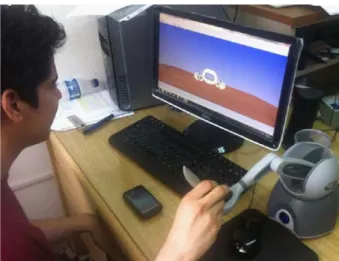
4.5 User perception
In order to validate the system functionality, a set of experiments was carried out by several users, which were asked to perform the gear oil pump assembly following a specific order, Figure 14. First, all the users were trained in the system during 20 min to minimize learning effects. When using only PBM, a mean TCT of 3:29.4 min with a standard deviation of 57.8 s was obtained. When using DACs, a mean TCT of 2:20.7 min with a standard deviation of 31.0 s was measured. It can be observed that the use of DACs enhance the VA process by reducing the TCT. Figure 11 Logged simulation time when assembling the oil gear pump
(a) (b)
Notes: (a) PBM without DACs; (b) with application of DACs
Figure 12 Pneumatic cylinder
(a) (b)
(d) (e) (f)
(c)
Notes: (a) Virtual objects; (b) HAMS assembly using only physics object; (c) HAMS assembly using
The users were asked to qualitatively evaluate the system and the VA experience by assigning values to the following parameters:
. Ease of controlling the haptic device, from 0 if controlling
the device was very difficult, to 4 if it was very easy and comfortable.
. Ease of performing the VA, from 0 if the assembly process
was very difficult, to 4 if the process was very easy.
. Virtual objects stability, from 0 if the virtual objects were
jumping or flying in the scene, to 3 if the objects were very stable.
. Realism of the process, from 0 if virtual objects behaviour
is far from real objects, to 3 if virtual objects behave like real objects.
. Collision feedback, from 0 if the collision feedback
through the haptic device is not perceptible, to 3 if all the collisions of manipulated objects are accurately rendered by the haptic device.
. TCT perception, from 0 if the user perceived VA TCT to
be larger than real TCT, to 3 if virtual TCT is perceived to be smaller than real TCT.
The results of the user’s qualitative evaluation are shown in Figure 15. It can be observed that collision feedback is the best evaluated parameter, which means that collisions are accurately rendered by means of the haptic device. The TCT of the VA is perceived to be larger than the TCTof the real assembly, which is confirmed by the experimental measurements. The rest of the Figure 13 Manual bench vice assembly
(a) (b) (c)
(d) (e)
Notes: (a) Virtual objects; (b) HAMS assembly using physics object; (c) HAMMS assembly;
(e) assembly chronocyclegraphs; (f) real assembly
Table VIII Results of the pneumatic cylinder assembly
Part Assembly time PBM (min) Assembly time DACs (min) Real TCT (min) Mean force PBM (N) Mean force DACs (N)
Rear cap 00:03.2 00:01.4 – 0.46 0.66 Cylinder 00:09.9 00:08.2 – 0.49 0.33 Plunger 00:11.9 00:04.6 – 0.53 0.44 Front cap 00:30.8 00:08.0 – 0.70 0.44 Screw 1 00:22.5 00:08.8 – 0.33 0.45 Screw 2 00:18.2 00:07.8 – 0.40 0.46 Screw 3 00:46.9 00:09.5 – 0.37 0.48 Screw 4 00:19.2 00:06.5 – 0.34 0.45 TCT 03:11.3 01:20.2 0:23.7 0.45 0.46
Table IX Results of the bench vice assembly
Part Assembly time PBM (min) Real TCT (min) Mean force PBM (N)
Large jaw 00:03.4 – 0.25
Short jaw 00:24.1 – 0.61
Screw 00:23.2 – 0.46
Pin 00:13.5 – 0.25
qualitative parameters have a satisfactory evaluation, which means that users have a good overall perception of HAMS.
Regarding the overall perception of HAMS, most of the users considered that:
. they felt confident while doing the VA; . the system is useful and interesting;
. the virtual objects move according with the movements of
the hand; and
. virtual objects have a good accuracy respect to collision
response.
Finally, the users suggested that the simulation process must be faster and the haptic interaction must be improved by using haptic devices with more DOF and contact points, e.g. a haptic glove.
5. Discussion
The key features of HAMS and other haptic VA systems proposed by different authors are presented in Table X. It can be observed that HAMS includes several characteristics that make it different from similar systems. One of the outstanding characteristic is a hybrid approach (PBM and CBM) to perform the assembly process with DACs that can be manually or
automatically created. Unlike similar systems, HAMS is the only system where the user can manipulate the camera viewpoint using the haptic device, i.e. without the need to release the device and use the mouse or keyboard to perform this operation. Another important feature of HAMS is the possibility to automatically create a subassembly without the need of manually updating parameters such mass, inertia, etc. The subassembly is automatically created once the manipulated part is assembled in the target position.
6. Conclusions
A new HAMS has been presented and described. The system comprises three main modules: haptics, graphics and physics. The outstanding characteristics of HAMS are: the use of DACs to enhance the VA process; automatic or manual definition of assembly constraints within the VA system; control panels and widgets to modify simulation parameters during run-time; assembly data logging, different collision shape representation algorithms and the possibility to select the PSE to perform the VA. These characteristics make HAMS a complete, flexible and robust VA platform for planning, evaluation, simulation and training of assembly tasks in a more natural and intuitive way. Figure 15 Results of the qualitative evaluation of the system using PBM without DACs (PBM) and using DACs (DAC)
The case studies have proved the effectiveness and functionality of HAMS to perform haptic VA process of any object previously designed in a CAD system and exported as STL, OBJ or VTK format file. Also, the results have shown that in the VE the TCT is greater than the corresponding real assembly TCT. However, the results obtained in the multi-users tests have probed that the use of DACs can reduce the virtual TCT.
Future work considers the evaluation of the algorithm used to create the collision shape, and the effect of using different PSEs on the VA performance. The evaluation of HAMS as a tool for assembly planning and training is also considered as part of the future work.
References
Aleotti, J. and Caselli, S. (2011), “Physics-based virtual reality for task learning and intelligent disassembly planning”, Virtual Reality, Vol. 15, pp. 41-54.
Bhatti, A., Nahavandi, S., Khoo, Y.B., Creighton, D., Anticev, J. and Zhou, M. (2009), “Haptically enable interactive virtual assembly training system development and evaluation”, SIMTECT 2009: Proceedings of the 2009 International Design Engineering Technical Conferences & Computers and Information in Engineering Conference, Adelaide, South Australia, pp. 1-6.
Boothroyd, G. (1992), Assembly Automation and Product Design, Marcel Dekker, New York, NY.
Bordegoni, M., Cugini, U., Belluco, P. and Aliverti, M. (2009), “Evaluation of a haptic-based interaction system for virtual manual assembly”, Virtual and Mixed Reality, LNCS 5622, Springer, Berlin, pp. 303-312.
Chamaret, D., Ullah, S. and Naud, P.M.R. (2010), “Integration and evaluation of haptic feedbacks: from CAD models to virtual prototyping”, Int. J. Interact. Des. Manuf., Vol. 4, pp. 87-94.
Chen, C.J., Ong, S.K., Nee, A.Y.C. and Zhou, Y.Q. (2010), “Haptic-based interactive path planning for a virtual robot arm”, Int. J. Interact. Des. Manuf., Vol. 4, pp. 113-123. Table X Comparative of HAMS with similar VA systems
Features HAMS SHARP (Sethet al., 2006) HVAS (Xiaet al., 2011) HIVEx (Bhatti et al., 2009) HIDRA (Coutee et al., 2001) End purpose Training, path planning,
assembly evaluation and simulation analysis
Path planning and assembly evaluation Path planning and assembly evaluation Cognitive learning and training
Assembly and path planning
Assembly modelling technique
PBM and CBM (hybrid) PBM and CBM (hybrid) PBM and CBM (hybrid)
PBM PBM and limited CBM Method used
to create assembly constraints
Manual and automatic based on model features
Manual and automatic Form CAD assembly constraints
Not supported Manually defined only in orthogonal axis Logged data Manipulated part position,
orientation, time, force, torque and simulation update rates
Record and play module Positions, forces and torques
Completion time and percentage of correct parts selected Not mentioned Visualization of resulting assembly path
Chronocyclegraphs Swept volumes Discrete points or swept volumes
For demonstration purposes
Not supported
Dual handed haptic device configuration
Supported Supported Not supported One handed, data glove attached to phantom
Dual haptics but only one hand manipulation
Import of CAD models
Geometry imported using STL, OBJ and VTK file formats Geometry imported using voxel models or B-Rep Automatic data integration interface VRLM, geometry, assembly and physical data
Import geometry using VRLM format file Method to create
the collision shape
Trimesh, convex decomposition, convex elements and primitives
B-Rep, VPS Convex decomposition
Smart collision Convex decomposition Complex models Supported Supported Supported Supported Primitives or convex
elements Collaborative assembly Local Supported, network
module
Not mentioned Not supported No Possibility to define
materials
Supported Not mentioned From CAD model
From CAD model Supported Full camera
manipulation
By haptic device or mouse Not mentioned Not mentioned Not mentioned By keyboard Possibility to create
subassemblies
Supported Supported, needs the redefinition of model properties
Cheng-jun, C., Yun-feng, W. and Niu, L. (2010), “Research on interaction for virtual assembly system with force feedback”, ICIC’10 Proceedings of the 2010 Third International Conference on Information and Computing, Vol. 2, pp. 147-150.
Christiand and Yoon, J. (2011), “Assembly simulations in virtual environments with optimized haptic path and sequence”, Robotics & Computer-Integrated Manufacturing, Vol. 27, pp. 306-317.
Coutee, A.S., McDermott, S.D. and Bras, B. (2001), “A haptic assembly and disassembly simulation environment and associated computational load optimization techniques”, J. of Comp. and Information Science in Engineering, Vol. 1, pp. 113-122.
Garbaya, S. and Zaldivar-Colado, U. (2009), “Modeling dynamic behavior of parts in virtual assembly environment”, Proceedings of the ASME/AFM 2009 World Conference on Innovative Virtual Reality, Chalon-sur-Saoˆne, France.
GIMPACT (2011), “GIMPACT, geometric tools for VR”, available at: http://gimpact.sourceforge.net/reference_html/ features.html (accessed 3 January 2014).
Gonzalez, G., Medellin, H.I., Lim, T. and Ritchie, J.M. (2012), “3D object representation for physics simulation engines and its effect on virtual assembly tasks”, Proceedings of the ASME 2012 IDETC/CIE, Chicago, IL, 12-15 August. Gonzalez-Badillo, G., Medellı´n-Castillo, H.I., Fletcher, C., Lim, T., Ritchie, J.M. and Garbaya, S. (2012), “An evaluation of physics engines and their application in haptic virtual assembly environments”, in Hinduja, S. and Li, L. (Eds), Proceedings of the 37th International MATADOR Conference, pp. 227-230.
Gupta, R., Whitney, D. and Zeltzer, D. (1997), “Prototyping and design for assembly analysis using multimodal virtual environments”, Computer Aided Design, Vol. 29 No. 8, pp. 585-597 (special issue on VR in CAD).
Gutie´rrez, T., Barbero, J.I., Aizpitarte, M., Carrillo, A.R. and Eguidazu, A. (1998), “Assembly simulation through haptic virtual prototypes”, Proceedings of the Third PHANTOM Users Group Workshop, Cambridge, MA.
Gutie´rrez, T., Rodrı´guez, J., Ve´laz, Y., Casado, S., Suescun, A. and Sa´nchez, E.J. (2010), “IMA-VR: a multimodal virtual training system for skills transfer in industrial maintenance and assembly tasks”, paper presented at 19th IEEE Int. Symp. on Robot and Human Interactive Communication, Principe di Piemonte-Viareggio, Italy.
Hassan, S. and Yoon, J. (2010), “Haptic based optimized path planning approach to virtual maintenance assembly/ disassembly (MAD)”, paper presented at the 2010 IEEE/ RSJ Int. Conference on Intelligent Robots and Systems, Taipei, Taiwan, 18-22 October.
Hu, Y., Wu, D., Fan, X. and Zhen, X. (2010), “Grid-enabled collaborative virtual assembly environment”, Assembly Automation, Vol. 30 No. 4, pp. 352-364.
Iacob, R., Mitrouchev, P. and Le´on, J. (2011), “Assembly simulation incorporating component mobility modelling”, Int. J. Interact. Des. Manuf., Vol. 5 No. 2, pp. 119-132. Jayaram, S., Jayaram, U., Wang, Y., Tirumali, H., Lyons, K.
and Hart, P. (1999), “VADE: a virtual assembly design environment”, Computer Graphics and Applications, Vol. 19 No. 6, pp. 44-50.
Ji, J., Lee, K.M. and Zhang, S. (2011), “Cantilever snap-fit performance analysis for haptic evaluation”, Journal of Mechanical Design, ASME, Vol. 133 No. 12, pp. 1-8.
Ji, P., Choi, A.C.K. and Tu, L. (2002), “VDAS: a virtual design and assembly system in a virtual reality environment”, Assembly Automation, Vol. 22 No. 4, pp. 337-342.
Ladeveze, N., Fourquet, J. and Puel, B. (2010), “Interactive path planning for haptic assistance in assembly tasks”, Computers & Graphics, Vol. 34, pp. 17-25.
Lim, T., Ritchie, J.M., Corney, J.R., Dewar, R.G., Schmidt, K. and Bergsteiner, K. (2007a), “Assessment of a haptic virtual assembly system that uses physics-based interactions”, Proceedings of the 2007 IEEE International Symposium on Assembly and Manufacturing, Ann Arbor, MI, USA, 22-25 July, pp. 147-153.
Lim, T., Ritchie, J.M., Sung, R., Kosmadoudi, Z., Liu, Y. and Thin, A.G. (2010), “Haptic virtual reality assembly – moving towards real engineering applications”, in Zadeh, M.H. (Ed.), Advances in Haptics, available at: www.intechopen.com/books/advances-in-haptics/haptic- virtual-reality-assembly-moving-towards-real-engineering-applications (accessed 3 January 2014)
Lim, T., Ritchie, J.M., Dewar, R.G., Corney, J.R., Wilkinson, P., Calis, M., Desmulliez, M. and Fang, J.-J. (2007b), “Factors affecting user performance in haptic assembly”, Virtual Reality Special Issue, Springer, New York, NY.
Liu, M., Wang, D. and Zhang, Y. (2010), “A novel haptic rendering algorithm for stable and precise 6-dof virtual assembly”, Proceedings of the ASME 2010 World Conference on Innovative Virtual Reality, Ames, IA, USA.
Mamou, K. and Ghorbel, F. (2009), “A simple and efficient approach for 3D mesh approximate convex decomposition”, paper presented at 16th IEEE International Conference on Image Processing (ICIP’09), Cairo, 7-10 November.
Ritchie, J.M., Lim, T., Sung, R.S. and Medellin, H. (2008), “Generation of assembly process plans and associated Gilbreth motion study data”, paper presented at 2nd International Workshop Virtual Manufacturing VirMan 08 as Part of the 5th INTUITION International Conference: Virtual Reality in Industry and Society: Frome Research to Application, Torino, Italy, 6-8 October.
Ritchie, J.M., Robinson, G., Day, P.N., Dewar, R.G., Sung, R.C.W. and Simmons, J.E.L. (2007), “Cable harness design, assembly and installation planning using immersive virtual reality”, Virtual Realiy, Vol. 11, pp. 261-273.
Sagardia, M., Weber, B., Hulin, T., Hirzinger, G. and Preusche, C. (2012), “Evaluation of visual and force feedback in virtual assembly verifications”, paper presented at IEEE Virtual Reality, Costa Mesa, CA, USA, 4-8 March. Sato, K., Date, H. and Onosato, M. (2011), “Fast matching,
combinations extraction and configuration of mesh models using graph-based feature representation”, Int. J. Interact. Des. Manuf., Vol. 5, pp. 133-136.
Seth, A. (2007), “Combining physical constraints with geometric constraint-based modeling for virtual assembly”, PhD dissertation, Iowa State University, Ames, IA. Seth, A., Su, H.J. and Vance, J.M. (2006), “SHARP: a system
for haptic assembly & realistic prototyping”, paper presented at ASME Design Engineering Technical Conferences and Computers and Information in Engineering Conference, Philadelphia, PA, USA.
Seth, A., Vance, J.M. and Oliver, J.H. (2011), “Virtual reality for assembly methods prototyping: a review”, Virtual Reality, Vol. 15, pp. 5-20.
Tching, L., Dumont, G. and Perret, J. (2010), “Interactive simulation of CAD models assemblies using virtual constraint guidance”, Int. J. Interact. Des. Manuf., Vol. 4 No. 2, pp. 95-102.
Vigano, R. and Osorio-Go´mez, G. (2012), “Assembly planning with automated retrieval of assembly sequences from CAD model information”, Assembly Automation, Vol. 32 No. 4, pp. 347-360.
Wan, H., Gao, S., Peng, Q., Dai, G. and Zhang, F. (2004), “MIVAS: a multi-modal immersive virtual assembly system”, Proceedings of the ASME Design Engineering Technical Conference, Salt Lake City, UT, pp. 113-122.
Xia, P., Lopes, A.M. and Restivo, M.T. (2011), “Design and implementation of a haptic-based virtual assembly system”, Assembly Automation, Vol. 31 No. 4, pp. 369-384.
Xia, P., Lopes, A.M. and Restivo, M.T. (2013), “A review of virtual reality and haptics for product assembly (part 1): rigid parts”, Assembly Automation, Vol. 33 No. 1, pp. 68-77. Xia, P., Lopes, A.M., Restivo, M.T. and Yao, Y. (2012), “A new type haptics-based virtual environment system for
assembly training of complex products”, Int. Journal of Advanced Manufacturing Technology, Vol. 58 Nos 1/4, pp. 379-396.
Xu, L.D., Wang, C., Bi, Z. and Yu, J. (2012), “AutoAssem: an automated assembly planning system for complex products”, IEEE Transactions on Industrial Informatics, Vol. 8 No. 3. Zaldivar-Colado, U. and Garbaya, S. (2009), “Virtual
assembly environment modelling”, Proceedings of the ASME/AFM 2009 World Conference on Innovative Virtual Reality WINVR2009, Chalon-sur-Saoˆne, France, 25-26 February.
Zhu, H., Wu, D. and Fan, X. (2010), “Assembly semantics modeling for assembling process planning in virtual environment”, Assembly Automation, Vol. 30 No. 3, pp. 257-267.
Corresponding author
Germanico Gonzalez-Badillocan be contacted at: germanico. [email protected]