Université du Québec
Institut National de la Recherche Scientifique
Énergie Matériaux Télécommunications
Reconfigurable Antennas using Frequency Selective Surfaces
By
Jinxin Li
A dissertation submitted in partial fulfillment of the requirements for the degree of Doctor of Philosophy (Ph. D.) in Telecommunications
Jury d’évaluation
External examiner Prof. Cevdet Akyel
École Polytechnique de Montréal External examiner Prof. Chan-Wang Park
Université de Québec à Rimouski (UQAR)
Internal examiner Prof. Serioja O. Tatu INRS-EMT
Research Director Prof. Tayeb A. Denidni INRS-EMT
Research co-director Prof. Qingsheng Zeng
Nanjing University of Aeronautics and Astronautics
ACKNOWLEDGEMENT
First and foremost, I would like to express my sincere and profound gratitude to my supervisor Prof. Tayeb A. Denidni for his support, help and continuous encouragement throughout my PhD period. I really appreciate his continual guidance, profound insights and helpful suggestions on my research, which have been very important factor for the completion of my work.
I would like to pass my sincere thanks to my co-supervisor Dr. Qingsheng Zeng for his help and useful advices during my research endeavour.
I also gratefully thank all technical colleagues at Institute National de la Recherche Scientifique─Énergie, Matériaux et Télécommunications (INRS-EMT) and Poly-Grames Research Center for their generous help with the fabrication of my antenna prototypes. Special thanks go to my colleagues Arun Kesavan, Javad Pourahmadazar, Abdolmehdi Dadgarpour, Behnam Zarghooni, Zhenjiang Zhao and Mohamad Mantash.
The most and for most, my biggest and deepest appreciations go to my mother and my father for their encouragement, understanding and all their continuous unforgettable support during whole of my study, which gave me all the strength needed to successfully finish my PhD career. Last but not the least, I would like to thank my boyfriend for his kind care, patience, encouragement and support through the period of time.
ABSTRACT
Nowadays, because of the requirements of miniaturization and multifunction in the modern communication systems, more and more electronic devices are integrated into a single platform. By using this method, the communication quality can be improved significantly. However, another serious problem of interference has been introduced. As a solution for resolving this issue to enhance the performance of communication systems, radiation pattern reconfigurable antennas have received much attention. The conventional methods for designing radiation pattern reconfigurable antennas based on the phased antenna arrays incur large loss, and are complicated and expensive to be applied in practice. For this issues, frequency selective surfaces (FSSs) work as space filters to electromagnetic (EM) waves, which can be either transmitted or reflected in the operating frequency band. Therefore, radiation pattern reconfigurable antennas are realized by using frequency selective surface (FSS) in this thesis. This approach offers more antenna functionality, less cost and a significant save in terms of size and space. Thus, research in this field is very important and is one of the most popular fields nowadays.
In this dissertation, first and foremost, a novel dual-band beam-sweeping antenna based on two independent cylindrical active frequency selective surfaces (AFSS) have been proposed. As the AFSS unit cell characteristic is the primary influential parameter that affects the sweeping radiation pattern functionality. Hence, two AFSS unit-cells with integrated pin-diodes have been proposed at two different frequency bands, 2.45 GHz and 5.2 GHz. When a dual-band omnidirectional monopole antenna is surrounded by two cylindrical AFSS screens, the proposed design has shown that it can effectively realize beam-sweeping which covers all azimuth angles at 2.45 GHz and 5.2 GHz simultaneously. The size of antenna system can be reduced greatly in comparison with the case where the two cylindrical FSS screens work independently from each other when they are loaded in the same antenna system.
Secondly, a beam-switching antenna with high gain and flexible control of beam numbers has been proposed based on FSS. The proposed antenna is composed of an omnidirectional monopole antenna as a radiating source surrounded by a hexagon FSS screen and six metallic sheets. By changing the states of the pin-diodes in the hexagon FSS screen, the proposed antenna can not only sweep the beam six directions with gain enhancement in the azimuth plane, but also
Then, a beam-tilting antenna with negative refractive index metamaterial (NRIM) loading has also been designed. The proposed antenna is composed of a double-feed dielectric resonator antenna (DRA) and 1×4 NRIM array, which is fixed over and in the middle of the DRA. This beam-tilting antenna can steer the main beam by ±38o in the xoz-plane over 5 to 5.5 GHz band.
The reflection coefficient of the antenna is better than -10 dB in the band from 5 to 5.5 GHz. In the final design, a three layers quasi-yagi antenna has been designed with multi- beam directions in both elevation and azimuth plane at 5.2 GHz. There are four elements of quasi-Yagi antenna and eight pin-diodes as switches inserted them in the middle layer. The top and bottom layers include the parasitic elements each of which are inserted into pin-diodes. By controlling the pin-diodes in the different layers, the antenna can realize beam switching in the azimuth plane in four directions and beam tilting in the elevation plane.
TABLE OF CONTENTS
1 INTRODUCTION ... 1
1.1 BACKGROUND AND MOTIVATION ... 1
1.2 RESEARCH STATUS OF RADIATION PATTERN RECONFIGURABLE ANTENNA... 3
1.2.1 Mechanical controlling method ... 3
1.2.2 Electrical controlling method ... 4
1.2.3 Optical controlling method ... 7
1.2.4 Changing the material properties method ... 8
1.2.5 Using metamaterial method ... 9
1.3 RESEARCH OBJECTIVES ... 12
1.4 ORGANIZATION OF THE THESIS ... 12
1.5 LIST OF PUBLICATIONS ... 15
2 FREQUENCY SELECTIVE SURFACES... 17
2.1 APPLICATIONS OF FREQUENCY SELECTIVE SURFACES ... 18
2.2 DESIGN PARAMETERS FOR FREQUENCY SELECTIVE SURFACES ... 19
2.3 RESEARCH STATES OF ACTIVE FREQUENCY SELECTIVE SURFACES ... 20
2.4 INTRODUCTION OF THEORETICAL ANALYSIS METHODS OF FSS ... 22
3 DESIGN OF A DUAL-BAND BEAM SWEEPING ANTENNA USING ACTIVE SURFACE SELECTIVE SURFACES ... 23
3.1 INTRODUCTION ... 23
3.2 ACTIVE FRQUENCY SELECTIVE SURFACES UNIT CELL DESIGN ... 24
3.3 DESIGN AND OPERATION MECHANISM ... 26
3.3.1 Dual-band radiating source design ... 27
3.3.2 Mechanism of the proposed beam-sweeping antenna ... 28
3.4 PARAMETERIC STUDIES AND DISCUSSIONS ... 29
3.5 FABRICATION AND MEASUREMENT RESULTS ... 32
3.6 CONCLUSION ... 42
4 HIGH GAIN WITH FLEXIABLE BEAM NUMBERS ANTENNA DESIGN ... 43
4.1 INTRODUCTION ... 43
4.2 FSS UNIT CELL DESIGN ... 44
4.3 BEAM-SWITCHING ANTENNA DESIGN WITH HIGH GAIN ... 46
4.3.1 The excitation source ... 47
4.4 PARAMETRIC STUDIES ... 50
4.5 FABRICATION AND MEASUREMENT RESULTS ... 54
4.6 CONCLUSION ... 62
5 BEAM-TILTING ANTENNA WITH METAMATERIAL LOADING DESIGN ... 64
5.1 INTRODUCTION ... 64
5.2 BEAM TILTING ANTENNA DESIGN ... 65
5.2.1 NRIM Unit-cell design ... 65
5.2.2 Double-feed dielectric resonator antenna ... 66
5.2.3 The DRA with NRIM Loading ... 67
5.2.4 Beam-tilting Antenna Theory Analysis ... 69
5.3 EXPERIMENTAL RESULTS ... 70
5.4 CONCLUSION ... 73
6 PATTERN-RECONFIGURABLE ANTENNA FOR ELEVATION AND AZIMUTH PLANES .. 74
6.1 INTRODUCTION ... 74
6.2 ANTENNA DESIGN AND CONFIGURATION ... 74
6.3 EXPERIMENTAL RESULTS AND DISCUSSION ... 76
6.4 CONCLUSION ... 79
7 CONCLUSION AND FUTURE WORK ... 80
7.1 CONCLUSION ... 80
7.2 FUTURE WORKS ... 81
8 RÉSUMÉ ... 83
8.1 CONTEXTE ET MOTIVATION ... 83
8.2 ANTENNE RECONFIGURABLE EN DIAGRAMME DE RAYONNEMENT ... 85
8.2.1 Méthode de contrôle mécanique ... 85
8.2.2 Méthode de contrôle électrique ... 86
8.2.3 Méthode de contrôle optique ... 90
8.2.4 Changer les propriétés de la méthode matérielle ... 91
8.2.5 Utilisation des métamatériaux ... 92
8.3 SURFACES SELECTIVES EN FREQUENCE ... 97
8.4 APPLICATIONS DES SURFACES SELECTIVES EN FREQUENCE ... 98
8.5 LES OBJECTIFS DE RECHERCHE ... 100
8.6 ORGANISATION DE LA THESE ... 100
8.7 TRAVAUX FUTURS ... 102
LIST OF TABLES
TABLE 1.1 COMPARISON OF DIFFERENT RECONFIGURABLE APPROACHES. ... 11
TABLE 3.1 FINAL DIMENSIONS OF TWO AFSS UNIT CELLS(UNIT:MM). ... 24
TABLE 4.1 FINAL DIMENSIONS OF FSS UNIT CELL (UNIT:MM). ... 46
TABLE 4.2 THE SIMULATED AND MEASURED GAIN OF DIFFERENT MODES. ... 62
TABLE 5.1 THE EFFECT OF DIFFERENT NRIM LAYERS ON THE ANTENNA PERFORMANCE. ... 69
TABLE 6.1 PEAK GAIN OF PROPOSED ANTENNA IN DIFFERENT MODES OF STATE 1. ... 79
LIST OF FIGURES
FIGURE 1.1 MECHANICALLY PATTERN RECONFIGURABLE ANTENNA USING METASURFACES [26]. ... 3
FIGURE 1.2 A COMPACT BEAM-STEERABLE LENS ANTENNA [27]. ... 4
FIGURE 1.3 A COMPACT PLANAR PATTERN-RECONFIGURABLE [29]. ... 5
FIGURE 1.4 ABEAM-STEERABLE PLANAR ANTENNA USING CIRCULAR DISC AND FOUR PIN-CONTROLLED TAPERED STUBS [31]. ... 5
FIGURE 1.5 RADIATION PATTERN RECONFIGURABLE SQUARE SPIRAL MICROSTRIP ANTENNAS WITH RFMEMS SWITCHES [36]. ... 6
FIGURE 1.6 A RADIATION PATTERN RECONFIGURABLE SCAN-BEAM SPIRAL ANTENNA [37]. ... 6
FIGURE 1.7 A RADIATION PATTERN RECONFIGURABLE ANTENNA WITH VARACTOR DIODE [42]. ... 7
FIGURE 1.8 PHOTOGRAPH OF FREQUENCY AND BEAM RECONFIGURABLE ANTENNA USING PHOTOCONDUCTING SWITCHES [47]. ... 8
FIGURE 1.9 BASIC GEOMETRY OF THE SCAN ANTENNA BASED ON FERROELECTRIC SUBSTRATE [52]. ... 8
FIGURE 1.10 A BEAM SWITCHING ANTENNA BASED ON ELECTROMAGNETIC BANDGAP (EBG)[58]. ... 10
FIGURE 1.11 A PATTERN RECONFIGURABLE ANTENNA USING A HIGH-IMPEDANCE SURFACE (HIS)[63]. ... 10
FIGURE 1.12 A PATTERN RECONFIGURABLE ANTENNA BASED ON FREQUENCY SELECTIVE SURFACE (FSS)[69]. . 10
FIGURE 1.13 A RADIATION PATTERN STEERABLE ANTENNAS BASED ON AFSS[73],(A)ANTENNA STRUCTURE AND INSTALLATION.(B)RADIATION PATTERNS OF SINGLE-BEAM MODES AND DUAL-BEAM MODES. ... 11
FIGURE 2.1 THE BASIC STRUCTURES AND THEIR FREQUENCY RESPONSE. ... 17
FIGURE 2.2 THE TYPICAL FSSS ELEMENTS[7]. ... 18
FIGURE 2.3 SCHEMATIC DIAGRAM OF RADOME. ... 19
FIGURE 2.4 A SCHEMATIC DIAGRAM OF FSS AS SUB-REFLECTOR IN ANTENNA SYSTEMS. ... 19
FIGURE 2.5 INTEGRATED MEMS SWITCHES TUNABAL FSS STRUCTURE[81]. ... 21
FIGURE 2.6 TUNABAL FSS STRUCTURE USING (A) PIN-DIODES AND (B) VARACTOR DIODES[82]. ... 22
FIGURE 3.1 GEOMETRY OF AFSS UNIT-CELLS:(A)2.45GHZ AFSS UNIT-CELL,(B)5.2GHZ AFSS UNIT-CELL. .... 24
FIGURE 3.2 SIMULATED TRANSMISSION COEFFICIENTS OF THE AFSS UNIT-CELLS:(A)2.45GHZ AFSS UNIT-CELL, (B)5.2GHZ AFSS UNIT-CELL... 26
FIGURE 3.3 PROPOSED DUAL-BAND BEAM-SWEEPING ANTENNA STRUCTURE:(A) TOP VIEW,(B) SIDE VIEW. ... 27
FIGURE 3.4 (A)GEOMETRY OF THE DUAL-BAND ANTENNA,(B) MEASURED RADIATION PATTERNS OF MONOPOLE ANTENNA. ... 28
FIGURE 3.5 SIMULATED AND MEASURED REFLECTION COEFFICIENTS RESULTS OF MONOPOLE ANTENNA. ... 28
FIGURE 3.6 THE EFFECT OF THE W1 ON THE TRANSMISSION COEFFICIENTS OF THE 2.45GHZ AFSS UNIT-CELL:(A) PIN-DIODE ON,(B) PIN-DIODE OFF. ... 30
FIGURE 3.7 THE EFFECT OF THE W3 ON THE TRANSMISSION COEFFICIENTS OF THE 5.2GHZ AFSS UNIT-CELL:(A) PIN-DIODE ON,(B) PIN-DIODE OFF. ... 31
FIGURE 3.9 PHOTOGRAPH OF THE FABRICATED ANTENNA PROTOTYPE IN ANECHOIC CHAMBER. ... 33
FIGURE 3.10 OPERATION METHODS:(A)CASE I,(B)CASE II,(C) AND (D)CASE III. ... 34
FIGURE 3.11 MEASURED RADIATION PATTERNS RESULTS IN THE AZIMUTH PLANE OF CASE I:(A) AND (B)2.45 GHZ,(C)5.2GHZ. ... 36
FIGURE 3.12 MEASURED RADIATION PATTERN RESULTS IN THE AZIMUTH PLANE OF CASE II:(A) AND (B)5.2GHZ,
(C)2.45GHZ. ... 38
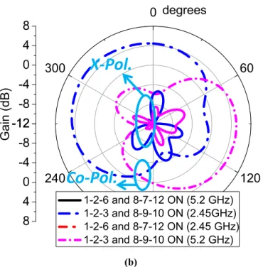
FIGURE 3.13 MEASURED RADIATION PATTERNS OF CASE III:(A)1-2-6 AND 8-7-12 PIN-DIODES ON AT 2.45GHZ AND 5.2GHZ,(B)1-2-3 AND 8-9-10 PIN-DIODES ON AT 2.45GHZ AND 5.2GHZ. ... 39
FIGURE 3.14 SIMULATED RESULTS OF RADIATION PATTERNS IN THE AZIMUTH PLANE:(A)2.45GHZ.(B)5.2GHZ. . ... 41
FIGURE 3.15 MEASURED AND SIMULATED REFLECTION COEFFICIENTS IN CASE III. ... 42
FIGURE 4.1 (A)GEOMETRY OF FSS UNIT-CELL.(B)CONFIGURATION OF FSS UNIT-CELL SIMULATION.(C)E-FIELD DISTRIBUTION AT 2.5GHZ.(D)E-FIELD DISTRIBUTION AT 4.8GHZ.(E)E-FIELD DISTRIBUTION AT 5.2GHZ.(F)
E-FIELD DISTRIBUTION AT 5.8GHZ. ... 45
FIGURE 4.2 SIMULATED TRANSMISSION COEFFICIENTS OF FSS UNIT-CELL IN DIFFERENT PIN-DIODE STATES. ... 46
FIGURE 4.3 PROPOSED BEAM-SWITCHING WITH HIGH GAIN ANTENNA STRUCTURE:(A)TOP VIEW,(B)SIDE VIEW. . 47
FIGURE 4.4 STRUCTURE OF THE MONOPOLE ANTENNA. ... 48
FIGURE 4.5 SIMULATION RESULTS OF THE MONOPOLE ANTENNA:(A)REFLECTION COEFFICIENT.(B)NORMALIZED RADIATION PATTERN AT 5.2GHZ. ... 48
FIGURE 4.6 SIMULATION RESULTS OF THE MONOPOLE ANTENNA:(A)REFLECTION COEFFICIENT.(B)NORMALIZED RADIATION PATTERN AT 5.2GHZ. ... 49
FIGURE 4.7 E-FIELD DISTRIBUTION OF THE ANTENNA AT 5.2GHZ:(A)SINGLE-BEAM MODE.(B)TWO-BEAM MODE. (C)THREE-BEAM MODE. ... 50
FIGURE 4.8 THE EFFECT OF D1 ON THE PROPOSED ANTENNA PERFORMANCES:(A)REFLECTION COEFFICIENTS.(B)
GAIN. ... 51
FIGURE 4.9 THE EFFECT OF D2 ON THE PROPOSED ANTENNA PERFORMANCES:(A)REFLECTION COEFFICIENTS.(B)
GAIN. ... 52
FIGURE 4.10 THE EFFECT OF B ON THE RADIATION PATTERNS OF PROPOSED ANTENNA. ... 53
FIGURE 4.11 THE EFFECT OF H ON THE RADIATION PATTERNS OF PROPOSED ANTENNA. ... 53
FIGURE 4.12 SIMULATED RADIATION PATTERNS OF ANTENNA WITH AND WITHOUT METALLIC SHEETS IN THE AZIMUTH PLANE AT 5.2GHZ. ... 54
FIGURE 4.13 PHOTOGRAPH OF THE FABRICATED ANTENNA IN ANECHOIC CHAMBER. ... 55
FIGURE 4.14 MEASURED REFLECTION COEFFICIENT RESULTS OF PROPOSED ANTENNA IN DIFFERENT MODES. ... 56
FIGURE 4.15 FIG.15MEASURED RADIATION PATTERNS OF A SINGLE-BEAM MODE AT 5.2GHZ:(A),(B) AND (C) IN AZIMUTH PLANE,(D) IN ELEVATION PLANE. ... 58
FIGURE 4.16 SIMULATED AND MEASURED RADIATION PATTERNS OF SINGLE-BEAM MODE WHEN COLUMN 4OFF AT 5.2GHZ IN AZIMUTH PLANE. ... 60
FIGURE 4.17 SIMULATED AND MEASURED RADIATION PATTERNS OF TWO-BEAM MODE AT 5.2GHZ IN AZIMUTH
PLANE:(A)COLUMNS 3 AND 6OFF.(B)COLUMNS 1 AND 3OFF.(3)COLUMNS 1 AND 4OFF. ... 61
FIGURE 4.18 SIMULATED AND MEASURED RADIATION PATTERNS OF THREE-BEAM MODE AT 5.2GHZ IN AZIMUTH PLANE WHEN COLUMN 1,3 AND 5OFF. ... 62
FIGURE 5.1 (A)PROTOTYPE OF PROPOSED NEGATIVE REFRACTIVE INDEX METAMATERIAL (NRIM) UNIT-CELL, AND (B)S-PARAMETERS OF THE PROPOSED NRIM UNIT-CELL. ... 66
FIGURE 5.2 (A)REFRACTIVE-INDEX OF PROPOSED THE NRIM UNIT-CELL AS A FUNCTION OF FREQUENCY, AND (B) EXTRACTED PERMITTIVITY AND PERMEABILITY OF THE NRIM UNIT-CELL. ... 66
FIGURE 5.3 (A)GEOMETRY OF THE PROPOSED DOUBLE-FEED DRA, AND (B)ITS NORMALIZED RADIATION PATTERN IN THE XOZ-PLANE. ... 67
FIGURE 5.4 3D CONFIGURATION OF DOUBLE-FEED DRA WITH 1×4 PROPOSED NRIM ARRAY LOADING.(A)FRONT VIEW, AND (B)SIDE VIEW.(UNIT: MM). ... 67
FIGURE 5.5 RADIATION PATTERN OF DRA WITH AND WITHOUT NRIM LAYERS LOADING EXCITED BY PORT 1 AT 5.2 GHZ. ... 68
FIGURE 5.6 ELECTRIC fiELD DISTRIBUTION IN THE XOZ-PLANE WHEN PORT 1 EXCITED AT 5.2GHZ. ... 69
FIGURE 5.7 PROPOSED BEAM-TILTING ANTENNA FABRICATED AND ASSEMBLED,(A)SIDE VIEW, AND (B)TOP VIEW. . ... 70
FIGURE 5.8 MEASURED REFLECTION COEFFICIENT OF PROPOSED ANTENNA IN DIFFERENT STATES. ... 71
FIGURE 5.9 MEASURED RADIATION PATTERN WITH DIFFERENT INPUT EXCITED AT 5.2GHZ,(A) WITH AND WITHOUT NRIM LOADING IN XOZ-PLANE, AND (B) WITH AND WITHOUT NRIM LOADING IN YOZ-PLANE. ... 71
FIGURE 5.10 MEASURED AND SIMULATED RADIATION PATTERN OF THE PROPOSED ANTENNA WITH DIFFERENT INPUT PORT EXCITED AT:(A)5.1GHZ,(B)5.2GHZ, AND (C)5.3GHZ. ... 72
FIGURE 5.11 SIMULATED AND MEASURED GAIN OF THE ANTENNA WITHOUT AND WITH NRIM STRUCTURES. ... 73
FIGURE 6.1 GEOMETRY OF PROPOSED ANTENNA.(A)TOP VIEW.(B)BOTTOM VIEW AND (C)SIDE VIEW. ... 75
FIGURE 6.2 PHOTOGRAPH OF FABRICATED ANTENNA. ... 77
FIGURE 6.3 MEASURED AND SIMULATED S11 OF PROPOSED ANTENNA IN STATE 1 UP MODE. ... 77
FIGURE 6.4 MEASURED NORMALIZED RADIATION PATTERNS AT 5.2GHZ IN DIFFERENT STATES.(A)AZIMUTH PLANE.(B)ELEVATION PLANE. ... 78
FIGURE 6.5 SIMULATED 3D RADIATION PATTERNS OF STATE 1 DOWN MODE AND STATE 2 UP MODE AT 5.2GHZ. .. 79
FIGURE 8.1 ANTENNE RECONFIGURABLE A STRUCTURE MECANIQUE UTILISANT LA METASURFACE [26]. ... 87
FIGURE 8.2 UNE ANTENNE DE LENTILLE ORIENTABLE A FAISCEAU COMPACT [27]. ... 87
FIGURE 8.3 UN MODELE PLAN COMPACT-RECONFIGURABLE [29]. ... 87
FIGURE 8.4 ANTENNE PLANAIRE ORIENTABLE PAR FAISCEAU UTILISANT UN DISQUE CIRCULAIRE ET DES STUBS EFFILES CONTROLES PAR QUATRE BROCHES [31]. ... 88
FIGURE 8.5 ANTENNES MICRORUBAN SPIRALES RECONFIGURABLES A MOTIF DE RAYONNEMENT AVEC COMMUTATEURS RFMEMS[36]. ... 89
FIGURE 8.6 UN DIAGRAMME DE RAYONNEMENT RECONFIGURABLE ANTENNE A SPIRALE DE FAISCEAU DE
BALAYAGE [37]. ... 89
FIGURE 8.7 ANTENNE RECONFIGURABLE A DIAGRAMME DE RAYONNEMENT AVEC DIODE VARACTOR [42]. ... 90
FIGURE 8.8 PHOTOGRAPHIE DE L'ANTENNE RECONFIGURABLE EN FREQUENCE ET EN DIAGRAMMES DE RAYONNEMENT A L'AIDE DE COMMUTATEURS PHOTOCONDUCTEURS [47]. ... 92
FIGURE 8.9 GEOMETRIE DE BASE DE L'ANTENNE DE BALAYAGE A BASE DE SUBSTRAT FERROELECTRIQUE [52]... 92
FIGURE 8.10 ANTENNE DE FAISCEAU COMMUTABLE BASEE SUR LA BANDE INTERDITE ELECTROMAGNETIQUE (EBG)[58]. ... 93
FIGURE 8.11 ANTENNE RECONFIGURABLE EN DIAGRAMME DE RAYONNEMENT UTILISANT UNE SURFACE A HAUTE IMPEDANCE (HIS)[63]. ... 94
FIGURE 8.12 UNE ANTENNE RECONFIGURABLE EN DIAGRAMME DE RAYONNEMENT BASEE SUR LA SURFACE SELECTIVE DE FREQUENCE (FSS)[69]... 94
FIGURE 8.13 ANTENNES ORIENTABLES A DIAGRAMME DE RAYONNEMENT BASE SUR L'AFSS[73],(A)STRUCTURE DE L'ANTENNE ET INSTALLATION.(B)SCHEMAS DE RAYONNEMENT DES MODES A FAISCEAU UNIQUE ET DES MODES A DOUBLE FAISCEAU. ... 95
FIGURE 8.14 LES STRUCTURES DE BASE ET LEUR REPONSE EN FREQUENCE. ... 97
FIGURE 8.15 LES ELEMENTS TYPIQUES DES FSSS. ... 98
FIGURE 8.16 SCHEMA DE PRINCIPE DU RADOME. ... 99
FIGURE 8.17 DIAGRAMME SCHEMATIQUE DU FSS EN TANT QUE SOUS-REFLECTEUR DANS LES SYSTEMES D'ANTENNES. ... 99
1
INTRODUCTION
1.1 Background and motivation
Wireless communication systems have become one of the fastest growing areas. The new generation of mobile communications, wireless LAN, satellite positioning system, a variety of military and civil radars have become more and more important in our daily live. As one of the most important elements in wireless communication systems, the operating characteristics of an antenna directly affect system performances [1-2]. The rapid development of modern wireless communication systems has put forward higher requirements such as multifunction, high-capacity and ultra-wideband, which directly leads to an increasing number of subsystems on the same platform while the number of antennas is also correspondingly increased. As a result, there are several problems arise such as large volume, high costs and electromagnetic compatibility. As it has become more and more difficult to meet these requirements using traditional antennas whose performances are fixed in many applications, a variety of new antennas are being gradually developed. A reconfigurable antenna is one of these antennas, which not only meets the development requirements of wireless communications, but also have simple structures and small sizes [3-4].
A reconfigurable antenna is referred to any radiation structure which is controlled by means of electrical, light, mechanical approaches to change one or some of its fundamental operating characteristics. The key principle in designing reconfigurable antennas is based on the theory of conventional antennas. Their desired radiation characteristics are shifted by adjusting the radiator structure, controlling the current distribution, or changing the electrical parameters of the antenna [5]. Reconfigurable antennas are able to independently tune their operating frequency, bandwidth, polarization, and radiation-pattern to accommodate changing operation requirements [6].
According to the reconstruction performance, reconfigurable antennas can be classified into frequency reconfigurable antennas, polarized reconfigurable antennas, radiation pattern reconfigurable antennas, and multi-performance reconfigurable antennas [7]. The frequency reconfigurable antennas have ability to tune the working frequency band, which can filter out the interfering signals, or tune the antenna to account for the new environments [8-11]. For the
polarized reconfigurable antennas, polarization of the antenna can be reconfigured to separate desired signals and filter the unwanted signals [12-14]. In addition, the radiation pattern reconfiguration antennas can change the direction of main beam to send EM signals to the desired direction effectively [15-16]. These antennas can significantly decrease interfering signals and improve the system capacity. Multi-performance reconfigurable antennas are two or three kinds of antennas with variable performance, such as frequency and radiation pattern reconfigurable antennas, frequency and polarization reconfigurable antennas, radiation pattern and polarization reconfigurable antennas [17-19]. In this thesis, our main research is focused on designing new radiation pattern reconfigurable antennas.
Radiation-pattern reconfigurable antennas can bring several improvements and enhancements for modern wireless communication systems. Firstly, using the radiation pattern reconfigurable antenna, aligning the main radiation direction of the antenna with the useful signal direction can increase signal-to-noise ratio, improve system performance and reduce power consumption [7]. Secondly, as multi-input multi-output (MIMO) technology has able to increase capacity of system, it mostly will be used in 5G communication systems. MIMO systems need to integrate multiple antennas in a limited space, hence, it requires a weak coupling between antenna elements. Radiation-pattern reconfigurable antennas can effectively reduce the mutual coupling between elements in MIMO systems [20-21]. Thirdly, to fulfill the requirements of miniaturization and multifunction in modern communication systems, more and more electronic devices are integrated into a single platform. Although this method can significantly improve the communication quality, it can also lead to serious problems of interference. Radiation pattern reconfigurable antennas can reduce the interference coming from undesired radiation to enhance the communication performance [22].
In summary, radiation pattern reconfigurable antennas can reduce the size, cost and design complexity of a wireless communication system, which greatly improves the overall performance of a wireless communication system. The outstanding advantages of these antennas for wireless modern communication systems have motivated us to establish a comprehensive research in this field. Therefore, this project aims to design, analyze, and prototype novel dual-band radiation-pattern reconfigurable antennas for wireless modern communication systems.
1.2 Research status of radiation pattern reconfigurable antenna
In recent years, more and more researchers have focued their interests on radiation- pattern reconfigurable antennas. One of the most traditional methods to design radiation pattern reconfigurable antennas is to use phased arrays [23-24], in which to control the radiation pattern of antenna is realized by changing the phase of the phase shifter. However, the complex feeding network of phased antenna array leads to the problems of high costs and complex design processes. Compared to phased antenna arrays, radiation pattern reconfigurable antennas have a simple structure and a relatively easy design process has attracted researchers’ significant interest. According to the different implementation methods, radiation pattern reconfigurable antennas can be classified into mechanical controlling method, electrical controlling method, optical controlling method, changing the material property method or using metamaterial method.
1.2.1 Mechanical controlling method
Mechanical steering is achieved by repositioning and moving the antenna to reach the intended characteristics. However, the applications of the mechanical approach are limited by its low speed and complex system installation [25-27]. In [26], Hai Liang Zhu et al. have proposed a radiation pattern reconfigurable antenna that is composed of a planar semi-circular metasurface placed directly at the top of a planar circular patch antenna, shown in Fig. 1.1. By rotating the metasurface around the centre of the patch antenna, the antenna beam can be continuously steered. The main-beam direction of the antenna steered to an angle of 32° from the boresight direction. In [27], Jorge R. Costa et al. have designed a steerable beam antenna composed of a dielectric lens that pivots in front of a single stationary moderate gain feed, shown in Fig.1.2. This antenna can steer the main beam in the elevation and full azimuth plane mechanically.
Figure 1.2 A compact beam-steerable lens antenna [27].
1.2.2 Electrical controlling method
Electrical controlling methods to design reconfigurable antennas ues RF switching components and variable reactance devices. RF switches can be used to connect / disconnect a part of the antenna structure or change the distribution of current to achieve different performances of antennas. Microwave switching components mainly include pin-diodes and radio frequency micro-electromechanical systems (RF-MEMS) switches. For variable reactance devices, they are mainly varactor diodes. In the literature, many radiation pattern reconfigurable antennas are controlled by pin-diodes [28-34]. Pin-diodes have small insertion loss, fast switching speedand low DC bias voltage. They can control large current microwave signal conduction and cut off. In [29], Tamer Aboufoul et al. have proposed a compact planar pattern reconfigurable by incorporation of four pin-diode switches and two parasitic elements, as shown in Fig.1.3. The radiation patterns of this antenna could be changed from a nearly omnidirectional into two opposite end-fire patterns. In [31], M. S. Alam et al. have designed a planar beam-steerable antenna, which includes a central circular disc surrounded by four PIN-controlled tapered microstrip stubs, as shown in Fig.1.4. Using Pin-diodes, the stubs change their status from grounded to open-ended mode to provide pattern reconfigurability in four directions.
Figure 1.3 A compact planar pattern-reconfigurable [29].
Figure 1.4 A Beam-Steerable Planar Antenna Using Circular Disc and Four PIN-Controlled Tapered Stubs [31].
RF-MEMS switches are a new type of RF devices. As early as 1998, E. R. Brown proposed the use of RF-MEMS switches to design a reconfigurable antenna [35]. More and more studies have been reported in [36-41]. One of the major advantages of RF-MEMS switches is their good isolation and low-loss property. They can be used at microwave frequencies with good linearity. However, a disadvantage of MEMS switches is their slower response compared to pin-diodes, and the bias voltage is higher than pin-diodes [20]. In [36], Greg H. Huff et al. have designed a radiation pattern reconfigurable microstrip antenna with microelectromechanical system (MEMS) switches. Two MEMS switches are used to reconfigure the radiation patterns of a resonant square spiral microstrip antenna between endfire and broadside modes over a common impedance bandwidth. The designed and fabricated antennas are shown in Fig.1.5. The antenna shown in Fig. 1.6 is a reconfigurable rectangular spiral antenna with a set of RF-MEMS switches, which is fed through a coaxial cable at its center point. The structure consists of five sections that
are connected with four RF-MEMS switches. Based on the status of the integrated RF-MEMS, the antenna can change its radiation beam direction [37].
Figure 1.5 Radiation pattern reconfigurable square spiral microstrip antennas with RF MEMS Switches [36].
Figure 1.7 A radiation pattern reconfigurable antenna with varactor diode [42].
Varactor diode is a commonly used in microwave solid-state device, the capacitance between the two poles changes with the DC bias voltage change. Varactor diode can be used to continuously adjust the operating frequency of antennas to achieve continuous adjustable antenna radiation performances [42-45]. Another reconfigurable antenna, shown in Fig.1.7, has been presented in [42], it is based on a two-element dipole array model. The two dipoles of the array are folded to form a square and the phases of the magnetic dipoles are adjusted by the loaded varactor diodes. The radiation patterns of this antenna are reconfigured in two orthogonal planes.
1.2.3 Optical controlling method
Thirdly, optical controlled reconfigurable antennas are based primarily on photoconducting switches. The laser light is used to tune a photoconducting switch. Compared to the traditional microwave switching devices, photoconducting switches do not require additional DC bias wire, thereby reducing the radiation effects on the antenna. In additon, they do not need to consider the isolation between the positive and negative DC bias voltage, which reduces the complexity of antenna structures. However, the most challenges of this reconfigurable technology are integration and power consumption because laser generation needs laser diodes and fiber optics. Photoconducting switches have commonly been used to design frequency reconfigurable antennas [46-50]. C. J. Panagamuwa et al. have designed a frequency and beam reconfigurable antenna using phototconducting switches, which is shown in Fig.1.8. From this, we find that two silicon photo switches are placed on small gaps in both dipole arms equidistant from the centre feed. Light from two infrared laser diodes is channelled through fiber optic cables and applied on the switches. With the gaps in the dipole bridged, the antenna resonates at lower frequencies.
Therefore, the lengths of the two arms of antenna were effectively changed by using a laser to control the photoconducting switches, the frequency and beam reconfigurable antenna was achieved [47].
1.2.4 Changing the material properties method
Changing the material properties is another interesting method to design radiation-pattern and frequency reconfigurable antenna [51-53]. Liquid crystals (LC), ferroelectric and ferromagnetic materials are some kind of these materials, which have been used as means of reconfiguration. By applying DC voltage or magnetic field on these materials, their electrical properties of them are modified, leading to alter the EM responses of the structures. In [51] and [52], a fixed-frequency beam scanning antenna has been designed by using a ferroelectric substrate, as shown in Fig.1.9. By changing the DC bias voltage on the substrate, the permittivity of the ferroelectric material is changed. Hence, electrically phase constant of the propagation wave is changed and the direction of the main beam could be changed.However, the higher cross polarization level in the ferromagnetic material limits its applications as radiators in the antenna engineering.
Figure 1.8 Photograph of frequency and beam reconfigurable antenna using photoconducting switches [47].
1.2.5 Using metamaterial method
In recent years, metamaterials has increasingly attracted researchers’ attention to develop new antennas and RF devices [54-56]. Depending on the way that they treat with the incident electromagnetic waves, metamaterials can be realized as Electromagnetic Bandgap structures (EBG), Artificial Magnetic Conductor (AMC), High Impedance Surface (HIS) and Frequency Selective Surfaces (FSS). They are constructed of an array of periodic elements arranged in one, two or three dimensional pattern. There have been many structures such metamaterials that are used to design radiation pattern reconfigurable antennas because of their specific performances on electromagnetic waves [57-75].
In [58], M.A. Habit et al. have proposed a switching beam antenna based on electromagnetic bandgap (EBG) periodic structures. This antenna operats at 1.8GHz with a gain of 10dBi, and it switchs in six different beams with 60° of beam-width and covered 360° in the azimuth plane, which is shown in Fig.1.10. Fig.1.11 shows a pattern reconfigurable antenna with four open circuit switches over a high-impedance surface (HIS) proposed in [63]. By switching different switch combinations, beam steering is achieved. From references [64-75], the designs of radiation pattern reconfigurable antennas were based on frequency selective surfaces (FSS). In [69], Arezou Edalati et al. have proposed a reconfigurable antenna using an active cylindrical FSS, as shown in Fig.1.12. The FSS structure consists of metallic discontinuous strips with Pin-diodes in their discontinuities. An omnidirectional electromagnetically coupled coaxial dipole (ECCD) array is surrounded by cylindrically FSS. By controlling the state of diodes in FSS, a directive radiation pattern can be swept in the entire azimuth plane. In [73], Liang Zhang et al. have designed a beam steerable antenna system using active frequency selective surfaces (AFSS), as shown in Fig.1.13. The varactors are mounted on this AFSS to achieve continuous tuning. The reflection band changes with the reverse voltage added on the varactor diodes continuously. The beam of this antenna could sweep in the whole azimuth plane for both the single-beam modes and the dual-beam modes.
Figure 1.10 A beam switching antenna based on electromagnetic bandgap (EBG) [58].
Figure 1.11 A pattern reconfigurable antenna using a high-impedance surface (HIS) [63].
(a)
(b)
Figure 1.13 A radiation pattern steerable antennas based on AFSS [73], (a) Antenna structure and installation. (b) Radiation patterns of single-beam modes and dual-beam modes.
Table 1.1 Comparison of different reconfigurable approaches.
Design Methods Advantages Disadvantages
Mechanical Continuously steering,low insertion loss Low speed and complex system installation
Pin-diode Fast speed, low cost More insertion losses, isolation reducing with the frequency increasing, need to design the DC bias circuit
RF-MEMS High isolation, low insertion losses, low power consumption
Slow speed, high bias voltage, high cost
Varactor
Continuously adjustable, low insertion
losses, low power consumption Requires a stable bias voltage
Photoconducting switches
Do not need additional DC bias wires High cost and difficult integration
Changing the material
properties More designing freedom High bias voltage, more losses, high cross polarization
Using metamaterial Fast speed, small size, more designing freedom, low power consumption
Need to design the DC bias circuit
In summary, the mentioned reconfiguration approaches above are compared in Tab. 1-1. Based on the data listed in this table, it can be concluded that implementing a reconfigurable structure using metamaterial technology makes the antenna performances better in terms of loss, speed, power consumption and freedom degree for design.
1.3 Research objectives
The main objective of the research is to develop a compact, low-profile, low cost antenna which has the functionality to switch the direction of the main beam in the azimuth and elevation planes without severely affecting its performance. In the design process, the number of active elements needs is kept as minimum as possible to decrease the antenna cost and also to enhance its radiation performance in terms of gain.
1.4 Organization of the thesis
This thesis is divided into 8 chapters including the abstract and the reference. The contents of the dissertation chapters are listed below.
Chapter 1 firstly introduces the background and motivation of research on radiation pattern reconfigurable antennas. Research status of radiation pattern reconfigurable antenna are also presented. Moreover, the most commonly used reconfiguration approaches are also described and compared to each other in this chapter.
Following the research survey presented in the first chapter, comprehensive studies on frequency selective surfaces are presented in Chapter 2.
Chapter 3 describes a compact dual-band beam-sweeping antenna which consists of two independent cylindrical active frequency selective surfaces (AFSS) and a dual-band omnidirectional monopole antenna. The unit-cells of the two proposed AFSS screens are designed. The transmission and reflection characteristics of the unit-cell of the two AFSS are also investigated, respectively, at their own operating frequency.Then the operation mechanism of the dual-band beam switching antenna and parametric studies are introduced and discussed in this chapter. At last, the simulation and measurement results of the proposed design are depicted, indicating that it can effectively realize beam-sweeping at 2.45 GHz and 5.2 GHz covering all azimuth angles simultaneously. The size of the proposed antenna system is reduced greatly by using this method.
Chapter 4 presents a beam-switching antenna with high gain and flexible control of beam numbers based on FSS. This presented high gain antenna is composed of an omnidirectional monopole antenna as radiating source surrounded by a hexagon FSS screen and six metallic sheets. The design of the FSS unit-cell used in this desgin is presented in this part. The transmission and reflection characteristics of FSS unit-cell are also investigated at 5.2 GHz. Then the operation mechanism of this high gain beam swiching antenna and parametric studies are described and discussed. At last, the simulation and measurement results of the proposed design are depicted. By switching the states of the pin-diodes in the hexagon FSS screen, the proposed antenna not only sweeps six directions with high gain in the azimuth plane, but also flexibly operates at multiple beam modes, including two-beam mode and three-beam mode with low power at 5.2 GHz. Moreover, the result shows that the maximum gain of this proposed antenna has been enhanced by 7 dB when six metallic sheets are applied to the design.
Chapter 5 proposes a beam-tilting antenna with negative refractive index metamaterial (NRIM) loading. The proposed antenna is composed of a double-feed dielectric resonator antenna (DRA)
and 1×4 NRIM array which are fixed over and in the middle of the DRA. The NRIM unit cell and double feed dieletric resonator antenna are designed. Then, the working mechanism of the beam tilting antenna is discussed and the simulation and experimental results are shown in this chapter. From these results, this designed antenna can steer the main beam by ±38o in the
xoz-plane over 5 to 5.5 GHz band. In the operating frequency band, the reflection coefficient is better than -10 dB. Moreover, the measured results are in a good agreement with simulated ones. In chapter 6, a three layers pattern reconfigurable quasi-yagi antenna is proposed. This design achieved multi beam directions in both elevation and azimuth planes at 5.2 GHz. There are four elements of quasi-Yagi antenna and eight pin-diodes as switches inserted in the middle layer. The parasitic elements are included in the top and bottom layers, into which pin-diodes are inserted. By controlling the pin-diodes in the middle layer, the antenna can realize beam switching in the azimuth plane in four directions. Moreover, beam tilting in the elevation plane is achieved by activating the pin-diodes in the top and bottom layers to reconfigure the lengths of the parasitic elements. The performance is very advantageous for modern wireless communication.
In chapter 7, the accomplishments of this thesis is summarized, and the future work is proposed in the research orientation.
1.5 List of publications
Journals
[1]. J. Li, Q. Zeng, R. Liu and T. A. Denidni, “A Compact Dual-Band Beam-Sweeping Antenna Based on Active Frequency Selective Surfaces,” IEEE Trans. Antennas Propag., vol. 65, no. 4, pp. 1542-1549, April 2017.
[2]. J. Li, Q. Zeng, R. Liu and T. A. Denidni, "Beam-Tilting Antenna With Negative Refractive Index Metamaterial Loading," IEEE Antennas Wireless Propag. Lett., vol. 16, pp. 2030-2033, 2017.
[3]. J. Li, Q. Zeng, R. Liu and T. A. Denidni, “A Gain Enhancement and Flexible Control of Beam Numbers Antenna Based on Frequency Selective Surfaces,” IEEE Access, vol. 6, pp. 6082-6091, 2018.
[4]. J. Li, Q. Zeng and T. A. Denidni, “Pattern-reconfigurable antenna for elevation and azimuth planes.” Microwave and optical technology letters. Submitted
Conference
[5]. J. Li, Q. Zeng and T. A. Denidni, "A beam switching antenna with gain enhancement," 2017
IEEE International Symposium on Antennas and Propagation & USNC/URSI National Radio Science Meeting, San Diego, CA, 2017, pp. 1981-1982.
[6]. J. Li, T. A. Denidni and Q. Zeng, "A dual-band reconfigurable radiation pattern antenna based on active frequency selective surfaces," 2016 IEEE International Symposium on Antennas
and Propagation (APSURSI), Fajardo, 2016, pp. 1245-1246.
[7]. Jinxin Li, T. A. Denidni, Ruizhi Liu and Qingsheng Zeng, "Beam-tilting antenna with metamaterial loading," 2016 Progress in Electromagnetic Research Symposium (PIERS), Shanghai, 2016, pp. 4830-4830.
[8]. J. Li, T. A. Denidni and Q. Zeng, "A compact gain-enhancement patch antenna based on near-zero-index metamaterial superstrate," 2016 17th International Symposium on Antenna
[9]. J. Li, T. A. Denidni and Q. Zeng, "High gain reconfigurable millimeter-wave dielectric resonator antenna," 2015 IEEE International Symposium on Antennas and Propagation &
USNC/URSI National Radio Science Meeting, Vancouver, BC, 2015, pp. 444-445.
[10]. J. Li, T. A. Denidni and Q. Zeng, "Beam switching antenna based on active frequency selective surfaces," 2015 IEEE MTT-S International Conference on Numerical Electromagnetic
and Multiphysics Modeling and Optimization (NEMO), Ottawa, ON, 2015, pp. 1-3.
[11]. Jinxin Li, T. A. Denidni, Qingsheng Zeng and Wenmei Zhang, "Active frequency selective surfaces for beam switching applications," 2015 IEEE 6th International Symposium on
Microwave Antenna Propagation and EMC Technologies (MAPE), Shanghai, 2015, pp. 816-818.
[12]. J. Li, Q. Zeng and T. A. Denidni, "Pattern Reconfigurable Antenna Loaded with Frequency Selective Surface and Artificial Dielectric Medium," 2018 IEEE International Symposium on
2
FREQUENCY SELECTIVE SURFACES
Frequency selective surfaces (FSSs) are a two-dimensional or three-dimensional periodic structure, which is usually composed of an infinite array of metal patches or an array of apertures in a metal sheet based on a dielectric substrate. FSSs have originally been developed as a kind of spatial filter because of their responses to the electromagnetic (EM) waves. FSSs can transmit nearly all EM waves over a specific bandwidth while reflecting nearly all energy through another frequency bandwidth. According to the filter characteristics, FSSs can be divided into low-pass, high-pass, band-stop and bandpass four types. The basic structures and their frequency response are shown in Fig. 2.1. The orange color in the figure shows the metal material. From Fig. 2.1, the metal grid provides high-pass filter characteristics on the electromagnetic field and the patches provide low-pass filter characteristics, while the metal and the apertures have band-stop and band-pass filtering characteristics, respectively [76-78].
Figure 2.1 The basic structures and their frequency response.
There are many different shapes of FSS elements. Generally, these elements may be broadly classified into four categories: center connected, loop elements, solid interior elements and combination elements,shown in Fig. 2.2 [7]. The first group is center connected elements, some typical elements of the first group are a straight element, three-legged element, anchor element and Jerusalem cross. The second group is loop elements, the typical elements of which include
three- and four-legged loaded elements, square and hexagonal loops. The third group is solid interior elements which usually includes such as square patch, hexagon patch, circle patch and triangle patch. The fourth group is combination elements which are constructed by a combination of the other three group members. By tailoring or combining other elements, the different types of combination elements are designed to meet the demands of desired application.
Figure 2.2 The typical FSSs elements[7].
2.1 Applications of frequency selective surfaces
The first FSS prototype as a partially reflector surface has been reported in 1919 by Marconi and Franklin. However, until to the mid-1960s, FSSs were deeply investigated theoretical, and experimental, and were widely used in many fields [76].
One example of FSS applications is the shielding on the door of a microwave oven that allows us to see the food inside without being radiated by the electromagnetic waves of the microwave oven because the shielding is made of FSSs. The FSSs reflect microwave energy and allows visible light to pass through. In addition, there are many places using FSSs in civil applications , such as anti-collision systems for autonomous vehicles, electromagnetic shielding devices in public places such as hospitals and airports, robotic navigation systems, band gap structures of photonic crystals, etc.
Another important application is that the FSSs can be used in the military domain as radomes, which can decrease the radar cross section (RCS) of communication antennas and hide them from the enemy. Radomes work by allowing only the operational frequencies to pass through and rejecting the other frequencies that lie outside this band [76], whose schematic diagram is shown in Fig.2.3.
Figure 2.3 Schematic diagram of radome.
Figure 2.4 A schematic diagram of FSS as sub-reflector in antenna systems.
There is another very typical application in the microwave antenna field. In order to improve the utilization efficiency of antennas, the FSSs have also been used as a sub-reflector in antenna systems to achieve multi-frequency operation [76]. As shown Fig.2.4, the FSSs are designed as a sub-recflectors placed between two different frequency feeds in a reflector antenna system. The FSS is transparent for feed 1 in the first operating band, while it operates as a sub-reflector in the second working frequency band for feed 2. Therefore, by using only one main reflector at two different operating frequencies, not only the size and cost of antenna systems are reduced but also the efficiencies of antennas has been improved [76].
2.2 Design parameters for frequency selective surfaces
The main design parameters of the FSS are the center frequency, transmittance and 3 dB bandwidth. A good FSS structure should have stable transmission characteristics with different angles of incidence and polarization. There are many factors affecting the FSS transmission
characteristics, including the unit cell structure, arrangement way and period, the thickness of the dielectric, dielectric constant, dielectric loss, number of layers.
Firstly, the FSS unit cell is the main factor affecting the center frequency of FSS, which directly determines the performance of the FSS. For some simple structures of unit cell, the center frequencies can be estimated. For example, for a dipole structure, a half wave resonance occurs when the length of unit cell is an integer multiple of the half wavelength of the incident wave. In addition, the better the symmetry of any unit cell, the better the polarization stability and the angular stability [76].
Secondly, the periodic structure and the arrangement way of FSS are also important parameters could affect the final transmission/reflection response of the FSS. Therefore, depending on the application features, both structures and arrangement way of FSS must be carefully chosen to meet all demands. The distance of elements and the geometrical position of adjacent elements significantly affect the center frequency, bandwidth, angular sensitivity, and cross polarization level.
Thirdly, the FSS screens have to be supported by dielectric substrate in practice because of mechanical reasons. In general, the resonant frequency of the dielectric drifts to the high frequency when the incident angle increases, while the FSS resonance frequency shifts to the low frequencies when the incident angle increases. Therefore, bonding the FSS in one side to dielectric or embedding it with dielectric on both sides significantly changes its transmission responses and can improve the structural stability of the angle [76]. In addition, dielectric loaded FSS structures have a wider available bandwidth. The thickness of dielectric also has influence on the FSS response with changing the incident angle and polarization. To achieve an angular stable resonant slot, the thickness of dielectric on both sides of the FSS must be a multiple of a quarter wavelength. When the FSS is loaded with one side dielectric, its thickness has to be a multiple of a half-wavelength to eliminate the mismatch loss[76].
2.3 Research states of active frequency selective surfaces
Once the passive FSS is manufactured, the electromagnetic characteristics such as the resonance frequency and the working bandwidth cannot be changed. The FSS radome in the working
frequency band cannot flexibly adapt to change according to the external electromagnetic environment, while the active FSS can solve this problem. Therefore, active FSS has become a popular research topic. Active FSS is also known as tunable FSS, controllable FSS and reconfigurable FSS. Based on a variety of different principles, active frequency selective surfaces are realized commonly using electronically controlled elements and materials in the microwave field. Controllable dielectric materials in the microwave and millimeter-wave bands have a wide range of applications, such as liquid crystal and ferrite materials are excellent controllable materials [79]. At present, there are many active frequency selective surface studies based on such controllable dielectric materials. Another type of active frequency selective surface is based on electronic control components to achieve the purpose of electronic control, including MEMS switches, PIN diode switches, as well as varactor diodes. MEMS switches have good high frequency characteristics, such as advantages of high integration, small size, low loss and low harmonics. Frequency selective surface current paths can be controlled using RF MEMS switches [80, 81], as an example shown in Fig.2.5. However, MEMS switches have not been widely marketed for manufacture as the cost is high and therefore designing active frequency selective surfaces based on MEMS switches is limited.
Pin-diodes have two different states which can be turned on and off in the high frequency band, so pin-diodes are often used as microwave band switches. Varactor diodes are very similar to pin-diodes, which capacitances are controlled by controlling the reverse bias voltage on them. Due to the maturity of pin-diodes and varactor diodes, the tunable frequency selective surface can be realized by the switching characteristics of pin-diodes and varactor diodes [82-87], as shown in Fig.2.6.
(a) (b)
Figure 2.6 Tunabal FSS structure using (a) pin-diodes and (b) varactor diodes[82].
2.4 Introduction of theoretical analysis methods of FSS
The continuous improvement of FSS theoretical analysis methods has promoted the development of FSS. Theoretical analysis method is the basis of FSS characteristic analysis and engineering application. It mainly includes two major categories: equivalent circuit method and full wave analysis method.
The equivalent circuit method is based on the assumption of quasi-static field. FSS structural elements are equivalent to inductive and capacitive elements based on the theory of transmission lines. By using the inductance calculation formula of infinite metal strip and the capacitance calculation formula between adjacent strips, the equivalent circuit parameters can be achieved. Hence, the FSS transmission / reflection characteristics are achieved. The equivalent circuit method can directly reflect the filtering mechanism of the FSS structure and quickly obtain the resonance characteristics of the FSS. Especially in the beginning of design, the design process can be speed up by adopting this method. The limitations of this method lie in that the equivalent circuit parameters of the irregular and complex FSS structures are not easily obtained. The equivalent circuit parameters obtained by quasi-static approximation method have limited accuracy, hence, exact solutions of FSS scattering parameters cannot be obtained [88-92]. The full wave analysis method applies a strict vector method, which can obtain the amplitude of the FSS transmission coefficient, as well as phase and polarization characteristics of FSS. Full wave analysis method includes finite difference in frequency domain, spectral domain approach, volume integral equation method, periodic moment method and finite element method [93-98].
3
DESIGN OF A DUAL-BAND BEAM SWEEPING ANTENNA USING
ACTIVE SURFACE SELECTIVE SURFACES
3.1 Introduction
Nowdays, to fulfill the requirements of miniaturization and multifunction in the modern communication systems, more and more electronic devices are integrated into a single platform. Although this method can significantly improve the communication quality, it can also lead to serious problems of interference. As a means of reducing the interference coming from undesired radiation and to enhance the communication performance, radiation pattern reconfigurable antennas have intensively been investigated and received much attention. These antennas can significantly decrease interfering signals and improve the system capacity, while occupying the same or even a smaller physical volume in comparison with traditional smart antennas [22]. In the past few decades, various methods for designing radiation pattern reconfigurable antennas were reported. A conventional method for achieving radiation pattern reconfigurability is the introduction of phased antenna arrays [23,24,99]. However, the complex feed networks of phased arrays make the total antenna structure bulky, complicated and expensive to be applied in practice. On the other hand, many considerable advantages of electrical steerable antennas, such as a low-profile and simple structure, easy and inexpensive fabrication, have been reported. The concept of electronically steerable antenna has early been introduced by Harrington [100], which provides an easier way to obtain the variation of radiation pattern. There are three basic types of reconfigurable mechanisms utilized for electronically steerable antennas: pin-diodes [101-103], varactors [73] and RF micro-electromechanical system (MEMS) switches [37]. Recently, active frequency selective surfaces (AFSS) have been used to modify electromagnetic wave propagation, which has drawn significant interest. By employing active components like pin-diodes and varactors, AFSS could achieve a high level of control over electromagnetic wave propagation [67-75,104].
The traditional reconfigurable antennas could change the radiation pattern dynamically only in a single operating band with a large volume due to the configuration of unit-cells of FSS. In this chapter, a compact dual-band beam-sweeping antenna is presented. The radiating source is a
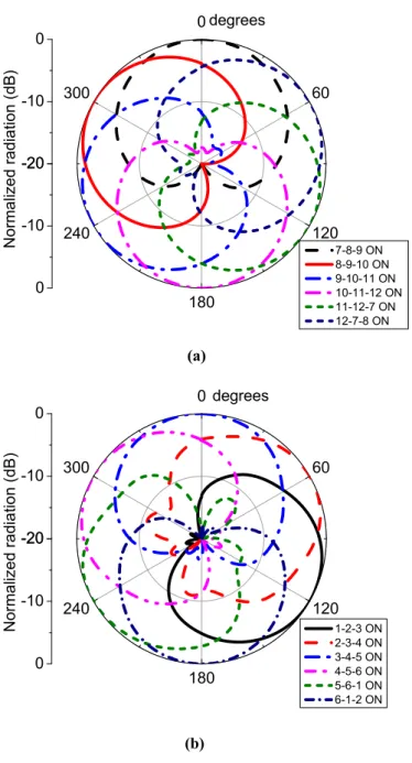
dual-band omnidirectional monopole antenna, which is surrounded by two cylindrical AFSS screens with different operating frequencies. The proposed design can realize dual-band beam-sweeping characteristics in 6 discrete states of radiation patterns, respectively, at 2.45 GHz and 5.2 GHz by switching pin-diodes on two AFSS screens. Both AFSS screens are made up of 6 unit-cells each, dividing the azimuth plane into 6 equal parts of 60o. By switching pin-diodes
between the forward biased and reversed biased states in both AFSS screens, six types of radiation pattern could be created and cover the entire azimuth plane at both frequencies. Therefore, the omnidirectional radiation pattern of the dual-band monopole antenna can be converted into a directional one. From the simulated and measured results, the matching conditions of the proposed dual-band beam-sweeping can be guaranteed at 2.45 GHz and 5.2 GHz.
3.2 Active frquency selective surfaces unit cell design
(a) (b)
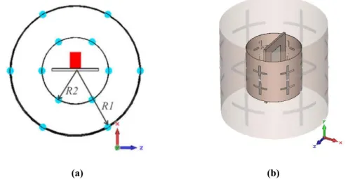
Figure 3.1 Geometry of AFSS unit-cells: (a) 2.45 GHz AFSS unit-cell, (b) 5.2 GHz AFSS unit-cell.
Table 3.1 Final dimensions of two AFSS unit cells(unit:mm).
2.45 GHz AFSS Unit cell Parameters W1 L1 W2 L2 g1 t1 _ Value 36.6 65 24.7 24.7 1.3 2.3 _ 5.2 GHz AFSS Unit cell Parameters W3 L3 W4 L4 g2 t2 t3 Value 18.8 30 10 10 1.4 1 1.5
The geometry of the proposed AFSS unit-cells operated at 2.45 GHz and 5.2 GHz are shown in Fig.3.1. Each AFSS unit-cell contains two metallic crosses connected by a pin-diode in serial. The cross structure is chosen here due to its simplicity and symmetrical structures. Moreover, a cross structure can also provide an acceptable angular and polarizations stability. Both proposed AFSS unit-cell structures are printed on the RT/duroid® 5880 substrate with a relative permittivity of εr = 2.2 and a thickness of h = 0.127 mm. The dimensions of the 2.45 GHz and 5.2 GHz AFSS unit-cells are shown in Table 3.1. The AFSS unit-cells are simulated using CST Microwave Studio with the unit-cell boundary conditions applied along the x and y axis and two ports located along the z direction, in which the pin-diode is modeled as RLC serial lumped elements. In the forward biased case (state ON), the diode mainly represents a small resistance of
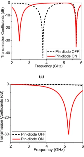
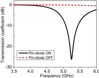
Rs = 1.8 Ω. When it is reversely biased (state OFF), the diode is equivalent to a capacitance Cp = 0.09 pF and an inductance Lp = 0.5 nH in series [71]. By switching the ON and OFF states of the pin-diodes, two metallic crosses can be either connected or isolated electrically, which leads to the variation of transmitting characteristics of the unit-cells at their own operating frequencies. Fig. 3.2 (a) shows the simulated transmission coefficients of the 2.45 GHz AFSS unit-cell in both ON and OFF states, clearly indicating that the proposed 2.45 GHz AFSS unit-cell offers a band-stop and band-pass at 2.45 GHz when the pin-diode is ON and OFF, respectively. It is worth mentioning that the 2.45 GHz AFSS unit-cell always transmit the electromagnetic waves at 5.2 GHz no matter which state of the pin-diode is in. The simulated transmission coefficients of the 5.2 GHz AFSS unit-cell with different pin-diode states are illustrated in Fig. 3.2 (b), showing that electromagnetic waves are reflected and transmitted by the AFSS unit-cell at 5.2 GHz when the diode is ON and OFF, respectively.
As can be seen from it, when the diode is ON, electromagnetic waves can be reflected by the AFSS unit-cell. When the diode is OFF, the AFSS unit-cell can transmit electromagnetic waves at 5.2 GHz. Similar to the 2.45 GHz AFSS unit-cell, the 5.2 GHz AFSS unit-cell is always transparent to electromagnetic waves at 2.45 GHz regardless of which state of the pin-diode is in. With the “transparent” characteristics of unit-cells, each AFSS could work independently when placed together in one antenna system.
(a)
(b)
Figure 3.2 Simulated transmission coefficients of the AFSS unit-cells: (a) 2.45 GHz AFSS unit-cell, (b) 5.2 GHz AFSS unit-cell.
3.3 Design and operation mechanism
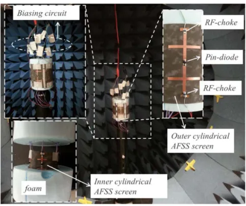
The proposed dual-band beam-sweeping antenna schematic is shown in Fig. 3.3. For clarity, the outer cylindrical AFSS screen is made transparent in perspective view shown in Fig. 3.3 (b). A dual-band monopole antenna in the center is designed as a radiating source and surrounded by two proposed cylindrical AFSS screens that have a common center. Each cylindrical AFSS screen consists of six AFSS unit-cells, subtending an angle of 60 degree at the center of the cylinder. Consequently, six pin-diodes are required for each AFSS screen, which means twelve pin-diodes are needed for the dual-band beam-sweeping antenna. For simplicity, the biasing circuits are not shown in Fig. 3.3. According to the geometry in Fig.3.3, the radius of the cylinder can be calculated as
2 3 4 5 6 -40 -30 -20 -10 0 T rans mis sion Coef fic ients (dB) Frequency (GHz) Pin-diode OFF Pin-diode ON 2 3 4 5 6 -30 -20 -10 0 Frequency (GHz) T ransmi ss ion Coeffic ients (dB) Pin-diode OFF Pin-diode ON
6
1
1
2
W
R
3-16
3
2
2
W
R
3-2 where R1 and R2 are the radii of outer and inner cylindrical AFSS screens and the W1 and W3 are the widths of AFSS unit-cells operating at 2.45 GHz and 5.2 GHz.
(a) (b)
Figure 3.3 Proposed dual-band beam-sweeping antenna structure: (a) top view, (b) side view.
3.3.1 Dual-band radiating source design
A compact monopole antenna for dual-band operation, shown in Fig. 3.4 (a), is in fact a modified version of the monopole antenna reported in [104]. This monopole antenna is selected because of its omnidirectional radiation pattern at 2.45 GHz and 5.2 GHz in the azimuth plane, which makes it ideal to realize beam-sweeping, shown in Fig. 3.4(b). Moreover, this monopole antenna structure is simple, which makes it easy to fabricate.
The monopole antenna consists of two rectangular monopole elements stacked at the top of each other with a small ground plane on the back of the substrate. The main resonators of the antenna are two rectangular elements with different sizes and designed to operate in two bands at 2.45 and 5.2 GHz. The proposed antenna can be fed directly by 50 Ω microstrip line. The proposed antenna is printed on the RO3006™ substrate with a relative permittivity of εr = 6.15 and a thickness of 1.27 mm. The optimized geometry parameters are given as follows: b1 = 12 mm, a1
reflection coefficients and are shown in Fig. 3.5. From it, we can find that the measured results have a good agreement with simulated ones at 5.2 GHz while a slight frequency shift occurs at the low frequency range mostly due to fabrication tolerances.
(a) (b)
Figure 3.4 (a) Geometry of the dual-band antenna, (b) measured radiation patterns of monopole antenna.
Figure 3.5 Simulated and measured reflection coefficients results of monopole antenna.
3.3.2 Mechanism of the proposed beam-sweeping antenna
The operation mechanism of the dual-band beam-sweeping antenna is stated as follows. For the outer cylindrical AFSS screen, it is divided into six parts. In each step of operation, three adjacent pin-diodes in three AFSS unit-cells are ON and the others are OFF. The AFSS unit-cells
-30 -20 -10 0 0 60 120 180 240 300 -30 -20 -10 0 Norm a lized rad iati on (dB) 2.45 GHz 5.2 GHz degrees 2 3 4 5 6 -40 -30 -20 -10 Refl ec tion c oeffi ci ents ( dB ) Frequency (GHz) Simulation Measurement
with OFF-state diodes have a high transmission coefficient and almost transparent for incident electromagnetic waves radiated from the monopole antenna in the center and the other parts with ON-state pin-diodes provide a high reflection coefficient acting as a metallic reflector. This means three parts are open and the other three parts are closed to the propagation of electromagnetic waves. Therefore, the omnidirectional radiation pattern of the monopole antenna is converted into a directional one. The inner cylindrical AFSS screen works in the same operating method. As is analyzed in Part 3.2, the outer and inner cylindrical AFSS screens can work independently when they are placed in one antenna system. Therefore, by switching pin-diodes in different AFSS screens between the ON and OFF states, the radiation pattern could scan the entire azimuth plane by six steps at 2.45 GHz and 5.2 GHz at the same time.
3.4 Parameteric studies and discussions
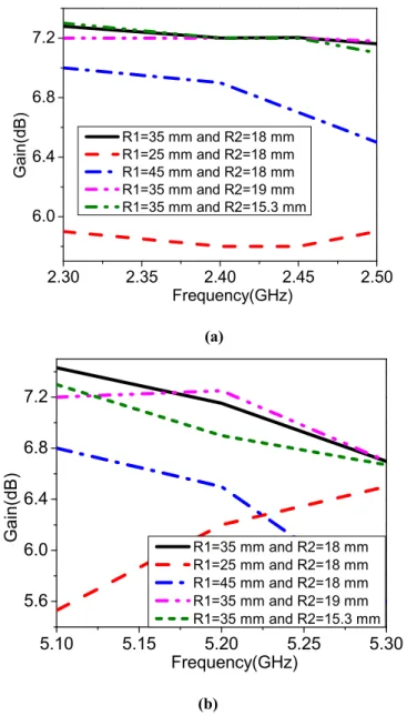
To show the effects of the design parameters on the antenna radiation characteristics, parametric studies are presented in this section. Since the parameters R1 and R2 are the major factors that determine the overall dimensions of the cylindrical AFSS screens, which mainly influence the radiation performance and the gain of the antenna, it is necessary to firstly optimize the periodicities W1 and W3, by which R1 and R2 are defined from Equations 3-1 and 3-2. For simplicity, the DC bias voltage is not taken into account in the following simulations. The values of the parameters W1 and W3 can influence the resonator frequencies of AFSS unit-cells, and hence also influence the radiating characteristics of cylindrical AFSS screens. The effect of W1 on the transmission coefficients of the 2.45 GHz AFSS unit-cell is illustrated in Fig. 3.6 (a) and (b) with the pin-diodes in ON and OFF states, respectively. For the 2.45 GHz AFSS unit-cell, in terms of the reflecting mode (the pin-diode is ON), the resonator frequency at 2.45 GHz is shifted by changing the value of W1, while the value of W1 does not influence the transmission response at 5.2 GHz. In terms of transmitting mode (the pin-diode is OFF), the transmission coefficients do not change too much at 2.45 GHz and 5.2 GHz when the value of W1 changes. When W1 = 36.6 mm and the pin-diode is ON, the resonator frequency of the 2.45 GHz AFSS unit-cell is 2.45 GHz, as shown in Fig. 3.6 (a).
(a)
(b)
Figure 3.6 The effect of the W1 on the transmission coefficients of the 2.45 GHz AFSS unit-cell: (a) pin-diode ON, (b) pin-pin-diode OFF.
2 3 4 5 6 -40 -30 -20 -10 0 Frequency (GHz) T ran smission C o e fficien ts (d B ) W1=26.6 mm(pin-diode ON) W1=36.6 mm(pin-diode ON) W1=46.6 mm(pin-diode ON) 2 3 4 5 6 -40 -30 -20 -10 0 Frequency (GHz) Tra nsm ission C oe fficients (dB) W1=26.6 mm(pin-diode OFF) W1=36.6 mm(pin-diode OFF) W1=46.6 mm(pin-diode OFF)
(a)
(b)
Figure 3.7 The effect of the W3 on the transmission coefficients of the 5.2 GHz AFSS unit-cell: (a) pin-diode ON, (b) pin-pin-diode OFF.
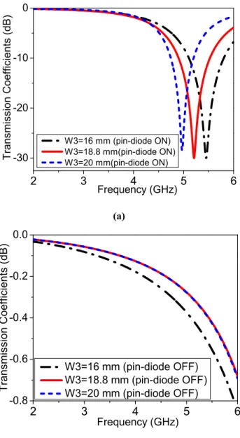
The effect of the W3 on the transmission coefficients of the 5.2 GHz AFSS unit-cell is shown in Fig. 3.7 (a) and (b) with the pin-diodes in ON and OFF states, respectively. For the 5.2 GHz AFSS unit-cell, when the pin-diode is ON, the resonator frequency at 5.2 GHz is shifted by changing the value of W3 but the value of W3 has no effect on the transmission response at 2.45 GHz. When the pin-diode is OFF, the transmission coefficients change slightly at 2.45 GHz and 5.2 GHz when the value of W3 is changed. When W3 = 18.8 mm and the pin-diode is ON, the resonator frequency of the 5.2 GHz AFSS unit-cell is 5.2 GHz, as shown in Fig. 3.7 (a).
2 3 4 5 6 -30 -20 -10 0 Frequency (GHz) Tran smission Co efficients ( dB) W3=16 mm (pin-diode ON) W3=18.8 mm(pin-diode ON) W3=20 mm(pin-diode ON) 2 3 4 5 6 -0.8 -0.6 -0.4 -0.2 0.0 Frequency (GHz) Tran smission Coefficients (d B ) W3=16 mm (pin-diode OFF) W3=18.8 mm (pin-diode OFF) W3=20 mm (pin-diode OFF)
![Figure 1.5 Radiation pattern reconfigurable square spiral microstrip antennas with RF MEMS Switches [36]](https://thumb-eu.123doks.com/thumbv2/123doknet/5006033.124860/20.892.215.679.231.452/figure-radiation-pattern-reconfigurable-square-microstrip-antennas-switches.webp)
![Figure 1.13 A radiation pattern steerable antennas based on AFSS [73], (a) Antenna structure and installation](https://thumb-eu.123doks.com/thumbv2/123doknet/5006033.124860/25.892.194.721.168.721/figure-radiation-pattern-steerable-antennas-antenna-structure-installation.webp)