STUDIU ANALITIC ASUPRA COMPORTĂRII GRINZILOR DIN BETON ARMAT
DEGRADATE DIN CAUZA COROZIUNII CONSOLIDATE CU FRP
ANALYTICAL STUDY ON THE BEHAVIOR OF CORROSION DAMAGED
REINFORCED CONCRETE BEAMS STRENGTHEN WITH FRP
SEDIGHE YOUSEFI MOGHADAM, RAHMAT MADANDOUST , MALEK MOHAMMAD RANJBAR,
MOSTAFA KAZEMI
Department of Civil Engineering, University of Guilan, P.O. Box 3756, Rasht, Iran
The main objective of this study is to numerically investigate rehabilitation of corrosion-damaged reinforced concrete (RC) beams with carbon fiber reinforced polymer (CFRP). In this study, three dimensional (3D) finite element (FE) models for the RC beams, strengthened with FRP sheets, was created. The effect of repairing on corrosion damaged RC beams has been investigated using FRP on load carrying capacity, ultimate deflection and ductility. To achieve these objectives, a beam with average steel mass losses of 31.6% was strengthened with various procedures using CFRP sheet. In addition, a beam with average steel mass losses of approximately 14.2% was strengthened. Results indicate that strengthening of all procedures using FRP sheet increase load carrying capacity and reduce ultimate deflection of the beam. In addition, the effect of strengthening on ultimate load carrying capacity of the beam keeps on increasing with the increase in percentage of corrosion.
Keywords: Carbon fiber reinforced polymer (CFRP), Corrosion, Retrofit, Reinforced concrete (RC) 1. Introduction
Reinforcement corrosion is one of the major causes of deterioration of concrete structures [1], corrosion damages starting from reduction of cross sectional area of steel and reduction of its ductility ending with cracking and bonding problems in the reinforced concrete (RC) elements which leads to the early failure of structures [2]. One of the
promising techniques used recently for
strengthening the damaged structures, for instance, corrosion damaged structure is strengthening with fiber reinforced polymer (FRP). Based on numerical study conducted by Horrigmoe and Hansen [3] on corroded reinforced beams, a good agreement was achieved between test data and the nonlinear finite element (FE) analysis. Reduction in the cross section area due to corrosion of reinforcement and reduction of the bond strength between the corroded reinforcement and concrete were implemented. According to numerical study on concrete beams subjected to corrosion reported by Wang and Chen [4], it was observed that length of
exposed steel reinforcement conclusively
influences rigidity, but it does not affect the strength of concrete beams. In addition, it was found that the decrease in the rebar cross-section is accompanied with a decline in the strength of reinforced concrete members. Xie and Hu [5] experimentally studied the
rehabilitation of corrosion-damaged reinforced concrete beams with carbon fiber reinforced polymer (CFRP). A modified retrofit method, bonding CFRP after replacing V-notch of substrate concrete, was developed. They observed that the modified retrofit method could provide better load carrying capacity and flexural stiffness for the corrosion-damaged beams. Khan et al. [1] investigated a 26-year-old concrete beam exposed to a chloride environment under sustained loading. The result showed that corrosion decreases the ultimate deflection of the beam; in addition, it was observed that the load carrying capacity of the corroded beam was reduced as compared with the non-corroded beam. Țăranu et al. [6] studied the behavior of the interface between carbon fiber reinforced polymer composite plates and concrete. The recorded data have been used to plot the load-slip curves and strains distributions along the composite bonded plates.
The present research investigated the effects of strengthening the corrosion damaged RC beams using externally bonded CFRP sheets on load carrying capacity, ultimate deflection and ductility. Finite element ABAQUS software was used for numerical modeling. A beam with average steel mass losses of 31.6% was modeled and strengthened with various configuration using CFRP sheets. Also to investigate the effect of
Autor corespondent/Corresponding author,
percentage of corrosion reinforcement on the effective of strengthening, a beam with average steel mass losses of 14.2% was modeled. This beam strengthened with FRP and the results were compared with those of a strengthened beam with 31.6% rebar corrosion.
2. Finite element model 2.1. Element types
A finite element model of a concrete beam
was generated using three dimensional
(3D) deformable solid element. The reinforcement bars and stirrups were simulated using 3D deformable wire (truss element), and the shell element was used to model the FRP composite. The embedded region was defined to provide perfect bond between the concrete solid element and the reinforcement element. The constraint of tie was determined the interaction between concrete solid element and FRP composites. 2.2. Materials behavior model
Development of a model for the behavior of concrete is a challenging task. Concrete is a quasi-brittle material and has different behavior in compression and tension. The tensile strength of concrete is typically 8-15% of the compressive strength [7].
In compression, the stress-strain curve for concrete is linearly elastic up to about 30 percent of the maximum compressive strength. Above this point, the stress increases gradually up to the maximum compressive strength. After it reaches the maximum compressive strength σcu , the curve
descends into a softening region, and eventually crushing failure occurs at an ultimate strain εcu . In
tension, the stress-strain curve for concrete is approximately linearly elastic up to the maximum tensile strength. After this point, the concrete cracks and the strength decreases gradually to zero [8]. This model was chosen in the present study.
An elasto-plastic stress-strain relationship was used to describe the stress-strain curve of the steel reinforcement. Poisson’s ratio of 0.3 was considered for the steel reinforcement.
A summary of material properties of composite laminates used for the modeling all strengthened beams is shown in Table 1. Ex, Ey
and Ez are Elastic modulus of the FRP composite
in three directions, Gxy, Gyz and Gxz are Shear
modulus of the FRP composite and νxy, νyz and νxz
are major poisson’s ratio for three planes. Thickness, number of layer and orientation of the fiber direction for each layer are the other parameter needed for modeling the FRP composites in the finite element models.
3. Verification of FE models against experimental results
To verify the FE model of RC beams damaged by rebar corrosion, the experimental study by Maaddawy et al. [10] was used. Figure 1 shows the details of test beam and Table 2 summarizes the experimental program.
To model RC beams damaged by rebar corrosion, the experimental investigation into the residual capacity of corroded reinforcing bars reported by Du et al. [11] was used. They indicated that the cross-sectional area and residual capacity of corroded bars could be determined by Eqs. (1)- (3).
Table 1 Summary of material properties for FRP composites [9]
Thickness of laminate (mm) Shear modulus (MPa) Tensile strength (MPa) Major Poisson’s ratio Elastic modulus (MPa) 1.0 xy
G
= 3270 xzG
= 3270 yzG
= 1860 958 xy
= 0.22 xz
= 0.22 yz
= 0.30 xE
= 62000 yE
= 4800 zE
= 4800 CFRP
Table 2 Summary of the experimental program [10]
percent rebar corrosion Time of corrosion exposure, (days)
specimen - - Virgin 14.2 110 CN-110 31.6 310 CN-310 ( )
(1 0.01
)
s corr corr sA
Q
A
(1) 0(1 0.014
corr)
F
Q
F
(2) 0(1 0.005
corr)
f
Q
f
(1)Where is the average
cross-sectional area of corroded reinforcement, is the initial cross-sectional area of non-corroded reinforcement, is the amount of corrosion of reinforcement steel (%), F: yield or ultimate force of corroded reinforcement, Yield or ultimate force of non-corroded reinforcement, f: yield or ultimate strength of corroded reinforcement, yield or ultimate strength of non-corroded reinforcement. 3.1. Calculations of reinforced concrete beam
with variety percent rebar corrosion CN-110: reinforced concrete beam with 14.2 percent rebar corrosion
( ) (1 0.01 ) (1 0.01 14.2) 188.6 161.819 s corr corr s A Q A (2) ( )
(1 0.005
)
(1 0.005 14.2) 450 418.05
y corr corr yf
Q
f
(3) ( )(1 0.005
)
(1 0.005 14.2) 585 543.46
u corr corr uf
Q
f
(4) CN-310: reinforced concrete beam with 31.6 percent rebar corrosion( )
(1 0.01
)
(1 0.01 31.6) 188.6 129.002
s corr corr sA
Q
A
(5) ( )(1 0.005
)
(1 0.005 31.6) 450 378.9
y corr corr yf
Q
f
(6) ( )(1 0.005
)
(1 0.005 31.6) 585 492.57
u corr corr uf
Q
f
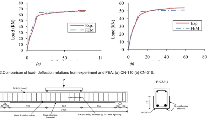
(7) The comparison between the experimental and the FE result for the beams 110 and CN-310 are shown in Figure 2. As can be seen, the obtained load-deflection curves predict the available experimental data satisfactorily.0 10 20 30 40 50 60 70 80 0 50 100
Lo
ad
(K
N
)
Deflection (mm) Exp. FEM 0 10 20 30 40 50 60 0 20 40 60 80 L o ad (K N ) Deflection (mm) Exp. FEM (a) (b)Fig. 2.Comparison of load- deflection relations from experiment and FEA: (a) CN-110 (b) CN-310.
The experimental test, reported by Grace et al. [12], was used to validate the FE model of RC beams strengthened with FRP. Figure 3 shows the details of test beam. The control beam and the beam FCU-1 were selected for verification. The obtained load-deflection curves predict the
available experimental data satisfactorily.
Therefore, it is verified that the finite element analysis can accurately predict the load-deformation curve of the beam strengthened with FRP.
4. Strengthen methods
In this study, the beam with 31.6% rebar corrosion (CB1)was selected from an experimental study reported by Maaddawy et al. [10] that used for validation to investigate the parameters that potentially influence on the behavior of corrosion damaged RC beams strengthened with FRP sheets and one model was kept without strengthening as control specimen. The 28-day compressive strength was 40 MPa. The tensile steel reinforcing bars had yield and ultimate strengths of 450 and 585 MPa, respectively. The 8 mm plain bars used in the compression reinforcement and in the stirrups had yield and ultimate strengths of 340 and 500 MPa, respectively. The main purpose of this study was to investigate the flexural behavior of corrosion damaged RC beams strengthened with externally bonded CFRP sheets and identify the influence of
the design variables considered in the
effectiveness of strengthening. The variables considered in this study include the fiber orientation (parallel, perpendicular and 45 degree to the longitudinal axis of the beam), access to 1 face or 3 faces of the beam for strengthening and continuous wrap or strips. Corrosion-damaged beams were strengthened with 2 layer CFRP sheets at different configurations. Table 3 provides the summary of the parameters and types of strengthening studied. The ultimate tensile strength of epoxy adhesive is 66.2 MPa with an ultimate strain of 4.4% and a compressive strength of 109.2 MPa.
CB1 is the beam with 31.6% rebar corrosion, CB2 is the beam with 14.2% rebar corrosion and VB is the beam without rebar
corrosion. In other beams the first character in the names (H or L) is used to distinguish the high (31.6%) or low (14.2%) percentage of rebar corrosion. In models named as HF and HL, the letter F refers to flexural Strengthen. In models named asHU90Sh, HU90St and HU45St, the letters U refer to U-shape Strengthen, 45 or 90 is used to specify the fiber orientation with respect to the longitudinal axis of the beam, "sh" or "st" is used to specify the type of strengthening schemes such as sheet or strips.
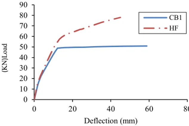
4.1. Strengthen method1 (HF)
In retrofit method1, the Beam HF is strengthened with 2 layers of CFRP that were applied on the bottom face of the beam only. A curve of load against displacement is shown in Figure 4 comparing the non-strengthened beam with 31.6% rebar corrosion (CB1) and the beam with 31.6% rebar corrosion retrofitted by 2 layer of CFRP sheets using retrofit method 2 (HF). Figure 4 shows that the ductility and the ultimate deflection of the strengthened beam decreases by 1.5 and 24 percent, respectively due to brittle characteristics of CFRP laminates. This retrofit method averagely increased in the ultimate load of the beam by 54%, in comparison with CB1.
0 10 20 30 40 50 60 70 80 90 0 20 40 60 80 (K N )L oa d Deflection (mm) CB1 HF
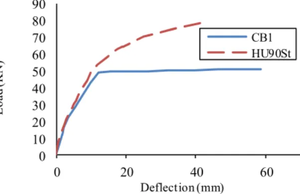
Fig. 4 - Load-deflection curves for beam HF. 4.2. Strengthen method2 (HU90Sh)
The beam HU90Sh is strengthened with 2 layers of U-shape CFRP. A curve of load against displacement is shown in Figure 5 comparing the control beam with 31.6% rebar corrosion (CB1)
Table 3 Summary of test conditions
Specimen name Type of strengthening percent rebar corrosion
VB - -
CB1 - 31.6
HF flexural 31.6
HU90Sh 90 degree, U- wrap 31.6
HU90St 90 degree, U- wrap, strips 31.6 HU45St 45 degree, U- wrap, strips 31.6
CB2 - 14.2
LF flexural 14.2
0 20 40 60 80 100 0 20 40 60 80 L oa d (K N ) Deflection (mm) CB1 HU90Sh 0 10 20 30 40 50 60 70 80 90 0 20 40 60 L oa d (K N ) Deflection (mm) CB1 HU90St
Fig. 5 - Load-deflection curves for beam HU90Sh. Fig. 6 - Load-deflection curve for beam HU90St. and the beam with 31.6% rebar corrosion
retrofitted by 2 layer of CFRP sheets using retrofit method 2 (HU90Sh). Due to brittle characteristics and confining geometry of CFRP laminates, the ductility and the ultimate deflection of the strengthened beam decreased by 2.2 and 34 percent, respectively. This retrofit method averagely increased the ultimate load of the beam by 80%, in comparison with CB1.
4.3. Strengthen method3 (HUC90St2)
The beam HU90St is strengthened with 2 layers of U-shape CFRP strips of 50 mm width and spaced at 50 mm. A curve of load against displacement is shown in Figure 6 comparing the control beam with 31.6% rebar corrosion (CB1) and the beam with 31.6% rebar corrosion retrofitted by 2 layer of CFRP sheets using retrofit method 3 (HU90St). The ductility and the ultimate deflection of the strengthened beam using retrofit method3 decrease by 6 and 27.6 percent respectively, due to brittle characteristics and confined geometry of CFRP laminates. This retrofit method averagely increased the ultimate load of the beam by 55%, in comparison with CB1.
4.4. Strengthen method4 (HU45St)
The Beam HU45St is strengthened with 2 layers of U-shape CFRP strips of 50 mm width and spaced at 50 mm in 45-degree orientation. A curve of load against displacement is shown in Figure 7 comparing the control beam with 31.6% rebar corrosion (CB1) and the beam with 31.6% rebar corrosion retrofitted by 2 layer of CFRP sheets using retrofit method 4 (HU45St). This retrofit method increased in the ultimate load and the ductility of the beam by 72% and 7% respectively
0 10 20 30 40 50 60 70 80 90 100 0 20 40 60 80 L oa d (K N ) Deflection (mm) CB1 HU45St
Fig. 7. Load-deflection curve for beam HU45St.
and decreased in the ultimate deflection of the strengthened beam by 24 percent, compared with CB1.
5. Effect of rebar corrosion level
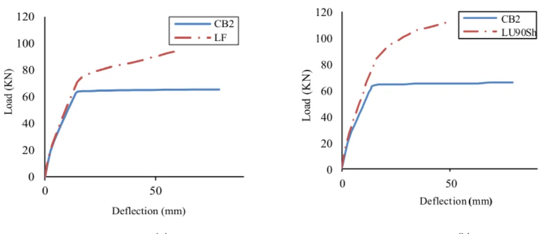
To investigate the effect of rebar corrosion level, a beam with average steel mass losses of 14.2% was strengthened with two layers of CFRP sheets using retrofit method 1 and 2 (Fig. 8). Results were compared with strengthened beam with 31.6% rebar corrosion. Table 4 demonstrate the increase rate of the ultimate loads for the beams with 31.6% and 14.2% rebar corrosion retrofitted by two layers of CFRP sheets using retrofit method 1 (HF and LF) and retrofitted by two layers of CFRP sheets using retrofit method 2 (HU90Sh and LU90Sh). As a result, load carrying capacity of the beams will be different with the changes in the percentage of rebar corrosion; hence, the effect of strengthening on ultimate
Table 4 Summary of model conditions and results
Specimen characteristic HF LF HU90Sh LU90Sh
Increase rate of ultimate
0 20 40 60 80 100 120 0 50 L oa d (K N ) Deflection (mm) CB2 LF 0 20 40 60 80 100 120 0 50 L oa d (K N ) Deflection (mm) CB2 LU90Sh (a) (b)
Fig. 8 - Load-deflection curve for beams with 14.2% rebar corrosion: (a) retrofit method 1 (LF) (b) retrofit method 2 (LU90Sh). load carrying capacity of the beam keeps on
increasing with the increase in percentage of corrosion.
6. Results and discussions 6.1. Load carrying capacity
The effects of various retrofit methods on the load carrying capacity of the corrosion damaged RC beams strengthened with FRP was analyzed. Figure 9 shows the load carrying capacity for the retrofitted beams with two layers of CFRP sheets (HU90Sh, HU45St, HU90St and HF) and the non-strengthened beams (CB1, VB). Figure 9 shows that strengthening of all procedures investigated in this study using CFRP sheets
increased load carrying capacity of the
strengthened beam, compared with control beams including the non-strengthened beam with 31.6% rebar corrosion (CB1) and the non-strengthened beam without rebar corrosion (VB). Compared with flexural method (HF), the U-shape method (HU90Sh, HU45St, and HU90St) through confining beam, Limiting displacement and increasing strengthened area could provide better load carrying capacity for the beam. The experimental study reported by Maaddawy et al. [10] used for validation demonstrated similar result hereof. In addition, Figure 9 shows that the beam strengthened continuously with CFRP laminates in 90-degree orientation (HU90Sh) provided higher ultimate load compared to the beam strengthened with strips of 50 mm width, and spaced at 50 mm (HU90St). It seems that this is due to the effect of more confining of beam HU90Sh as opposed to HU90St.
The Beam strengthened with strips of 50 mm width and spaced at 50 mm with CFRP fibers in 45-degree orientation (HU45St) provided higher ultimate strength compared to the beam HU90St, strengthened with strips having the width of 50 mm and being spaced at 50 mm in 90-degree orien-
tation to the longitudinal axis of the beam. This is due to the effect of installing the FRP with the fiber direction at a 45-degree angle to the longitudinal axis of the beam. Therefore, it can be concluded that when the fiber direction is perpendicular to the crack lines, the effect of strengthening increases bridging of the cracks. The increase in load carrying capacity for the beams reinforced with two layers of CFRP sheet was ranging between 54 percent for flexural strengthening of the corroded beam (HF) and 80 percent for beam strengthened continuously U-Shaped (HU90Sh).
0 20 40 60 80 100 Lo ad ca rr yi ng ca pa ci ty (K N )
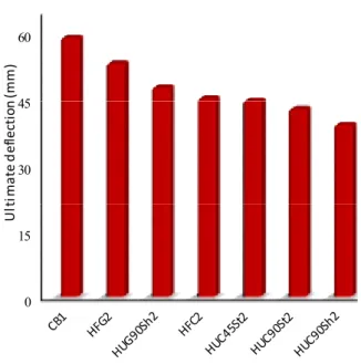
0 15 30 45 60 U lt im at e de fle ct io n (m m )
Fig. 10 - Effects of retrofit schemes on ultimate deflection. 6.2. Ultimate deflection
The effects of various retrofit methods on ultimate deflection of the corrosion damaged RC beams strengthen with FRP was analyzed. Figure 10 shows the ultimate deflection for the retrofitted beams with two layer CFRP sheets (HU90Sh, HU45St, HU90St and HF) and the control beam (CB1). Figure 10 shows that strengthening of all
Fig. 11 - Effects of retrofit schemes on ductility.
procedures using two layers of CFRP sheets reduces ultimate deflection of the strengthened beam compared with control beam due to brittle characteristic of FRP laminates. This reduction in ultimate deflection was ranging between 34 percent for beam shear strengthened continuously U-Shaped by CFRP (HU90Sh) and 24 percent for beam strengthened flexural by CFRP (HF).
6.3. Ductility
To compare the effects of various retrofit methods on ductility of the corrosion damaged RC beams strengthen with FRP, ductility for the retrofitted beams with two layers CFRP (HU90Sh, HU45St, HU90St and HF) and the control beam (CB1) is shown in Figure 11. Retrofit method 4 provided better ductility than all of other methods. Strengthening with CFRP sheet U-shaped diagonal to the direction of the longitudinal beams (HU45St) unlike other methods (HF, HU90Sh and HU90St) increase the ductility of the beam. So it seems that this reinforcement technique can be appropriate to achieve the purpose of increasing the load carrying capacity of the beam without having reduced a great deal of ductility of the beam.
The results of the different studies strongly suggest that the corrosion cracking around the steel rebar is a fundamental component contributing to the loss of structural strength. This implies that if corrosion cracking can be prevented, or at least decreased, a certain degree of structural strength may be maintained in a corroding RC beam [12]. The PE, Max principal pattern demonstrates the main plastic strain which is the best criterion to assess the maximum tensile failure (cracking). Figures 12 and 13 show that the U-shape method (HU90Sh) could decrease plastic strains more than flexural method (HF) for the strengthened beams.
(a) (b)
Fig. 13 - The distribution of plain strain for: (a) Strengthen method1 (HF) (b) Strengthen method2 (HU90Sh). 7. Conclusions
In this paper, finite element analysis of reinforced concrete beams strengthened with CFRP sheets was performed. Based on the numerical results, the findings support the following conclusions:
There was a good agreement between finite element analysis and experimental work.
All strengthening configurations, applied in this paper using FRP sheets, increased load carrying capacity of the beam compared with control beams either without rebar corrosion or with 31.6% rebar corrosion.
The increase in load carrying capacity for the beams strengthened with two layers of CFRP sheet and different configuration was ranging between 54 percent (for beam strengthened flexural) and 80 percent (for beam shear strengthened continuously U-Shaped).
Compared with flexural method, the U-shape method could provide better load carrying capacity for the beam with 31.6% mass loss of steel.
All strengthening configurations, applied in this paper using FRP sheets, reduced ultimate deflection of the beam compared with control beams either without rebar corrosion or with 31.6% rebar corrosion.
The decrease in ultimate deflection of the beams strengthened with two layers of CFRP sheet and different configuration was ranging between 34 percent (for beam shear strengthened continuously U-Shaped) and 24 percent (for beam strengthened flexural).
Strengthening with CFRP sheet U-shaped diagonal to the direction of the longitudinal beam provided better ductility than all of other methods. This method unlike other methods (HF, HU90Sh, and HU90St) increases the ductility of the beam.
Load carrying capacity of the beams will be different with the change in the percentage of rebar corrosion. The effect of strengthening on ultimate load carrying capacity of the beam keeps on increasing with the increase in percentage of corrosion.
REFERENCES
1. I. Khan, R. François and Arnaud Castel, Structural performance of a 26-year-old corroded reinforced concrete beam, European Journal of Environmental and Civil Engineering, 2012, 16(3-4), 440.
2. B. Almassri, A. Kreit, F. Al Mahmoud and R. Francois, Mechanical behavior of corroded RC beam strengthened by NSM CFRP rods, Composites Part B: Engineering, 2014, 64,97.
3. G. Horrigmoe and T. Hansen, Assessment of the performance of structures attacked by reinforcement corrosion, International RILEM Symposium on Advances in concrete Through Science and Engineering, Northwestern University, Evanston, Illinois, March 22-24, 2004.
4. W. L. Wang and J. Chen, Residual Strengths of Reinforced Concrete Beams with Heavy Deterioration, Research Journal of Applied Sciences, Engineering and Technology, 2011, 3(8), 798.
5. J. Xie, R. Hu, Experimental study on rehabilitation of corrosion-damaged reinforced concrete beams with carbon fiber reinforced polymer, Construction and Building Materials, 2012, 38, 708.
6. N. Taranu, R. Cozmanciuc, I. Entuc, M. Budescu, V. Munteanu, D. Isopescu, The behavior of the interface between carbon fiber reinforced polymer composite plates and concrete, Romanian Journal of Material, 2015, 45(3), 232.
7. S. P. Shah, S. E. Swartz and C. Ouyang, Fracture Mechanics of Concrete, John Wiley & Sons, Inc., New York,1995.
8. M. Y. H. Bangash, Concrete and Concrete Structures: Numerical Modeling and Applications, Elsevier Science Publishers Ltd., London, England, 1989, 22(15).
9. D. Kachlakev, T. Miller, S. Yim, K. Chansawat and T. Potisuk, PhD thesis, Finite element modelingof reinforced concrete structuresstrengthened with FRP laminates, Final Report SRP 316, Oregon State University Department of Transportation, 2001.
10. T. Maaddawy, K. Soudki and T. Topper, Long-term performance of corrosion-damaged reinforced concrete beams, ACI Structural Journal, 2005, 102 (5), 649. 11. Y. G. Du, L. A. Clark and A. H. C. Chan, Residual capacity
of corroded reinforcing bars, Magazine of Concrete Research, 2005, 57(3), 135.
12. N. F. Grace, W. F. Ragheb and George Abdel-Sayed, Flexural and shear strengthening of concrete beams using new triaxially braided ductile fabric, ACI Structural Journal, 2003, 100(6), 804.
![Table 1 Summary of material properties for FRP composites [9]](https://thumb-eu.123doks.com/thumbv2/123doknet/5654857.137004/2.892.123.758.764.1114/table-summary-material-properties-frp-composites.webp)