HAL Id: hal-01102409
https://hal.archives-ouvertes.fr/hal-01102409
Submitted on 12 Jan 2015HAL is a multi-disciplinary open access archive for the deposit and dissemination of sci-entific research documents, whether they are pub-lished or not. The documents may come from teaching and research institutions in France or abroad, or from public or private research centers.
L’archive ouverte pluridisciplinaire HAL, est destinée au dépôt et à la diffusion de documents scientifiques de niveau recherche, publiés ou non, émanant des établissements d’enseignement et de recherche français ou étrangers, des laboratoires publics ou privés.
Creation of a gradient index structure inside foam
material - Microwave application for a lens antenna at
60 GHz
Jonathan Bor, Olivier Lafond, Mohamed Himdi
To cite this version:
Jonathan Bor, Olivier Lafond, Mohamed Himdi. Creation of a gradient index structure inside foam material - Microwave application for a lens antenna at 60 GHz. Microwave Symposium (IMS), 2014 IEEE MTT-S International, Institute of Electrical and Electronics Engineers ( IEEE ), pp.1 - 4, 2014, 9781479938704. �10.1109/MWSYM.2014.6848330�. �hal-01102409�
Creation of a gradient index structure inside foam material –
Microwave application for a lens antenna at 60 GHz
J. Bor
1, O. Lafond
1and M. Himdi
11
Institute of Electronic and Telecommunications of Rennes
Abstract — Creating a gradient index into a dielectric structure is a major issue nowadays for the design of microwave components and antennas, especially for inhomogeneous lenses as Luneburg, Fresnel and Maxwell Fish-eye. The use of a foam material and a simple technological process can allow this. Because a foam material is composed of air bubbles, and core materials (resin, PVC, …), removing the air will increase the density of the foam and so increase its dielectric constant. The authors present a simple technological process to expel the air from a piece of foam in order to increase the permittivity of the foam. This is then applied to the design of a Luneburg lens antenna at 60 GHz.
Index Terms — Characterization, controlled dielectric constant, foam material, gradient index, Luneburg lens, microwave.
I. INTRODUCTION
Materials with controllable permittivity are mainly used for electromagnetism applications. Foam is a composite material and exists with numerous dielectric constants [1, 2]. It can be used as a mechanical support or directly to design millimeter circuits or antennas as a substrate [3]. The foam material used in [3] provides a low dielectric constant (close to 1). It allows to design antennas with high efficiency. This type of foam is based on PVC material. For microwave applications, substrate integrated non radiative waveguides can be manufactured with a specific dielectric constant [4]. Antennas with inhomogeneous lenses can be designed at millimeter waves to focus the radiation pattern [5, 6, 7] but such lenses (Fresnel-zone plate lens, Luneburg lens, Maxwell fish-eye lens and Rotman lens) require the use of materials with different dielectric constants. For these kinds of lenses, the aim is to reduce the cost by using only one material with a controlled dielectric constant in order to simplify the manufacturing. The authors investigate a new and simple technological process [8] to control the dielectric constant of a basic foam material. By expelling the air contained inside a foam slab, the dielectric constant can be increased and controlled.
In the second part, the technological process is explained in details. The third part describes the measurement setup of dielectric constant. The results of characterization are shown to validate the principle of controlled dielectric constant based on one initial foam material. These experimental results are compared to theoretical data allowing the prediction of the dielectric constant. In the last part, an application of flat
Luneburg lens is presented and measurements are compared to the simulation results at 60 GHz.
II. INCREASINGDIELECTRICCONSTANTPROCESS
A. Foams overview
Four different foams from two suppliers are studied in this paper in order to validate the process:
- H 200 and HCP 50 from Divinycell [1]
- Airex PXc 245 and Airex PXc 320 from Corematerial [2]
These foams are closed cell foams and are mainly used in the construction field because of their mechanical properties.
The four foams have been measured with a free space bench to determine their permittivity and losses. The results are shown in Table 1.
I. TABLE 1
II. MEASURED ELECTRICAL PROPERTIESOFTHE FOAMSAT 60
GHZ
Foam type εr tan δ
H 200 1.23 0.005
HCP 50 1.31 0.004
Airex PXc 245 1.31 0.010
Airex PXc 320 1.43 0.014
The main idea of increasing the dielectric constant of a foam sample is to change the ratio between the air and the core materials. Indeed, the permittivity of a sample is determined by the density of its components and their volumes. Two different formulas will be reviewed and compared to measurement.
B. Pressing process
To expel the air of a sample, a simple pressing process is implemented. The foam material sample has to be pressed at a fixed temperature depending of the material. In this experiment, 90°C is chosen in order to not alterate the foam characteristics. It allows the sample to be fixed after being pressed. If the temperature is not high enough, the sample can “uncompress” and the air goes back into the sample. At the same time, if temperature is too high, the sample might be burned. A similar result is observed with the duration of pressure. It has to be long enough for the sample to be homogeneous in term of temperature. In this case, 20 minutes
is sufficient. A picture of an H 200 foam sample before and after being pressed is featured Fig. 1 and Fig. 2 to illustrate the results.
Fig. 1. Stepped sample before the pressing process (5, 10, 15mm thick)
Fig. 2. Stepped sample after the pressing process at 5mm
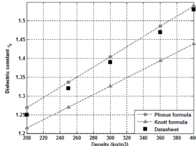
After the pressing process, sample can be measured in order to determine the permittivity and the results are shown in the next part. It is further possible to predict the dielectric constant of a sample. For that purpose, two theoretical methods are used: Knott [9] and Plonus [10]. By knowing the density of the combination of core materials (all components of the foam except air) and its permittivity, the authors are able to calculate the permittivity of a pressed foam sample. To determine this density and permittivity, a piece of foam is powdered before the pressing process. The measurement will allow the authors to have the utmost density (ρp) and
permittivity (εp) that correspond to those of the combination of
polymers. With these values (given in Table 2), the dielectric constant of a foam sample (εf) can be predicted with the help
of the Knott formula (1). It depends on the permittivity of the polymer (εp), the air (εa), and the ratio α between the density of
the foam and the density of the polymer.
ε
f=
ε
p1−
(
ε
p−
ε
a)
(
1−α
)
ε
a+
(
ε
p−
ε
a)
(
1−α
)
13 (1)
Moreover, Plonus found another formula based on the ratio of the volume of air and the volume of polymer (2). ξ represents the density ratio and ρfi the density of the foam
before the pressing process.
V
aV
p=
ρ
p−
ρ
fiξ ρ
fiξ − ρ
a (2)With this formula, the dielectric constant can be calculated:
ε
f=
V
aV
p∗
ε
a+
ε
pV
aV
p+1
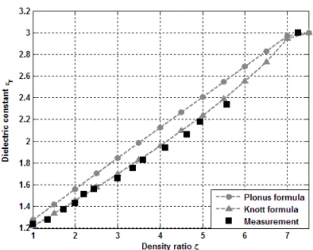
(3)Both formulas are compared to data sheet for Divinycell foams on Fig. 3 and 4. It shows a good agreement.
III. TABLE 2
IV. DENSITYANDDIELECTRICCONSTANTOFTHEDIFFERENT BASICFOAMPOLYMERSMEASUREDAT 60 GHZ (AFTER
REMOVINGALLAIR)
Material type ρ εr
H 200 1600 kg/m3 3
HCP 50 1500 kg/m3 2.92
Airex PXc 245 1075 kg/m3 2.8
Airex PXc 320 1273 kg/m3 3.15
Fig. 3 Dielectric constant law versus density ratio for H foam
Fig. 4 Dielectric constant law versus density ratio for HCP foam
III. FREESPACEMEASUREMENT
A free space bench is performing the dielectric constant measurement [11, 12]. The bench is made of two horn-lenses antenna to focus the signal in the sample under test. An ABmm Vector Network Analyzer will process the S21 parameter (amplitude and phase). Results are computed [13, 14] to extract the permittivity and losses of the sample.
The measurement is performed in the V-band (50-75 GHz), and the results are given at 60 GHz (frequency is chosen for the application presented in the last part).
The free space measurements of the four different samples (Fig. 5, 6, 7 and 8) are compared to the both theoretical
methods of Knott and Plonus. It demonstrates a good behavior. The results show that dielectric constant can range from 1.31 to 2.8 for Airex PXc 245 (the one that will be used in the next part). Both Airex foams provide a better stability. Indeed, for Divinycell foams, the surface of samples increases during the pressing process when a mold is not used. It is due to the glass fiber reinforcement inside Airex PXc foams.
Fig. 5. Dielectric constant law versus density ratio for H 200 foam
Fig. 6 Dielectric constant law versus density ratio for HCP 50 foam
Fig. 7. Dielectric constant law versus density ratio for PXc 245 foam
Fig. 8 Dielectric constant law versus density ratio for PXc 320 foam
IV. APPLICATION(S)
Based on previous measurements, Airex PXc 245 has been chosen because of its range of permittivity that starts lower than PXc 320 (εr=1.41). A Luneburg lens with a gradient index
inside is designed at 60 GHz. The dielectric constant must follow the radial law given in (4).
n
(
r
)
=
√
ε
r=
√
2−r²
(4)With “r”, the normalized radius. It is calculated by the ratio of the actual position inside the lens and the radius of the lens. This particular law provides an infinity of focal points around the lens and a plane wave at the opposite. It will thus focus the signal at the output of the lens. The lens is made of 6 areas [15], one area with a ring of Rohacell foam (εr1=1.05) and five
areas made of one piece of foam (εr2=1.31, εr3=1.46, εr4=1.62,
εr5=1.77 and εr6=1.92). It is pictured before and after the
pressing process on Fig. 9.
(a) (b)
Fig. 9. Luneburg lens (a) before and (b) after the pressing process
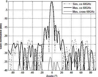
This lens is fed by a classical open-ended WR15 waveguide. In terms of radiating patterns, the antenna was afterwards measured in an anechoic chamber between 57 GHz and 65 GHz and the results in the H-plane are shown in Fig. 10 at 60 GHz. The antenna has a half-power beamwidth of
5.2° (and 52.5° in the E-plane) with side lobe level under -14 dB. The results show a good agreement between simulation and measurement and validate the technological process The measured gain increases from 15.5 dBi to 17 dBi. The loss efficiency (Fig. 11) is stable at 65% between 57 GHz and 65 GHz..
Fig. 10. Simulation versus measurement of the Luneburg lens in H-plane at 60 GHz
Fig. 11. Simulated directivity, measured gain and loss efficiency between 57 GHz and 65 GHz
V. CONCLUSION
A technological process to create a gradient index inside a foam material has been presented in this article. The process has been validated by the measurement of a gradient index lens at 60 GHz. It is simple, lightweight and inexpensive. The process is limited by the range of permittivities, depending on the material used.
This technological process can be applied to the design of microwave components and antennas and makes the manufacturing of gradient index structure much easier. More results will be given in the conference as a near-field focusing antenna and a Mikaelian lens.
REFERENCES
[1] Divinycell, www.diabgroup.com.
[2] Airex Baltek, http://www.corematerials.3acomposites.com/
[3] S. Chainon, “Etude et conception d’antennes composes de guides d’ondes en technologie mousse métallisée. Applications aux antennes à balayage électronique,” Dissertation at the
University of Rennes 1, France, 2002.
[4] F. Xu, K. Wu, “Substrate Intergrated Nonradiative Dielectric Waveguide Structures Direcly Fabricated on printed Circuit Boards and Metalized Dielectric Layer,” IEEE Transactions on
Microwave Theory and Techniques, Vol. 59, No 12, December
2011.
[5] H. D. Hristov, H. A. J. Herben, “Millimeter-wave Fersnel-zone plate lens and antenna,” IEEE Transactions on Microwave
Theory and Techniques, vol. 43, no. 12, Dec. 1995
[6] B. Fuchs, O. Lafond, S. Palud, L. Le Coq, M. Himdi, M. C. Buck and S. Rondineau, “Comparative Design and Analysis of Luneburg and Half Maxwell Fish-Eye Lens Antennas,” IEEE
Transactions on Antennas and Propagation, vol. 56, no. 9, Sept.
2008.
[7] L. Schulwitz, A. Mortazawi, “A new low loss Rotman lens design using a graded dielectric substrate,” IEEE Transactions
on Microwave Theory and Techniques, Vol. 56, No. 12, Dec.
2008.
[8] H. Merlet, P. Le Bars, O. Lafond, M. Himdi, “Manufacturing method of a dielectric material and its application to millimeter-waves beam forming antenna systems,” patent WO2013083794, June, 2013.
[9] E. F. Knott, “Dielectric constant of plastic foams,” IEEE
Transactions on Antennas and Propagation, Vol. 41, No. 8, pp.
1167-1171, August 1993.
[10] M. A. Plonus, “Theorical investigations of scattering from plastic foams,” IEEE Transactions on Antennas and
Propagation, Vol. 13, no. 1, pp. 88-94, January 1965.
[11] G. L. Friedsam and E. M. Biebl, “A Broadband Free-Space Dielectric Properties Measurement System at Millimeter Wavelengths,” IEEE Transactions on instrumentation and
Measurement, Vol. 46, No. 2, April, 1997.
[12] ABmm on http://www.abmillimetre.com/.
[13] D. Bourreau, A. Péden and S. Le Maguer, “A Quasi-optical Free-Space Measurement Setup Without Time-Domain Gating for Material Characterization in the W-Band,” IEEE
Transactions on Instrumentation and Measurement, Vol. 55, No.
6, December 2006.
[14] D. K. Ghodgaonkar, V. V. Varadan and V. K. Varadan, “Free-Space Measurement of Complex Permittivity and Complex Permeability of Magnetic Materials at Microwave Frequencies,”
IEEE Transactions on Instrumentation and Measurement, Vol.
39, No. 2, April 1990.
[15] B. Fuchs, L. Le Coq, O. Lafond, S. Rondineau and M. Himdi, “Design optimization of multishell Luneburg lenses,” IEEE
Transactions on Antennas and Propagation, Vol. 55, No. 2,