HAL Id: hal-01295439
https://hal.archives-ouvertes.fr/hal-01295439
Submitted on 31 Mar 2016HAL is a multi-disciplinary open access archive for the deposit and dissemination of sci-entific research documents, whether they are pub-lished or not. The documents may come from
L’archive ouverte pluridisciplinaire HAL, est destinée au dépôt et à la diffusion de documents scientifiques de niveau recherche, publiés ou non, émanant des établissements d’enseignement et de
A multi-order probabilistic approach for Instantaneous
Angular Speed tracking. debriefing of the CMMNO’14
diagnosis contest
Quentin Leclere, Hugo André, Jérôme Antoni
To cite this version:
Quentin Leclere, Hugo André, Jérôme Antoni. A multi-order probabilistic approach for Instantaneous Angular Speed tracking. debriefing of the CMMNO’14 diagnosis contest. Mechanical Systems and Signal Processing, Elsevier, 2016, �10.1016/j.ymssp.2016.02.053�. �hal-01295439�
A multi-order probabilistic approach for
Instantaneous Angular Speed tracking
debriefing of the CMMNO’14 diagnosis
contest
Quentin Lecl`ere
a,∗ Hugo Andr´e
bJ´erˆome Antoni
aaLaboratoire Vibrations Acoustique, INSA Lyon, 25 bis avenue Jean Capelle
F-69621 Villeurbanne Cedex, FRANCE
b
Maia Eolis,Tour de LILLE (19 ´etage) Bd de Turin 59777 Lille, FRANCE
Abstract
The aim of this work is to propose a novel approach for the estimation of the Instan-taneous Angular Speed (IAS) of rotating machines from vibration measurements. This work is originated from the organisation, by the authors of this paper, of a contest during the conference CMMNO 2014, that was held in Lyon, december 2014. One purpose of the contest was to extract the IAS of a wind turbine from a gearbox accelerometer signal. The analysis of contestant contributions led to the observation that the main source of error in this exercise was the wrong association of one se-lected and tracked harmonic component with one mechanical periodic phenomenon, this association being assumed as an a priori hypothesis by all the methods used by the contestants. The approach proposed in this work does not need this kind of a priori assumption. A majority (but not necessarily all) periodical mechanical events are considered from a preliminary analysis of the kinematics of the machine (harmonics of shaft rotation speeds, meshing frequencies ...). The IAS is then deter-mined from probability density functions that are constructed from instantaneous spectra of the signal. The efficiency and robustness of the proposed approach are illustrated in the frame of the CMMNO 2014 contest case.
Key words: Instantaneous Angular Speed, wind turbines, order tracking,
demodulation, virtual tacho
∗ Corresponding author. Fax: 33.4.72.43.87.12. E-mail address:
Nomenclature
Ω: IAS (Instantaneous Angular Speed) (in Hz)
ω: argument of the probability density function (pdf) of the IAS (in Hz) A(f ): whitened instantaneous spectrum (dimensionless), depending on the
fre-quency f (in Hz)
Ωmin: minimum value of the a priori IAS uniform law (in Hz) Ωmax: maximum value of the a priori IAS uniform law (in Hz)
Hi (i ∈ [1...n]): orders of the mechanism, with respect to the IAS (dimension-less)
[Ω|Hi]: pdf of the IAS knowing Hi, function of ω (in Hz)
[Ωj|Ωj+k]: pdf of the IAS at time j knowing the IAS at time j + k, function of ω (in Hz)
[Ωj]j+k: pdf of the IAS at time j obtained from [Ωj+k], function of ω (in Hz)
γ: standard acceleration for IAS (smoothing parameter), in (Hz2
) [Ωj]s: smoothed pdf of the IAS at time j, function of ω (in Hz)
1 Introduction
In many aspects, the Instantaneous Angular Speed (IAS) is to the Condi-tion Monitoring of rotating machines what the heartbeat signal is to medicine. Just as in medicine, the IAS provides vital information for diagnosis and it allows resynchronization of subsequent analyses.
The importance of the IAS and of its measurement has been addressed in a recent special issue of MSSP [1,2] and in a review paper [3]. Its use for order tracking is also discussed in the review paper [4].
As indicated by the adjective instantaneous, the IAS is a measure of the rota-tion speed of a rotating component in a machine with an angular resolurota-tion that corresponds to at least one value per revolution. The IAS enters as an essential ingredient to several processing techniques dedicated to the analysis of machines operating under nonstationary regimes.
It has been for long an essential quantity in rotor dynamics and in NVH appli-cations concerned with the testing of rotating machines in transient regimes such as runups and shutdowns. In this context, the IAS makes possible the synchronization of Fourier analysis on the shaft rotation – a practice known as order (spectral) analysis – or the tracking of the evolution of the Fourier coefficients as a function of speed - a practice known as order tracking [5–7]. Early successes of order tracking are exemplified by the Vold-Kalman filter [8–14], a model-based approach well suited to slow-speed variations and high SNRs. It is traditionally accepted that order analysis and order tracking ap-ply to deterministic signals which exhibit (modulated) harmonic structures in the order domain. It is only recently that these ideas have been extended to broadband signals. A typical example is provided by the vibrations of bearings
under nonstationary regimes, where order analysis has been successfully ap-plied to the signal envelope or to time-frequency energy distributions [15–17]. The IAS also turns out essential to resample machine signals in the angular domain in all applications where synchronization to the machine kinematics is essential to correctly identify and analyze transient events in the machine cycle [18–20].
The advantage of synchronizing signals to the angular domain has been fully highlighted within the cyclostationary framework, where the notion of ma-chine cycle is central [21,22]. The cyclostationary framework happens to per-fectly model most signals produced by rotating machines operating under stationary regimes. The latter condition has recently been extended to non-stationary regimes, thus generalizing the cyclonon-stationary class of signals to the cyclononstationary class. One important contribution of the cyclononsta-tionary framework is to extend the principles of order analysis to any type of signal, including both deterministic and random types. In that context, the IAS constitutes a fundamental variable for their description [23,24].
The IAS is not only useful as a reference signal; just as the heartbeat signal in medicine, it may serve as a diagnostic quantity per se. This has been early recognized for the diagnostic of electric motors and of internal combustion en-gines [25–27] for instance and, more recently and perhaps more surprisingly, for the diagnosis of rolling element bearings [28,29]. Research is also ongoing to use the IAS for the monitoring of machining processes [30], in which case it directly reflects the cutting forces.
The measurement of the IAS is ideally achieved by a tachymeter mounted on the machine. There exists various technologies, such as angular accelerometers or coder-based devices. In turn, the signals are either directly sampled in the angular domain by using the tachymetric signal as an external clock to the ADC or aposteriori resampled by using digital processing algorithms. The lat-ter strategy is sometimes referred to as compulat-ter order tracking. These aspects are discussed in Refs. [31–35,5]. Technological aspects of the measurement of the IAS and associated errors are further investigated in Refs. [36–39,29,40– 42].
The provision of a tachymeter with sufficient resolution is not always possi-ble for technological or cost reasons. In these situations, endeavors have been made to recover the IAS from the machine signals (e.g. vibrations). This is a most difficult situation, yet of major interest since it does not require any specific instrumentation and potentially returns the exact IAS of interest (e.g. the IAS used for subsequent resampling of the machine signals). One of the first successful attempt towards this direction is probably the non-parametric approach based on complex envelope demodulation proposed in Ref. [14] and further refined in Ref. [43]. It applies to low speed fluctuations characterized by a narrow-band spectrum as compared to the carrier frequency. Follow-ing this impetus, several demodulation methods have been proposed durFollow-ing the last six years in order to extract the IAS from complex vibration signals in more general scenarios [44,15,45,46]. Model-based (e.g. Kalman filter)
ap-proaches demonstrate good accuracy [47–49], yet a patent limitation is that all harmonics have to be modeled – even those which are not of interest -so as to produce a Gaussian residual. An important body of literature has also addressed the problem by using tailored time-frequency decomposition such as the Gabor transform and wavelet transforms [50–55]. The variety of approaches that have been proposed so far reflects the inherent difficulty of the problem. One difficulty actually stems from the multi-component nature of the signals where different families of harmonics may coexist, each being characterized by numerous components (several tens or hundreds of harmon-ics are commonplace in some applications). Another difficulty stems from the interaction between the orders and the structural resonances of the machine. One last difficulty is to operate under low SNRs as is typically the case with vibration signals (the noise being understood as any component in the signal which is not of direct interest for the analysis). All these challenges jeopardize the application of standard signal processing tools dedicated to instantaneous frequency estimation [56–59] and ask for a specific approach.
In the presence of multi-component signals, it is actually advantageous to track all harmonics jointly instead of individually as is proposed by most of the methods of the state-of-the-art. Since more information is considered at once, the estimation of the IAS is expected to gain in accuracy. At the same time, a gain in robustness is also envisioned in scenarios where some of the harmonics happen to fade or cross with other families. It is specifically the object of this paper to propose a multi-harmonic tracking method.
The present work finds its origins in the organization, by its authors, of a con-test during the The fourth International Conference on Condition Monitoring of Machinery in Non-Stationary Operations (CMMN0 2014). Contestants were asked to extract an IAS from the vibration signal of a wind turbine’s gearbox. The first section of this paper is dedicated to a debriefing of this contest. The analysis of contributions, also discussed in the first section, led the authors of the present work to propose an innovative approach for blind IAS estimation, based on a probabilistic formalism: this is the object of the second section. The third section illustrates the efficiency of the method, in the frame of the CMMNO’14 contest signals.
2 CMMNO 2014 diagnosis contest
The fourth International Conference on Condition Monitoring of Machinery in Non-Stationary Operations (CMMN0 2014) was held in Lyon (France) on the 15th and 16th of December 2014. More than one hundred people attended this event, from university and industry, among which several international level experts in the field of rotating machine monitoring. Several months before the event, a diagnosis contest was launched: a signal, as well as some kinematic data were provided to participants. The aim of the contest was to estimate the IAS of the rotating machine, and to propose a diagnosis of potential faults.
The contestants had to send back the estimation of the instantaneous speed, as well as a diagnostic report, a few weeks before the start of the conference. 23 people registered to the contest, but only 8 contributions from 7 different countries have been received in due form by the Organization Committee. The results were presented during the afternoon plenary session of the 16th of December, and the first prize was awarded to Bob Randall, Michael Coats and Wade Smith (University of new south Wales, in Sidney). They provided the best estimation of the IAS, as compared to a reference that was directly measured with an angle encoder. The next section briefly resumes the case study addressed during the contest.
2.1 The case study: a wind turbine gearbox signal
Though gearbox defects appear to be 50% less frequent than electric system faults, the main cause of overall wind turbine downtime is related to gearbox faults, as is can be seen in Fig. 1 and according to WindStats database anal-ysis focused on more than 30000 wind turbines [60]. This fact simply shows that these occurrences are longer to be dealt with. However, bearing or even gearbox replacement never exceeds a few days. Most of the time is actually spent to order new components, manufacture and bring them on site along with available technicians. In case cranes are needed, extra time must be spent preparing the platform and bringing a crane on site, which can be as long as obtaining a spare bearing. Hence, improving condition monitoring system abil-ity to detect gearbox fault as soon as possible allows limiting turbine downtime to the duration of the replacement itself.
Although vibration monitoring benefits from wide academic and industrial experiences, most of the works are focused on time based methods. Indus-trial equipments are therefore mainly dedicated to time based observations and these simple systems are widely used in the wind industry for economical reasons. Inherently relying on unsteady operating conditions, wind turbines nevertheless presents the particularity to produce strongly non stationary mea-surements. Rotating speed and operating torque are constantly fluctuating and the use of angle domain observations seems unavoidable. This shows the neces-sity to propose an approach based on time based acquisition system to tackle non stationary problems. In particular, this paper focuses on a new method to resample the signal in the angle domain without the use of complex hardware or even a tachymeter.
Common to any wind turbine gearbox vibration signal are 3 kinds of periodic phenomena:
• Time dependent phenomena produced by subsystems such as the converter chopper frequency, the electric gear pump to help lubricant flow through the system, the heat exchanger fan, the natural frequencies of the structure (tower, blades, gearbox housing ...)
pro-Fig. 1. Wind stat data base, 2008-2012 aggregated downtime per turbine system[60].
duced mainly by gears and shafts unbalance. These phenomena have a fun-damental frequency in constant ratio with the high speed shaft.
• Other phenomena such as those produced by the slip frequency of the asyn-chronous generator, and the yaw gearbox system (used to rotate the nacelle in the wind direction). These are neither time stationary (they depend on rotor angular speed for the first one and on resisting torque for the second one) nor angle stationary (they are not proportionally linked with angular speed).
The signal is polluted by different sources of noise which all share the charac-teristic of not being angle dependent. Angular domain analysis will therefore not only focus on the observation on gearbox-kinematic dependent phenom-ena, but it will also blur all phenomena that are not steady in the angle domain as soon as the rotating speed varies.
In the CMMNO contest, the signals are recorded with IFM-Eletronics VSE002 acquisition systems, sampled at 20kHz and quantified with a 12bits resolution. An accelerometric sensor is located on the gearbox housing, in the vicinity of the epicyclic gear train. A fault is located on the inner ring of planet bearing C (see Fig 2) and introduces an angular periodic impulsive phenomenon at 0.191 high speed shaft orders in the signal.
2.2 Analysis of the contributions of the contestants
The contestants were asked to provide an estimation in the angular domain of the rapid shaft IAS (carrying gear # 7 in Fig. 2), with a resolution of 8
Fig. 2. CMMNO 2014 contest: Kinematic data of the gearbox.
samples by rotation. Results were compared to the reference speed directly measured with an angle encoder. All IASs (estimations and reference) were resampled in the time domain to ease the comparison. They are displayed in Fig. 3. It is clear from this figure that the results provided by the contestants are strongly dispersed around the reference (±15%), even if the general shape is correctly obtained. 50 100 150 200 250 300 350 400 450 500 16 18 20 22 24 26 28 30 32 time (s) IAS (Hz) 50 100 150 200 250 300 350 400 450 500 −15 −10 −5 0 5 10 15 time (s) Error (%)
Fig. 3. Results of the CMMNO 2014 contest. Left: estimated IASs compared to the reference (solid blue), right: relative error with respect to reference.
Different techniques were employed by the contestants to extract the IAS from the vibration signal, which can be classified in two families:
• single harmonic tracking in the time-frequency map,
• narrow-band filtering around one selected harmonic followed by instanta-neous phase demodulation.
The winning team used a method belonging to the second family (see [46] for details). However, the reason of their success is less related to the method they used than to their ability to associate the selected harmonic to the cor-rect periodic event of the kinematics. Indeed, all contestant have used more or less sophisticated techniques allowing the fine tracking of one given
har-monic in the signal, but only the winning team has correctly associated this harmonic to the right phenomenon. This is the reason why the general shape of the IAS obtained by the contestants is correct (efficient tracking of the in-stantaneous frequency of the selected harmonic), yet with a scaling error due to the association to a wrong mechanical component. The difficulty of this second task is explained in the present case by the relative complexity of the provided signal : about 50 harmonics are clearly visible in the time frequency map (see Fig. 6 in section 4). Among these numerous harmonics, some hap-pen to be related to mechanical elements that are not included in the main kinematic data provided for the contest. For instance, the strong harmonic starting at about 650Hz at t = 0 in the time-frequency map (Fig. 6), which is one of the strongest components is the signal, is not related to the main meshing frequencies of the gearbox. Moreover, it is important to note that it is not strictly a multiple of the rotation frequency, which is probably due to imperfect coupling between the main mechanism and the mechanical system responsible of these few asynchronous components. Unfortunately, most of the contestants choose this harmonic to estimate the IAS, probably because it is one of the most energetic. The dispersion of the results is due to the following step, which consisted in associating this harmonic to one of the meshing orders that where available through a basic analysis of the kinematics. This step was quite hazardous, when starting with a component that was not in the expected order chart. Finally, the extracted IAS profiles resulted from the association of this particular harmonic to various (but most of the time wrong) meshing orders of the main mechanism, which explains the different scaling errors in the results.
It is important to note that this specific difficulty was not introduced pur-posely in the contest. Indeed, this particular case has been chosen because the vibration signal, as well as the angle encoder signal, were acquired in relatively good conditions, without too much background noise: this case was considered to be favorable by the organization committee. It is also realistic that signals obtained from industrial cases are most of the time complex, with some char-acteristics that are not always corresponding to a priori expectation, leading to potential misinterpretation.
The bottom line of the CMMNO’14 contest is that the most delicate step of blind IAS estimation was to correctly associate one arbitrarily chosen har-monic to the right order of the kinematics. In the following, a robust proba-bilistic approach is proposed, which prevents the necessity of admitting this association as an hypothesis.
3 The multi-order probabilistic approach
The originality of the proposed approach is to use the whole spectrum har-monics, as well as all known potential orders, at each time step, to build a probability function of the IAS. The basic idea is to use, besides a response
sig-nal, all the information that is available about the kinematics of the machine. The knowledge (eventually partial) of the kinematics leads to a list of poten-tial orders that are supposed to strongly contribute to the vibration response, typically meshing frequencies and their harmonics. Each of these orders is used to transform a short time instantaneous spectrum into a probability density function of the fundamental rotation frequency. These pdfs are then combined to obtain a global pdf, allowing the extraction of the most probable IAS.
3.1 Expected shape of the short time instantaneous response spectrum
The response spectrum results from the combination of the structural re-sponse and the excitation spectrum. In the case of strongly periodical exci-tations, the effects of the structure and of the excitation are generally well separated: the former governs the general envelop of the spectrum, while the latter generates sharp peaks at integer multiples of the frequencies of periodic events constituting the excitation. The response of the structure is without interest considering the issue of identifying the IAS, and can actually be dis-turbing for the approach proposed in this work. A preliminary work therefore consists in suppressing, or at least attenuating the effect of the structure, by spectral whitening the signal. Several approaches can be used for spectral whitening –one of which being described in Sec. 4– yet this preliminary step is considered as out of the scope of this paper, and will not be developed further in this theoretical part.
3.2 Considering the instantaneous response spectrum as a probability density function of the IAS
Considering the knowledge of one given excitation order taken from the kinematics, noted Hi (in events by revolution of the main shaft), the instan-taneous spectrum of the response provides some information to build a pdf of the IAS Ω. Indeed, if the spectrum has a strong (resp. weak) amplitude at the frequency f , then there is a high (resp. low) probability that the shaft frequency is equal to f /Hi. Moreover, the range of the IAS has to be defined. This range is an a priori information that will be formalized by a prior pdf. In this work, this function will be considered as constant between a left bound Ωmin and a right bound Ωmax. Finally, a conditional pdf can be defined as follows (case 1)
[Ω|Hi] = 1
ξi
A(Hiω) for Ωmin < ω < Ωmax (1) [Ω|Hi] = 0 for ω < Ωmin | ω > Ωmax
where A(f ) is a whitened version of the instantaneous spectrum of the response signal and ξi a normalization factor:
ξi =
Z Ωmax
Ωmin
A(Hiω)dω. (2)
The necessity of the whitening operation is here obvious: if part of the spec-trum is amplified by a strong modal behavior, it has to be compensated to avoid giving arbitrarily too much probability to the corresponding angular speed range.
Equation (1) is fundamental in this work because it establishes how a simple response spectrum, truncated between [Ωmin; Ωmax] and scaled by a factor Hi, is considered as a probability density function of the IAS, noted Ω, expressed in Hz. Of course, the use of order Hi only will conduct to a strongly multi-modal pdf (as many modes than there are harmonic components in the spectrum), that cannot be used alone. Several orders will lead to several pdfs, that have to be combined to obtain a meaningful result, i.e. an unimodal pdf (cf. Fig. 4).
The definition expressed by Eq. (1) cannot be used in all cases, for the whole range of ω ∈ [Ωmin, Ωmax]. The spectrum of the response is indeed known up to one given frequency noted fmax. Then, for values of ω above fmax/Hi, the spectrum of the response doesn’t bring any information. This situation appears if the considered harmonic Hi is greater than fmax/ω. In this case, the conditional pdf is made uniform above fmax/Hi (case 2):
[Ω|Hi] = 1
ξi
A(Hiω) for Ωmin < ω < fmax/Hi (3)
[Ω|Hi] = 1
(Ωmax− Ωmin)
for fmax/Hi < ω < Ωmax [Ω|Hi] = 0 for ω < Ωmin | ω > Ωmax
where A(f ) is still the whitened instantaneous spectrum and ξi is such that
ξi = (Ωmax− Ωmin) (fmax/Hi− Ωmin) Z fmax/Hi Ωmin A(Hiω)dω. (4)
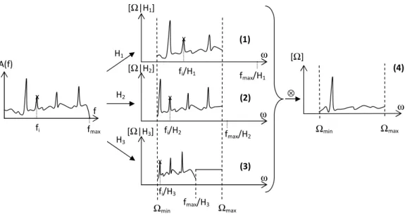
An illustration of the construction of [Ω|Hi] from A(f ) and Hi in the two aforementioned cases is provided in Fig. 4. For orders H1 and H2, fmax/Hi is higher than Ωmax, Eq. (1) can be used (case 1). For order H3, fmax/Hi is lower than Ωmax, Eq. (3) has to be used (case 2: a constant probability is considered between fmax/Hi and Ωmax).
Finally, the probability density functions are multiplied to combine the infor-mation from all considered orders (Fig. 4, Subfig. (4)):
[Ω] ∝ n
Y
i=1
ω ω Ω ω Ω Ω Ω Ω ω Ω Ω Ω ⊗
Fig. 4. Construction of the probability density functions of the rotation frequency, from the instantaneous spectrum and 3 orders of the fundamental rotation
fre-quency. (1),(2): case 1 (fmax/Hi > Ωmax). (3): case 2 (fmax/Hi < Ωmax). (4):
combined pdf.
a formula which reflects the assumption that all random variables Ω|Hi are assumed independent.
3.3 A priori of continuity of the IAS
The method described in the previous section allows the construction of a pdf of the IAS at one specific time step from a short time Fourier transform. In non-stationary conditions, this operation is realized independently for each consecutive time steps and the continuity of the most probable IAS value is thus not guaranteed, although it is an important assumption for any me-chanical system because of the inertia of rotating shafts preventing too strong accelerations/decelerations.
The general concept of introducing an a priori of continuity is depicted in Fig. 5. Let’s note [Ωj] the pdf of the IAS at time step i. The a priori of continuity of the IAS will be enforced as follows:
[Ωj|Ωj+k] = N (Ωj+k, σk) ∝ exp −(ω − Ωj+k) 2 2σ2 k ! (6)
where σk= |γk∆t|, ∆t the time step of the frequency map and γ the standard acceleration of the IAS. A pdf of the rotation frequency at time step j can thus be expressed from the pdf at time j + k:
Ω δ σ σ ω Ω ω Ω ω Ω ω Ω ⊗ ω Ω ω Ω ω Ω Ω σ ω σ ω
Fig. 5. Estimation of the smoothed pdf at time j from pdfs at times j + k (k ∈ [−K...K]) [Ωj]j+k= Z Ωmax Ωmin [Ωj|Ωj+k][Ωj+k]dω ∝ exp −ω 2 2σ2 k ! ∗ [Ωj+k], (7)
where [Ωj]j+k is the pdf of the IAS at time j, obtained by convolving the
pdf [Ωj+k] at time j + k with a centered Gaussian. Several pdfs are thus
available for the IAS at time j, from several time steps j + k before and after j (k ∈ [−K...K]). The variance of the Gaussian law (6) increases with k, which
increases the smoothing effect of the convolution. Note that this formulation
is also correct for k = 0, for which the standard deviation of the Gaussian law is null. In this case, the Gaussian is a Dirac distribution, and Eq. 7 becomes simply [Ωj]j = [Ωj].
Finally, a new version of the pdf of the IAS at time j, including the a priori of continuity, is expressed as follows
[Ωj]s∝ K
Y
k=−K
[Ωj]j+k (8)
where K stands for the considered time interval around j.
4 Application to the wind turbine’s gearbox
The proposed approach is now applied on the vibration signal of the CMMNO’14 contest. The meshing frequencies of the wind turbine gearbox are given in ta-ble 1, with respect to the rotation of the rapid shaft. This tata-ble is deduced from the information provided for the contest, given in Fig. 2. The vibration
Gear pair order 1 / 2 1.025459229 2 / 3 1.025459229 4 / 5 5.316666667 6 / 7 29 8 / 9 15.225 10 / 11 6.619565217 Table 1
Meshing frequencies of the gearbox.
signal was recorded for about 10 minutes, at a sampling rate of 5kHz. A time-frequency map of the signal is given in Fig. 6 (left). The parameters chosen for this spectrogram are
• T = 500ms short time window length,
• zero padding 300% of the short time window length (to achieve a good frequency resolution),
• overlap: 50% of the short time window length,
• uniform weighting window (to ensure a minimum blurring of harmonic com-ponents).
Firstly, the time-frequency map is whitened, in order to remove the response of the structure. The strong fluctuations of the IAS are used here to separate the harmonics from the wideband noise. For each frequency line of the spec-trogram, it is considered that the less energetic time steps are not excited by harmonics. An estimation of the wideband noise is thus obtained by averaging at each frequency the less energetic time steps, the number of which being a priori defined as a fixed proportion of the total time steps.This operation can be written as follows :
A(f, t) = S(f, t)
W (f ) with W (f ) = hS(f, t) × {S(f, t) < Sn(f )}it (9)
where S(f, t) and A(f, t) are the initial and whitened spectrograms, hit stands
for an averaging operator over t, {C} returns 1 (resp. 0) if the condition C is
true (resp. false), and Sn(f ) represents the value exceeded by S(f, t) during
n% of the time at the frequency f (this notation is equivalent to the n-Percent Exceeded Level in environmental acoustics). For the present case of the wind turbine, n is chosen equal to 75%, yet it is noteworthy that this parameter is not very sensitive, and similar results are obtained by setting it between 50
and 90%. This averaging operation over the less energetic time steps (defined
at each frequency) gives an estimation of the average wideband spectrum, and the whole time-frequency map is multiplied at each time step by the inverse of this spectrum. It can be seen in Fig. 6 (right) that the wideband compo-nent of the time-frequency map is efficiently flattened and it can be therefore
assumed that the effect of the structure has been strongly attenuated. An interest of this particular whitening approach, which is efficient only in case of non-stationarity of the rotation speed, is that fixed frequency components are removed because they contribute at all time steps to the same frequencies. Thus, these components are present in the estimation of the wideband spec-trum and are thus removed by the whitening operation. See for instance, in Fig. 6, the constant harmonics between 1200 and 1400 Hz in the original map (left) that are no more visible in the whitened map (right).
Once the whitening step is completed, each column of the spectrogram is
time (s) frequency (Hz) 100 200 300 400 500 0 200 400 600 800 1000 1200 1400 1600 1800 dB −65 −60 −55 −50 −45 −40 −35 −30 −25 −20 time (s) frequency (Hz) 100 200 300 400 500 0 200 400 600 800 1000 1200 1400 1600 1800 dB −50 −45 −40 −35 −30 −25 −20 −15 −10 −5 0
Fig. 6. Time-frequency map of the vibration signal before (left) / after (right) whitening.
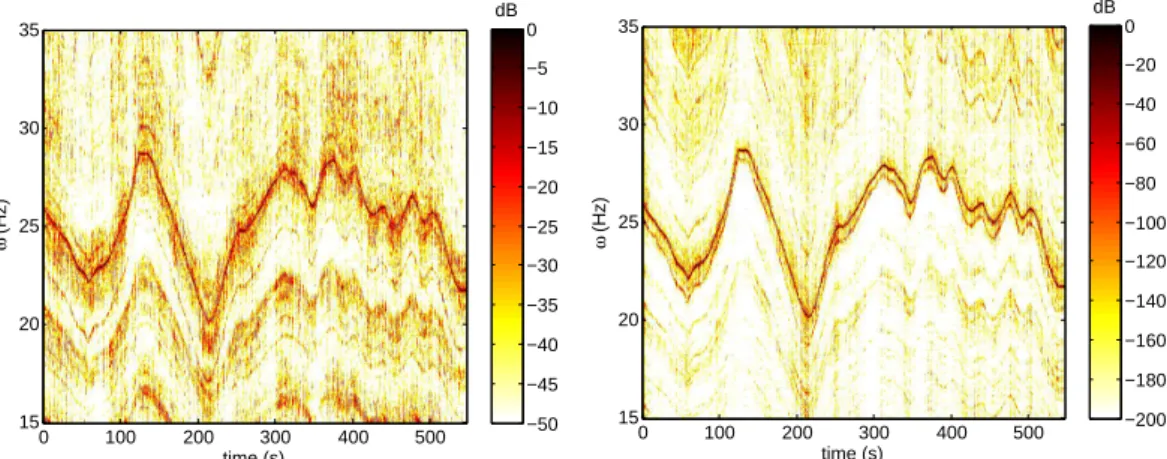
used as one instantaneous spectrum to build a pdf of the IAS at each time step, as described in section 3.2. These pdfs will be presented in the following as pdf maps. The pdf map obtained using the 6 fundamental meshing orders given in table 1 is displayed in Fig. 7 (left). The time evolution of the IAS is visible in this figure, but the map is not really clean due to a lot of secondary local maxima still visible outside the main frequency trace. The 10 first har-monics of all fundamental meshing orders are then considered, that is to say a total of 60 orders, to obtain the pdf map given in Fig. 7 (right). The map is much clearer, and the dynamic much wider, which illustrates the interest to take into account as many orders as possible in the approach. This could be received as a satisfying result, but at this stage the a priori of continuity of the rotation frequency has still not been taken into account. In other words, the pdfs obtained at each time step are obtained from the short time Fourier transform: one column of the spectrogram is used to build one column of the pdf map.
The last step of the probabilist approach, described in section 3.3, is to enforce an a priori of continuity to the IAS. At this stage, all pdfs in a given time inter-val around the considered time step are combined to obtained a ”smoothed” one, embedding the a priori of continuity. The key parameter for this oper-ation is the standard devioper-ation of the Gaussian law (Eq. (6)), depending on the a priori tolerance γ on the acceleration. In this work, γ is choosen equal to 0.2Hz/s. This choice can be made by inspecting the previously obtained
time (s) ω (Hz) 0 100 200 300 400 500 15 20 25 30 35 dB −50 −45 −40 −35 −30 −25 −20 −15 −10 −5 0 time (s) ω (Hz) 0 100 200 300 400 500 15 20 25 30 35 dB −200 −180 −160 −140 −120 −100 −80 −60 −40 −20 0
Fig. 7. Pdf of the IAS at each time step, considering fundamental meshing orders (left) and considering fundamental meshing orders and their 10 first harmonics (right).
pdf map, and roughly estimating the rate of change in the IAS. However, it is noteworthy that this parameter is not too sensitive and equivalent results are obtained in a range from 0.1 to 0.4Hz/s.The parameter K in Eq. (8) is chosen
so as to take into account, for the estimation of the smoothed pdf at time t0,
the pdfs in the time window [t0± 10s]. Considering that the time resolution of
the spectrogram is 250ms, K is equal to 40. The pdf map resulting from this
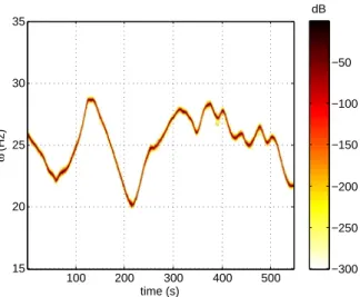
operation is drawn in Fig. 8. It is significantly cleaned and the resulting pdfs are characterized by clear and well defined maximum values. The expected values of pdfs are extracted, at each time step, to obtain the evolution as a function of the time (Fig. 9, left). This result is compared, in the same figure, with the IAS directly measured with the angle encoder (the reference of the CMMNO’14 contest). The estimation error is also calculated (Fig. 9, right), and it can be seen that this error, most often comprised between ±0.1% never exceeds ±0.4%.
Conclusion
The organization of a contest, during an international conference, on a spe-cific application case, is a very interesting and original way of establishing the state-of-the-art in a particular domain. It gives an objective picture of what people actually use to solve one given problem. The short delay left to contes-tants to bring a solution is also a key point, because it requires them to use their existing techniques and algorithms, with limited possibilities to develop other specific approaches. It thus allows to assess the robustness and generality of up-to-date techniques. In the present case, the debriefing of contributions led to a valuable analysis, emphasizing a common weakness of existing methods: the fact that the IAS is generally tracked using only one harmonic component. The method proposed in this work has been conceived from this observation, and the problem of estimating the IAS has been reconsidered in the frame of
time (s) ω (Hz) 100 200 300 400 500 15 20 25 30 35 dB −300 −250 −200 −150 −100 −50
Fig. 8. Pdf of the IAS at each time step, considering fundamental meshing orders and their 10 first harmonics, with smoothing.
100 200 300 400 500 20 21 22 23 24 25 26 27 28 29 time (s) Ω (Hz) 50 100 150 200 250 300 350 400 450 500 −0.5 −0.4 −0.3 −0.2 −0.1 0 0.1 0.2 0.3 0.4 0.5 time (s) Error (%)
Fig. 9. Left: measured (solid black) and identified (dotted red) IAS. Right: relative error with respect to the reference (%).
a probabilistic formalism, trying to take advantage of any available a priori information on the studied mechanism. This approach has been evaluated in the frame of the contest case and showed a significant improvement of results as compared to the contest contributions.
Acknowledgements
The authors want to acknowledge the CMMNO 2014 Organization Com-mittee for its help and support. All contestants are also warmly acknowledged for their contributions. The company OROS is acknowledged for providing the first prize award. This work was performed within the framework of the Labex CeLyA of Universit´e de Lyon, operated by the French National Re-search Agency (ANR-10-LABX-0060/ ANR-11-IDEX-0007).
References
[1] D. R´emond, J. Antoni, and R.B. Randall. Editorial for the special issue
on instantaneous angular speed (ias) processing and angular applications.
Mechanical Systems and Signal Processing, 44(1-2):1 – 4, 2014. Special Issue
on Instantaneous Angular Speed (IAS) Processing and Angular Applications. [2] D. R´emond, J. Antoni, and R.B. Randall. Instantaneous angular speed (ias)
processing and related angular applications. Mechanical Systems and Signal
Processing, 45(1):24 – 27, 2014.
[3] Jing Lin and Ming Zhao. A review and strategy for the diagnosis of speed-varying machinery. In Prognostics and Health Management (PHM), 2014 IEEE
Conference on, pages 1–9, June 2014.
[4] Anders Brandt, Thomas Lago, Kjell Ahlin, and Jiri Tuma. Main principles and limitations of current order tracking methods. Sound and Vibration, 39(3):19– 22, 2005.
[5] K.S. Wang and P.S. Heyns. The combined use of order tracking techniques for enhanced fourier analysis of order components. Mechanical Systems and Signal
Processing, 25(3):803 – 811, 2011.
[6] K.S. Wang, D. Guo, and P.S. Heyns. The application of order tracking for vibration analysis of a varying speed rotor with a propagating transverse crack.
Engineering Failure Analysis, 21:91 – 101, 2012.
[7] P. Borghesani, P. Pennacchi, S. Chatterton, and R. Ricci. The velocity
synchronous discrete fourier transform for order tracking in the field of rotating machinery. Mechanical Systems and Signal Processing, 44(1-2):118 – 133, 2014. Special Issue on Instantaneous Angular Speed (IAS) Processing and Angular Applications.
[8] H. Vold and J. Leuridan. High resolution order tracking at extreme slew rates, using kalman tracking filters. Society of Automotive Engineers, SAE paper No 931288, 1993.
[9] H. Vold, M. Mains, and J. Blough. Theoretical foundations for high performance order tracking with the vold-kalman tracking filter. Society of Automotive
Engineers, SAE Paper 972007, 1997.
[10] C. Feldbauer and R. Holdrich. Realization of a vold-kalman tracking filter - a least squares problem. In Proceedings of the COST G-6 Conference on Digital
Audio Effects, Verona, Italy, 2000.
[11] Mingsian Bai, Jiamin Huang, Minghong Hong, and Fucheng Su. Fault diagnosis of rotating machinery using an intelligent order tracking system. Journal of
Sound and Vibration, 280(3-5):699 – 718, 2005.
[12] M.-Ch. Pan and Y.-F. Lin. Further exploration of vold-kalman-filtering
order tracking with shaft-speed information-i: Theoretical part, numerical implementation and parameter investigations. Mechanical Systems and Signal
[13] Min-Chun Pan and Cheng-Xue Wu. Adaptive vold-kalman filtering order tracking. Mechanical Systems and Signal Processing, 21(8):2957 – 2969, 2007. [14] F. Bonnardot, M. El Badaoui, R.B. Randall, J. Dani`ere, and F. Guillet. Use
of the acceleration signal of a gearbox in order to perform angular resampling (with limited speed fluctuation). Mechanical Systems and Signal Processing, 19(4):766 – 785, 2005.
[15] Jacek Urbanek, Tomasz Barszcz, and Jerome Antoni. Time-frequency approach to extraction of selected second-order cyclostationary vibration components for varying operational conditions. Measurement, 46(4):1454 – 1463, 2013.
[16] P. Borghesani, R. Ricci, S. Chatterton, and P. Pennacchi. A new procedure for using envelope analysis for rolling element bearing diagnostics in variable operating conditions. Mechanical Systems and Signal Processing, 38(1):23 – 35, 2013. Condition monitoring of machines in non-stationary operations.
[17] Weidong Cheng, Robert X. Gao, Jinjiang Wang, Tianyang Wang, Weigang Wen, and Jianyong Li. Envelope deformation in computed order tracking and error in order analysis. Mechanical Systems and Signal Processing, 48(1-2):92 – 102, 2014.
[18] J. Antoni, J. Daniere, and F. Guillet. Effective vibration analysis of ic engines using cyclostationarity. part i-a methodology for condition monitoring. Journal
of Sound and Vibration, 257(5):815 – 837, 2002.
[19] Luisa F. Villa, Anibal Renones, Jose R. Peran, and Luis J. de Miguel. Angular resampling for vibration analysis in wind turbines under non-linear speed fluctuation. Mechanical Systems and Signal Processing, 25(6):2157 – 2168, 2011. Interdisciplinary Aspects of Vehicle Dynamics.
[20] Marco Cocconcelli, Luca Bassi, Cristian Secchi, Cesare Fantuzzi, and Riccardo Rubini. An algorithm to diagnose ball bearing faults in servomotors running arbitrary motion profiles. Mechanical Systems and Signal Processing, 27:667 – 682, 2012.
[21] J. Antoni, F. Bonnardot, A. Raad, and M. El Badaoui. Cyclostationary
modelling of rotating machine vibration signals. Mechanical Systems and Signal
Processing, 18(6):1285 – 1314, 2004.
[22] J. Antoni. Cyclostationarity by examples. Mechanical Systems and Signal
Processing, 23(4):987 – 1036, 2009.
[23] Dany Abboud, Jerome Antoni, Mario Eltabach, and Sophie Sieg-Zieba. Angletime cyclostationarity for the analysis of rolling element bearing vibrations. Measurement, 75:29 – 39, 2015.
[24] D. Abboud, J. Antoni, S. Sieg-Zieba, and M. Eltabach. Deterministic-random separation in nonstationary regime. Journal of Sound and Vibration, pages –, 2015.
[25] Ahmed Yousef Ben Sasi, Fengshou Gu, Bradley Payne, and Andrew Ball. Instantaneous angular speed monitoring of electric motors. Journal of Quality
in Maintenance Engineering, 10(2):123–135, 2004.
[26] Jianguo Yang, Lijun Pu, Zhihua Wang, Yichen Zhou, and Xinping Yan. Fault detection in a diesel engine by analysing the instantaneous angular speed.
Mechanical Systems and Signal Processing, 15(3):549 – 564, 2001.
[27] M. Desbazeille, R.B. Randall, F. Guillet, M. El Badaoui, and C. Hoisnard. Model-based diagnosis of large diesel engines based on angular speed variations of the crankshaft. Mechanical Systems and Signal Processing, 24(5):1529 – 1541, 2010. Special Issue: Operational Modal Analysis.
[28] L. Renaudin, F. Bonnardot, O. Musy, J.B. Doray, and D. R´emond. Natural roller bearing fault detection by angular measurement of true instantaneous angular speed. Mechanical Systems and Signal Processing, 24(7):1998 – 2011, 2010. Special Issue: ISMA 2010.
[29] Adeline Bourdon, Hugo Andr´e, and Didier R´emond. Introducing angularly periodic disturbances in dynamic models of rotating systems under non-stationary conditions. Mechanical Systems and Signal Processing, 44(1-2):60 – 71, 2014. Special Issue on Instantaneous Angular Speed (IAS) Processing and Angular Applications.
[30] M. Lamraoui, M. Thomas, M. El Badaoui, and F. Girardin. Indicators
for monitoring chatter in milling based on instantaneous angular speeds.
Mechanical Systems and Signal Processing, 44(1-2):72 – 85, 2014. Special Issue
on Instantaneous Angular Speed (IAS) Processing and Angular Applications. [31] R. Potter. A new order tracking method for rotating machinery. Sound and
Vibration, 7:30–34, 1990.
[32] K.R. Fyfe and E.D.S. Munck. Analysis of computed order tracking. Mechanical
Systems and Signal Processing, 11(2):187 – 205, 1997.
[33] K.m. Bossley, R.j. Mckendrick, C.j. Harris, and C. Mercer. Hybrid computed order tracking. Mechanical Systems and Signal Processing, 13(4):627 – 641, 1999.
[34] Yuhua Li, Fengshou Gu, Georgina Harris, Andrew Ball, Nick Bennett, and Ken Travis. The measurement of instantaneous angular speed. Mechanical Systems
and Signal Processing, 19(4):786 – 805, 2005.
[35] P.N. Saavedra and C.G. Rodriguez. Accurate assessment of computed order tracking. Shock and Vibration, 13:13–32, 2006.
[36] Fengshou Gu, Isa Yesilyurt, Yuhua Li, Georgina Harris, and Andrew Ball. An investigation of the effects of measurement noise in the use of instantaneous angular speed for machine diagnosis. Mechanical Systems and Signal Processing, 20(6):1444 – 1460, 2006. Special Issue: Laser Doppler Vibrometry.
[37] S.D. Yu and X. Zhang. A data processing method for determining instantaneous angular speed and acceleration of crankshaft in an aircraft engine-propeller system using a magnetic encoder. Mechanical Systems and Signal Processing, 24(4):1032 – 1048, 2010.
[38] K. Janssens, P. Van Vlierberghe, W. Claes, B. Peeters, T. Martens, and Ph. D’Hondt. Zebra tape butt joint detection and correction algorithm for rotating shafts with torsional vibrations. In Proceedings of the ISMA 2010,
International Conference on Modal Analysis Noise and Vibration Engineering,
Leuven, Belgium, 2010.
[39] M. El Badaoui and F. Bonnardot. Impact of the non-uniform angular sampling on mechanical signals. Mechanical Systems and Signal Processing, 44(1-2):199 – 210, 2014. Special Issue on Instantaneous Angular Speed (IAS) Processing and Angular Applications.
[40] Alessandro Rivola and Marco Troncossi. Zebra tape identification for the
instantaneous angular speed computation and angular resampling of motorbike valve train measurements. Mechanical Systems and Signal Processing, 44(1-2):5 – 13, 2014. Special Issue on Instantaneous Angular Speed (IAS) Processing and Angular Applications.
[41] H. Andr´e, F. Girardin, A. Bourdon, J. Antoni, and D. R´emond. Precision of the {IAS} monitoring system based on the elapsed time method in the spectral domain. Mechanical Systems and Signal Processing, 44(1-2):14 – 30, 2014. Special Issue on Instantaneous Angular Speed (IAS) Processing and Angular Applications.
[42] Q. Lecl`ere, F. Girardin, and D. R´emond. An analysis of instantaneous angular speed measurement errors. In Proceedings of Surveillance 7, Chartres, France, 2013.
[43] F. Combet and L. Gelman. An automated methodology for performing time synchronous averaging of a gearbox signal without speed sensor. Mechanical
Systems and Signal Processing, 21(6):2590 – 2606, 2007.
[44] R. Zimroz, J. Urbanek, T. Barszcz, W. Bartelmus, F. Millioz, and N. Martin. Measurement of instantaneous shaft speed by advanced vibration signal processing-application to wind turbine gearbox. Metrology and Measurement
Systems, 13:701–712, 2011.
[45] Ming Zhao, Jing Lin, Xiufeng Wang, Yaguo Lei, and Junyi Cao. A tacho-less order tracking technique for large speed variations. Mechanical Systems and
Signal Processing, 40(1):76 – 90, 2013.
[46] Michael D. Coats and Robert B. Randall. Single and multi-stage phase
demodulation based order-tracking. Mechanical Systems and Signal Processing, 44(1-2):86 – 117, 2014. Special Issue on Instantaneous Angular Speed (IAS) Processing and Angular Applications.
[47] Jean-Luc Dion, Cyrille Stephan, Gael Chevallier, and Hugo Festjens. Tracking and removing modulated sinusoidal components: A solution based on the
kurtosis and the extended kalman filter. Mechanical Systems and Signal Processing, 38(2):428 – 439, 2013.
[48] Konstantinos Rodopoulos, Christos Yiakopoulos, and Ioannis Antoniadis. A parametric approach for the estimation of the instantaneous speed of rotating machinery. Mechanical Systems and Signal Processing, 44(1-2):31 – 46, 2014. Special Issue on Instantaneous Angular Speed (IAS) Processing and Angular Applications.
[49] O. Cardona-Morales, L.D. Avendano, and G. Castellanos-Dominguez. Nonlinear model for condition monitoring of non-stationary vibration signals in ship driveline application. Mechanical Systems and Signal Processing, 44(1-2):134 – 148, 2014. Special Issue on Instantaneous Angular Speed (IAS) Processing and Angular Applications.
[50] Konstantinos C. Gryllias and Ioannis A. Antoniadis. Estimation of the
instantaneous rotation speed using complex shifted morlet wavelets. Mechanical
Systems and Signal Processing, 38(1):78 – 95, 2013. Condition monitoring of
machines in non-stationary operations.
[51] Hui Shao, Wei Jin, and S. Qian. Order tracking by discrete gabor expansion.
Instrumentation and Measurement, IEEE Transactions on, 52(3):754–761, June
2003.
[52] Junsheng Cheng, Yu Yang, and Dejie Yu. Application of the improved
generalized demodulation time-frequency analysis method to multi-component signal decomposition. Signal Processing, 89(6):1205 – 1215, 2009.
[53] Zhipeng Feng, Fulei Chu, and Ming J. Zuo. Time-frequency analysis of time-varying modulated signals based on improved energy separation by iterative generalized demodulation. Journal of Sound and Vibration, 330(6):1225 – 1243, 2011.
[54] Krzysztof Czarnecki. The instantaneous frequency rate spectrogram.
Mechanical Systems and Signal Processing, 66-67:361 – 373, 2016.
[55] Ioannis A. Antoniadis, Christos T. Yiakopoulos, Konstantinos C. Gryllias, and Konstantinos I. Rodopoulos. Ifesis: Instantaneous frequencies estimation via subspace invariance properties of wavelet structures. Mechanical Systems and
Signal Processing, 49(1-2):264 – 284, 2014.
[56] B. Boashash, P. O’Shea, and M. Arnold. Algorithms for instantaneous frequency estimation: a comparative study. In Proceedings SPIE Conference Advanced
Algorithms Architectures Signal Process. V, San Diego, CA, USA, 1990.
[57] B. Boashash. Estimating and interpreting the instantaneous frequency of a signal. i. fundamentals. Proceedings of the IEEE, 80(4):520–538, Apr 1992. [58] B. Boashash. Estimating and interpreting the instantaneous frequency of a
signal. ii. algorithms and applications. Proceedings of the IEEE, 80(4):540–568, Apr 1992.
[59] Arthur E. Barnes. The calculation of instantaneous frequency and instantaneous bandwidth. Geophysics, 57(11):1520–1524, 1992.
[60] S. Sheng. Report on wind turbine subsystem reliability - a survey of various databases. Technical report, National Renewable Energy Laboratory (NREL), 2013.
![Fig. 1. Wind stat data base, 2008-2012 aggregated downtime per turbine system[60].](https://thumb-eu.123doks.com/thumbv2/123doknet/14376836.505244/7.892.202.671.112.484/fig-wind-stat-data-aggregated-downtime-turbine-system.webp)

![Fig. 5. Estimation of the smoothed pdf at time j from pdfs at times j + k (k ∈ [−K...K]) [Ω j ] j+k = Z Ω max Ω min [Ω j |Ω j+k ][Ω j+k ]dω ∝ exp −ω 2 2σ 2 k ! ∗ [Ω j + k ], (7)](https://thumb-eu.123doks.com/thumbv2/123doknet/14376836.505244/13.892.196.677.115.401/fig-estimation-smoothed-time-pdfs-times-ω-ω.webp)