i
Publications in International Conferences as Poster:
1. E.F. MOHAMED , C. ANDRIANTSIFERANA , H. DELMAS, A. M. WILHELM.
Élimination des Composés Phénoliques par Charbons Actifs Issus de Boues. Xèmes Journées Cathala-Letort de prospective scientifique et technique, SFGP,Octobre 2008 "Le Génie des Procédés au service de l’Environnement - Enjeux et défis.
2. E.F. MOHAMED, C. ANDRIANTSIFERANA, H. DELMAS, A. M. WILHELM.
Competitive Adsorption of Phenolic Compounds from Aqueous Solution using Sludge Based Activated Carbon. the International Green Process Engineering Congress and the European Process Intensification Conference, 14-17 june 2009 ,Venice, Italy.
3. E.F. MOHAMED, C. ANDRIANTSIFERANA, H. DELMAS, A. M. WILHELM.
Photocatalytic Regeneration of Activated Carbon Saturated with Phenol using Novel Kind of Combined TiO2-AC Tissue. International Journée Européenne de la
photocatalyse, JEP), 21 et 22 Septembre 2009, Cité Mondiale , Bordeaux (France).
4. E.F. Mohamed, C. Andriantsiferana, H. Delmas. Influence of Temperature, pH and
Inorganic Salt on the Removal of Phenols from Aqueous solution and Industrial Effluent onto Commercial Activated Carbon S23. International IWA: « Sustainable Solution for Small Water and Wastewater Treatment Systems (S2Small 2010) 19-22 April 2010, Girona, Catalonia (Spain).
Publications in International Conferences as Oral Presentation:
1. E.F. MOHAMED, C. ANDRIANTSIFERANA, H. DELMAS. Towards a New
Sustainable Sequential Process for Wastewater Treatment using Sludge Based Activated Carbon. 3rd International Conference of Environmental Research Division,
ii April 1-3, 2008.
2. E.F. MOHAMED, C. ANDRIANTSIFERANA, H. DELMAS. Photocatalytic
oxidation of phenol under UV irradiation on a combined TiO2-AC Tissue.
International “Ozone and UV: Leading-edge science and technologies” 23-27 May 2011, Paris, France.
Scientific papers :
1. C. J. LEBIGUE, C. ANDRIANTSIFERANA, N. KROU , C. AYRAL , E.F.
MOHAMED, A.M. WILHELM ,H. DELMAS , L. LE COQ , C. GERENTE ,K. M.
SMITH , S. PULLKET , G FOWLER , N.J.D. GRAHAM (2010). Application of sludge-based carbonaceous materials in a hybrid water treatment process based on adsorption and catalytic wet air oxidation. Journal of Environmental Management .91: 2432 – 2439.
2. E.F. MOHAMED, C. ANDRIANTSIFERANA, A.M. WILHELM , H. DELMAS (2011).
Competitive adsorption of phenolic compounds from aqueous solution using sludge based activated carbon. Environmental Technology. Pages 1–12.
iii
This thesis is the result of many a long hour involving arduous research and the culmination
This thesis is the result of many a long hour involving arduous research and the culmination
This thesis is the result of many a long hour involving arduous research and the culmination
This thesis is the result of many a long hour involving arduous research and the culmination
of a process that included the constant assistance, support & guidance afforded to me by my
of a process that included the constant assistance, support & guidance afforded to me by my
of a process that included the constant assistance, support & guidance afforded to me by my
of a process that included the constant assistance, support & guidance afforded to me by my
professors
professors
professors
professors whom I
whom I
whom I
whom I am deeply indebted. This achievement been accomplished, in no small
am deeply indebted. This achievement been accomplished, in no small
am deeply indebted. This achievement been accomplished, in no small
am deeply indebted. This achievement been accomplished, in no small
measure, due to their sheer professionalism and dedication which they demonstrated time
measure, due to their sheer professionalism and dedication which they demonstrated time
measure, due to their sheer professionalism and dedication which they demonstrated time
measure, due to their sheer professionalism and dedication which they demonstrated time
after time. It is to them that I owe my heartfelt thanks and the overwhelming sense of
after time. It is to them that I owe my heartfelt thanks and the overwhelming sense of
after time. It is to them that I owe my heartfelt thanks and the overwhelming sense of
after time. It is to them that I owe my heartfelt thanks and the overwhelming sense of
satisfaction
satisfaction
satisfaction
satisfaction that I feel at this stage.
that I feel at this stage.
that I feel at this stage.
that I feel at this stage.
First of all, I would like to express my deepest appreciation to my supervisor, Prof. Henri
First of all, I would like to express my deepest appreciation to my supervisor, Prof. Henri
First of all, I would like to express my deepest appreciation to my supervisor, Prof. Henri
First of all, I would like to express my deepest appreciation to my supervisor, Prof. Henri
DELMAS, for his guidance, encouragement, tremendous support and advice throughout my
DELMAS, for his guidance, encouragement, tremendous support and advice throughout my
DELMAS, for his guidance, encouragement, tremendous support and advice throughout my
DELMAS, for his guidance, encouragement, tremendous support and advice throughout my
work. His effort, time and patience in proofreadin
work. His effort, time and patience in proofreadin
work. His effort, time and patience in proofreadin
work. His effort, time and patience in proofreading and giving useful comments and
g and giving useful comments and
g and giving useful comments and
g and giving useful comments and
suggestions on my manuscript and research presentations were invaluable. He has also
suggestions on my manuscript and research presentations were invaluable. He has also
suggestions on my manuscript and research presentations were invaluable. He has also
suggestions on my manuscript and research presentations were invaluable. He has also
encouraged and challenged me in ways that enhanced my professional growth.
encouraged and challenged me in ways that enhanced my professional growth.
encouraged and challenged me in ways that enhanced my professional growth.
encouraged and challenged me in ways that enhanced my professional growth.
Special thanks to Dr. Caroline ANDERIANSEFERANA, co
Special thanks to Dr. Caroline ANDERIANSEFERANA, co
Special thanks to Dr. Caroline ANDERIANSEFERANA, co
Special thanks to Dr. Caroline ANDERIANSEFERANA, co----director o
director o
director o
director of thesis,
f thesis,
f thesis,
f thesis, who
who
who
who
greatly enriched my knowledge & constantly inspired me and who, in my pursuit of this
greatly enriched my knowledge & constantly inspired me and who, in my pursuit of this
greatly enriched my knowledge & constantly inspired me and who, in my pursuit of this
greatly enriched my knowledge & constantly inspired me and who, in my pursuit of this
thesis, had to sacrifice many of her precious hours. She has been able to skilfully manage this
thesis, had to sacrifice many of her precious hours. She has been able to skilfully manage this
thesis, had to sacrifice many of her precious hours. She has been able to skilfully manage this
thesis, had to sacrifice many of her precious hours. She has been able to skilfully manage this
research without forgetting the ever essential human relatio
research without forgetting the ever essential human relatio
research without forgetting the ever essential human relatio
research without forgetting the ever essential human relationships. From deep inside thank
nships. From deep inside thank
nships. From deep inside thank
nships. From deep inside thank
you and your family for their opportune support and help.
you and your family for their opportune support and help.
you and your family for their opportune support and help.
you and your family for their opportune support and help.
I would like to acknowledge Prof. Iordan NIKOV and Prof. Stephan BROSILLION for
I would like to acknowledge Prof. Iordan NIKOV and Prof. Stephan BROSILLION for
I would like to acknowledge Prof. Iordan NIKOV and Prof. Stephan BROSILLION for
I would like to acknowledge Prof. Iordan NIKOV and Prof. Stephan BROSILLION for
accepting to be the Reporters of my thesis and. Prof. Marie Hélène MANERO,
accepting to be the Reporters of my thesis and. Prof. Marie Hélène MANERO,
accepting to be the Reporters of my thesis and. Prof. Marie Hélène MANERO,
accepting to be the Reporters of my thesis and. Prof. Marie Hélène MANERO, Dr.
Dr.
Dr.
Dr.
Florence BENOIT
Florence BENOIT
Florence BENOIT
Florence BENOIT----MARQUIE , Dr. Sabine SOCHARD and Dr. Cedric VALLET to be
MARQUIE , Dr. Sabine SOCHARD and Dr. Cedric VALLET to be
MARQUIE , Dr. Sabine SOCHARD and Dr. Cedric VALLET to be
MARQUIE , Dr. Sabine SOCHARD and Dr. Cedric VALLET to be
a part of the jury member. I’m grateful for their valuable suggestions on the thesis work.
a part of the jury member. I’m grateful for their valuable suggestions on the thesis work.
a part of the jury member. I’m grateful for their valuable suggestions on the thesis work.
a part of the jury member. I’m grateful for their valuable suggestions on the thesis work.
I also would like to express my gratitude towards all the staff
I also would like to express my gratitude towards all the staff
I also would like to express my gratitude towards all the staff
I also would like to express my gratitude towards all the staff members of LGC for
members of LGC for
members of LGC for
members of LGC for
their invaluable help. Special thanks to Jean
their invaluable help. Special thanks to Jean
their invaluable help. Special thanks to Jean
their invaluable help. Special thanks to Jean----Louis NADALIN, Lahcen FARHI, Alec
Louis NADALIN, Lahcen FARHI, Alec
Louis NADALIN, Lahcen FARHI, Alec
Louis NADALIN, Lahcen FARHI, Alec
MAUNOURY, Christine REY ROUCH, Marie
MAUNOURY, Christine REY ROUCH, Marie
MAUNOURY, Christine REY ROUCH, Marie
MAUNOURY, Christine REY ROUCH, Marie----Line PERN and Lucien POLLINI for
Line PERN and Lucien POLLINI for
Line PERN and Lucien POLLINI for
Line PERN and Lucien POLLINI for
their great help.
their great help.
their great help.
their great help.
iv
friendship over the past four years. my special thanks to
friendship over the past four years. my special thanks to
friendship over the past four years. my special thanks to
friendship over the past four years. my special thanks to my colleagues and friends, Harold ,
my colleagues and friends, Harold ,
my colleagues and friends, Harold ,
my colleagues and friends, Harold ,
Cinthia, Mary, Isa , Cathy, Benjamin, Nicola ,
Cinthia, Mary, Isa , Cathy, Benjamin, Nicola ,
Cinthia, Mary, Isa , Cathy, Benjamin, Nicola ,
Cinthia, Mary, Isa , Cathy, Benjamin, Nicola , Marianne,
Marianne,
Marianne, Raluca, Ali,
Marianne,
Raluca, Ali,
Raluca, Ali, Joaquim
Raluca, Ali,
Joaquim
Joaquim and
Joaquim
and
and Rana
and
Rana
Rana
Rana
for their moral supports during the completion of this r
for their moral supports during the completion of this r
for their moral supports during the completion of this r
for their moral supports during the completion of this research work and who have
esearch work and who have
esearch work and who have
esearch work and who have
contributed to make my stay very pleasant.
contributed to make my stay very pleasant.
contributed to make my stay very pleasant.
contributed to make my stay very pleasant.
I am the most grateful to my husband
I am the most grateful to my husband
I am the most grateful to my husband
I am the most grateful to my husband Gamal AWAD who
Gamal AWAD who
Gamal AWAD who overflows me with love and
Gamal AWAD who
overflows me with love and
overflows me with love and
overflows me with love and
inspiration day by day; I share this accomplishment with you. Thank you for your
inspiration day by day; I share this accomplishment with you. Thank you for your
inspiration day by day; I share this accomplishment with you. Thank you for your
inspiration day by day; I share this accomplishment with you. Thank you for your
encouragement, for believi
encouragement, for believi
encouragement, for believi
encouragement, for believing in my capabilities, moral supports in all the good and hard
ng in my capabilities, moral supports in all the good and hard
ng in my capabilities, moral supports in all the good and hard
ng in my capabilities, moral supports in all the good and hard
times and patience in the last years. I would like to thank my children (Amr and Reem) from
times and patience in the last years. I would like to thank my children (Amr and Reem) from
times and patience in the last years. I would like to thank my children (Amr and Reem) from
times and patience in the last years. I would like to thank my children (Amr and Reem) from
the bottom of my heart for their love.
the bottom of my heart for their love.
the bottom of my heart for their love.
the bottom of my heart for their love.
To Zinab and Farouk, my beloved parents, I dedicate this work
To Zinab and Farouk, my beloved parents, I dedicate this work
To Zinab and Farouk, my beloved parents, I dedicate this work
To Zinab and Farouk, my beloved parents, I dedicate this work in their loving memory and
in their loving memory and
in their loving memory and
in their loving memory and
honour. Daddy, although you are not here in flesh anymore, you continuously inspire me in
honour. Daddy, although you are not here in flesh anymore, you continuously inspire me in
honour. Daddy, although you are not here in flesh anymore, you continuously inspire me in
honour. Daddy, although you are not here in flesh anymore, you continuously inspire me in
everything I do. You honed me into the person that I am right now. Mom, thank you so
everything I do. You honed me into the person that I am right now. Mom, thank you so
everything I do. You honed me into the person that I am right now. Mom, thank you so
everything I do. You honed me into the person that I am right now. Mom, thank you so
much for being my first teacher. Dad, thank you for t
much for being my first teacher. Dad, thank you for t
much for being my first teacher. Dad, thank you for t
much for being my first teacher. Dad, thank you for teaching me how to be a strong person
eaching me how to be a strong person
eaching me how to be a strong person
eaching me how to be a strong person
unconsciously by making me get back up whenever I stumble. Daddy and Mommy, thank
unconsciously by making me get back up whenever I stumble. Daddy and Mommy, thank
unconsciously by making me get back up whenever I stumble. Daddy and Mommy, thank
unconsciously by making me get back up whenever I stumble. Daddy and Mommy, thank
you for being the best parents I ever had, for the unconditional love that you gave me, and
you for being the best parents I ever had, for the unconditional love that you gave me, and
you for being the best parents I ever had, for the unconditional love that you gave me, and
you for being the best parents I ever had, for the unconditional love that you gave me, and
for instilling me the confidence that I am ca
for instilling me the confidence that I am ca
for instilling me the confidence that I am ca
for instilling me the confidence that I am capable of doing anything I put my mind to.
pable of doing anything I put my mind to.
pable of doing anything I put my mind to.
pable of doing anything I put my mind to.
Special thanks to all my family members especially my sweet sister Eman , my brothers
Special thanks to all my family members especially my sweet sister Eman , my brothers
Special thanks to all my family members especially my sweet sister Eman , my brothers
Special thanks to all my family members especially my sweet sister Eman , my brothers
Ahmed and Ehab , for their continuous faith and support. I would like to thank my country
Ahmed and Ehab , for their continuous faith and support. I would like to thank my country
Ahmed and Ehab , for their continuous faith and support. I would like to thank my country
Ahmed and Ehab , for their continuous faith and support. I would like to thank my country
Egypt for funding my research for fo
Egypt for funding my research for fo
Egypt for funding my research for fo
Egypt for funding my research for four years.
ur years.
ur years.
ur years.
Finally, always thank God for giving me so much blessings, and
Finally, always thank God for giving me so much blessings, and
Finally, always thank God for giving me so much blessings, and
Finally, always thank God for giving me so much blessings, and I ask that I will be able to
I ask that I will be able to
I ask that I will be able to
I ask that I will be able to
use such gifts to help those in need.
use such gifts to help those in need.
use such gifts to help those in need.
use such gifts to help those in need.
v In order to explore a new sequential process for water treatment its two steps, adsorption on activated carbon and in situ photocatalytic oxidative regeneration, were investigated successively.
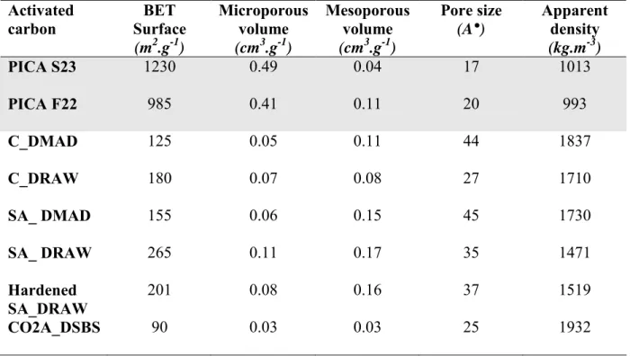
Several commercial activated carbons (AC) and sewage sludge based activated carbons (SBAC) were tested with several phenols and one dye as pollutants. Despite low BET surface SBAC exhibits convenient adsorption properties.
Photocatalysis on TiO2 was carried out with several materials to achieve activated
carbon adsorption-regeneration process: a multilayer tissue with fixed granular AC and TiO2
on a sheet, a composite with TiO2, CVD deposited on AC, and AC-TiO2 powder mixture for
comparison. Promising results were obtained especially with TiO2 deposited on AC proving
the vicinity of adsorption and photocatalytic sites to be beneficial.
Keywords: water treatment; sludge; activated carbons; multicomponent adsorption; phenols;
vi Les effluents industriels sont constitués de molécules de natures très diverses, plus ou moins réfractaires aux classiques traitements biologiques. Les normes de rejets évoluant régulièrement vers des contraintes de plus en plus sévères, il semble aujourd’hui nécessaire de proposer des solutions complémentaires pour atteindre de hauts rendements d’épuration. Le premier procédé mis en œuvre dans ce travail est l’adsorption sur charbon actif. Le caractère novateur de cette technique se situe dans l’utilisation de charbons actifs fabriqués à partir de boues de stations d’épuration d’eaux usées. La seconde méthode est un procédé hybride innovant combinant adsorption et photocatalyse avec TiO2. Les eaux industrielles ciblées sont
les effluents colorés, représentés par la tartrazine, et les effluents phénolés représentés par le phénol, l’acide p-hydroxybenzoïque, le p-chlorophénol er le p-nitrophénol. Pour traiter par adsorption les eaux chargées en phénols, plusieurs charbons actifs commerciaux et six charbons de boues ont été utilisés. Il ressort de cette première étude que, malgré leurs faibles surfaces spécifiques, certains charbons de boues présentent des performances très satisfaisantes. Le procédé séquentiel combinant adsorption et photocatalyse a été réalisé avec plusieurs matériaux: un tissu Ahlstrom contenant du charbon et du TiO2, un charbon actif
avec dépôt de TiO2 par MOCVDpuis un mélange de charbon actif et TiO2 en poudre. Des
résultats prometteurs ont été obtenus pour dégrader la tartrazine, en particulier avec le TiO2
déposé sur charbon actif montrant que la proximité de sites d'adsorption et photocatalytique améliore les performances de l’oxydation.
Mots-Clés: adsorption, charbon actif, colorant, phénol, photocatalyse, TiO2, traitement de
vii
General introduction……….... 1
Work Accomplished………. 4
CHAPTER I:LITERATURE REVIEW A. Adsorption……… 6
1. Fundamentals of the adsorption ……… 6
1.1. General definition of adsorption………. 6
1.1.1. Physical Adsorptions……… 6
1.1.2. Chemical Adsorptions……….. 6
1.2 Adsorption Mechanisms ……….. 6
1.3. Physical properties of the adsorbent……… 7
1.3.1. Adsorbent porous………. 7
1.3.2. Adsorbent specific surface area……… 8
2. Activated carbon ……… 9
2.1. Preparation of activated carbon………... 9
2.1.1 Physical activation………. 9
a. Carbonisation ………... 9
b. Activation………... 9
2.1.2. Chemical activation……….. 10
2.2. Preparation of activated carbon from sewage raw materials………... 11
2.3. Chemical structure of the activated carbon………. 11
2.3.1. The textural properties………. 11
2.3.2. Surface functional groups………. 12
2.4. Adsorption of phenolic compounds by activated carbon……… 14
2.4.1 Adsorption interactions of phenolic compounds………... 14
a. π-π dispersion interactions………. 14
b. Solvent effect……….. 14
c. Electron donor-acceptor complexes………... 15
d. Phenomenon of the oligomerization (irreversible adsorption)……….. 15
2.4.2. Factors affecting the adsorbent/adsorbate interactions……… 16
2.4.2.1. Influence of nature of the adsorbate……….. 16
a. Effect of electron donor/acceptor substituent groups………. 16
b. The molecular size………. 17
c. Solubility……….... 18
d. Hydrophobicity……….. 18
2.4.2.2. Influence of solution conditions ……….. 18
a. Solution pH……….... 18
viii
2.4.3. Competitive adsorption……… 21
3. Adsorption Isotherm……… 21
3.1. Modelling Techniques………. 22
3.1.1. Single component adsorption isotherms models……….. 23
a. Langmuir Model (Type I)……….. 23
b. Freundlich Model (Type II)……… 24
3.1.2. Multi-component system models………. 25
a. Multi-component Langmuir model……… 25
b. Multi-component Langmuir-Freundlich model………. 26
B. Advanced oxidation process, AOP………. 28
1. Introduction……….. 28
2. Homogeneous photo-oxidation ………... 30
3. Heterogeneous photocatalysis………. 31
3.1. Semiconductor system………. 32
3.2 Titanium Dioxide (TiO2) Photocatalyst………... 33
3.2.1. Mechanism of UV/TiO2 photocatalysis………... 35
3.2.2. Factors affecting TiO2 Photocatalyst……… 38
a. pH………... 38
b. Substrate concentration……….. 40
c. Light intensity………... 40
d. Temperature……… 42
e. Photocatalyst dosage………... 42
f. Effect of electron acceptors………. 43
3.2.3. TiO2 support………. 44
4. Photocatalytic treatment of organic compounds……….. 48
4.1. Phenols……….... 49
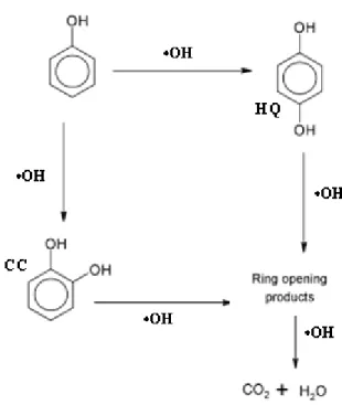
4.1.1. Intermediates of phenol photodegradation………... 50
4.2. Dyes……….... 53
5. Kinetic models for photocatalysis process ………... 55
5.1. Langmuir-Hinshelwood kinetic model……… 55
5.2. First-order kinetic model………. 56
CHAPTER II: MATERIALS AND METHODS 1. The model molecules, materials and oxidizing agents……….. 57
1.1. Phenol and three substituted phenols……….. 57
1.2.Tartrazine………. 59
ix
1.4. The Ahlstrom tissues……….. 61
a. Materials used for tissue production……….. 61
b. Types of media used………... 62
1.5. Activated carbon coated by TiO2……… 65
2. Analytical techniques………... 65
2.1. Analytical methods for liquid solutions………... 65
2.1.1. High Performance Liquid Phase Chromatography or HPLC……….. 65
2.1.2. Global Measures of the organic pollutants……….. 69
a. Chemical Oxygen Demand: COD ………. 69
b. Colorimetric method for the measurement of COD (Method Hach 8000)……… 70
c. COD: Operating protocol ……….. 70
d. Standard method for the measure of TOC………. 71
2.2. Characterisation methods of the activated carbons………. 72
2.2.1. Textural properties………... 72
2.2.1.1. Gas porosimeter……….... 72
2.2.1.2. The helium pycnometer………. 74
2.2.2. Structural properties………. 75
a. Elemental analysis CHNSO……… 75
b. Ash content………... 77
c. Metal content by ICP-AES………. 77
d. The thermogravimetric analysis (TGA)………. 78
2.2.3. Chemical surface properties………. 78
a. Boehm titration……….. 78
b. pH at the point of zero charge……….. 79
c. SEM/EDX ………. 79
3. The experimental studies………. 80
3.1. Device for isotherm: the multifunction thermostatic bath……….. 80
3.1.1. Operating protocol ……….. 80
3.1.2. Adsorption equilibrium studies……… 81
a. Monocomponent isotherms……… 81
b. Multicomponent isotherms……… 81
3.2. Study the effects of various parameters on the adsorption………. 81
a. Influence of pH on phenols adsorption……….. 81
b. Influence of salt addition on phenols adsorption……… 82
c. Influence of temperature on phenols adsorption……… 82
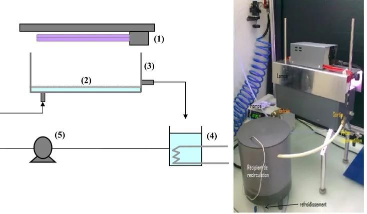
3.3. The photocatalytic “channel” reactor………. 82
x
3.6. Radiometer……… 91
CHAPTER III: ADSORPTION OF PHENOLS ONTO DIFFERENT ACTIVATED CARBONS 1. Introduction………. 92
2. The adsorbents : commercial activated carbons and sewage based activated carbons………. 92
2.1. Textural properties: Specific surface area and pore volume………... 92
2.2. Chemical analysis of the activated carbons……… 94
2.2.1. Elemental analysis and ash content………. 94
2.2.2. CHNSO analysis……….. 95
2.3. Chemical analysis of the surface………. 95
2.3.1. pH………... 95
2.3.2. Boehm titration: surface functions……….. 96
2.3.3. Thermogravimetric analysis (TGA)……… 97
3. Preliminary study: Effect of different experimental factors on phenols adsorption onto activated carbon ……….. 100
3.1. Effect of solution pH ……….. 100
3.2. Effect of an inorganic salt: NaCl ……… 102
3.3. Effect of temperature………... 104
4. Adsorption performance of activated carbons of various origins………... 105
4.1 Single component system……… 105
4.1.1 Screening of different activated carbons: phenol as reference model……….. 105
4.1.2. Model application for phenol adsorption………. 106
4.1.3. Adsorption of different substituted phenols onto S23, F22 and SA_DRAW…….. 107
a-Single solute solution Isotherm……….. 107
b- Langmuir and Freundlich models……….. 110
4.2. Competitive adsorption of P, PHBA, PCP and PNP……….. 111
5.Conclusion……….. 115
CHAPTE IV:PHOTOCATALYTIC OXIDATION A- Oxidation using tissue………. 116
1. Introduction……….. 116
2. Characterization of materials………. 117
2.1. Surface area and porosity……… 117
xi
3. Adsorption isotherms……….. 122
3.1. Comparison of the adsorption isotherms of different adsorbents………... 122
3.2. Comparison of the Langmuir and Freundlich models parameters ………. 123
4. Kinetics of adsorption and photocatalytic oxidation of phenol onto AC media…. 125 4.1. Direct photolysis of phenol onto AC media……… 126
4.1.1. Control test ……….. 126
4.1.2. Quantity of adsorbed phenol during successive cycles ……….. 130
4.2. Evolution of physical properties of AC media……… 131
4.2.1. BET surface area and pore size distribution……… 131
4.2.2. Thermogravimetric Analysis ……….. 132
5. Kinetics of adsorption and photocatalytic oxidation of phenol onto AC / TiO2 tissue………... 133
5.1. Adsorption step of phenol onto tissue………. 133
5.1.1. Kinetic adsorption cycles of phenol onto tissue………... 133
5.1.2. The adsorbed phenol quantity during the adsorption cycles……… 137
5.2. Photodegradation step of phenol onto tissue………... 141
5.2.1. Kinetics of photodegradation cycles of phenol onto tissue……….. 142
5.2.2. Regeneration efficiency ………... 146
5.2.3. Kinetic model for photodegradation of phenol ………... 148
5.2.4. Chemical Oxygen Demand ………. 152
5.3. Physical properties of activated carbon in the tissue ………. 155
5.3.1. BET surface area and pore-size distribution……… 155
5.3.2. Thermogravimetric analysis ………. 157
6. Effect of H2O2 addition on the photocatalytic degradation of phenol…………... 159
6.1. The operating conditions: quantity of H2O2……… 159
6.2. Control test……….. 160
6.3. Kinetics of adsorption and photocatalytic oxidation of phenol onto tissue with H2O2 addition ……… 161
6.3.1. Evolution of adsorption step ……….. 161
6.3.2. Photodegradation step………... 162
a. Kinetic of photodegradation cycles of phenol ………. 162
b. Model application for photodegradation of phenol in the presence of H2O2……… 165
xii
6.3.5. Photo-mineralization of phenol in the presence of H2O2 ……… 169
6.4. Evolution of physical properties of activated carbon in the tissue ……… 173
6.4.1. BET surface area and pore-size ………... 173
6.4.2. Thermogravimetric analysis ……… 173
7. Photocatalytic oxidation of phenol using fixed bed continuous reactor ………… 175
B. Photocatalytic degradation of Tartrazine using immobilized TiO2 on activated carbon S23………. 180
1. Photocatalysis using TiO2 deposited on activated carbon: AC/TiO2……… 181
1.1. Materials ………. 181
1.2. Characterization of AC / TiO2 sample………. 181
1.2.1. Electron microscopic analysis ………. 182
1.2.2. Energy dispersive X-ray microanalyses (EDX)………... 182
1.2.3. Physical properties………... 185
1.2.4. Thermal gravimetric analysis……….. 186
1.3. Adsorption isotherms………. 186
1.4. Photolysis and photocatalysis of Tartrazine ………. 188
1.4.1. Adsorption / photocatalytc oxidation cycles……… 191
2. Photocatalytic oxidation of Tartrazine ……… 195
2.1. Kinetic of Tartrazine photodegradation cycles ………. 195
2.2. Regeneration efficiency……….. 198
2.3. Photocatalytic mineralization of Tartrazine……… 198
2.4.Physical properties of activated carbon after the oxidation cycles of Tartrazine ……… 201
2.4.1. BET surface area and pore-size distribution………... 201
2.4.2. Thermogravimetric analysis………. 202
3. Conclusions……….. 204
CHAPTER V: CONCLUSIONS AND FUTURE WORK……… 205
REFERENCES ……… 208 ANNEXES
xiii Page
Fig.I-1: Schema of the mechanism of molecule adsorption using microporous
adsorbent (Tchobanoglous et al., 2003)……….. 7
Fig.I-2: Schematic representation of different types of pores………. 8
Fig.I-3: Schematic representation of external and internal adsorbent surface…. 8 Fig.I-4: Schema of the process of activated carbon manufacturing………. 10
Fig.I-5: Arrangement of carbon atoms in graphite crystal (a); microstructure of the activated carbon (b)………... 12
Fig.I-6: Surface functional groups of the activated carbon………... 13
Fig.I-7: Molecules studied by Gokturk and Kaluc (2008)………... 17
Fig.I-8: Classification of adsorption isotherms……… 22
Fig.I-9: Suitability of water treatment technologies according to the Chemical Oxygen Demand, COD (Andreozzi et al., 1999)……….. 29
Fig.I10: Main advanced oxidation processes (AOP)……….. 29
Fig.I-11: Configuration of the electronic bands of conductor, semi-conductor and insulator materials……… 33
Fig. I-12: Crystallographic forms of TiO2: (a): anatase; (b): rutile; (c): brookite... 35
Fig.I-13: Formation of hydroxyl radicals and superoxide ions on the TiO2 surface (Huchon, 2002)………... 36
Fig.I-14: Influence of the mass of catalyst on the reaction rate, r……….. 43
Fig.I-15: Role of AC in the enhanced activity of TiO2 (Liu et al., 2007)……... 46
Fig.I-16: A possible reaction mechanism of phenol oxidation in the presence of illuminated TiO2……….. 52
Fig. I-17: Reaction pathway for the wet oxidation of phenol with AC in presence of hydrogen peroxide……….. 52
Fig. I-18: Scheme route for phenol oxidation by Fenton’s reagent………. 53
Fig.II-1: Schematic representation of media AC………... 62
Fig.II-2: Schematic representation of media AC / TiO2, composition and photo……… 63
Fig.II-3: Schematic representation of media TiO2, composition and photo…….. 64
Fig.II-4: Schematic diagram of the principal technique of HPLC………. 66
Fig.II-5: Thermostatic oven DRB 200 and spectrophotometer DR/2500……….. 71
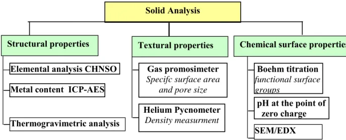
Fig. II-6: The different techniques of analysis for solid characterization………... 72
Fig.II.7: Simplified functional diagram of helium pycnometer……… 74
Fig.II-8: Schema of the elemental analyser for CHNS analyses………... 76
Fig.II-9: Schematic representation of the classification of Boehm titration……. 78
Fig.II-10: Static multifunction thermostatic bath used for the adsorption isotherm……….. 80
Fig. II -11: Schematic representation and photography of the channel reactor……. 82
Fig.II-12: Schematic and photography of the thermostated cylindrical reactor….. 86
Fig.II-13: Photography of the fixed bed photocatalytic reactor……….. 89
Fig. III-1: Thermogravimetric analysis of the two commercial activated carbons.. 98
Fig. III-2: Thermogravimetric analysis of the sludge based activated carbons….. 99
xiv
Fig.III-4: Effect of NaCl addition on the adsorption of P (a) and PHBA (b) onto
AC S23 at 25°C (pH = 6.3 for P and 3.5 for PHBA)……….. 103
Fig. III-5: Effect of different temperatures on the adsorption of P (a) and PHBA
(b) onto AC S23 (pH = 6.3 for P and 3.5 for PHBA)………. 104
Fig. III-6: Adsorption isotherms of phenol onto different activated carbon
materials at 25 °C (experimental data : symbols, Langmuir model:
lines and Freundlich model: dotted lines)………... 105
Fig.III-7: Adsorption isotherms at 25°C of single component of phenol, PHBA,
p-nitrophenol and p-chlorophenol onto activated carbons (a)
SA_DRAW, (b) S23 and (c) F22. ……….. 108
Fig. III-8: Comparison of experimental data of adsorption isotherms with the
calculated data by Langmuir- Freundlich model for equimolar mixture of phenol, PHBA, p-nitrophenol and p-chlorophenol onto SA_DRAW
(a), S23 (b) and F22 (c) at 25 °C………. 114
Fig. IV-1: SEM image of the original granular AC (x350, left and x 3000, right).. 118
Fig. IV-2: SEM image of AC in TiO2 / AC tissue (x350, left and x 3000, right)… 118
Fig. IV-3: SEM image of the surface of TiO2 media (x 1000, right) (Thevenet et
al., 2005)………. 119
Fig IV-4: Cross sectional SEM of the original granular AC (a) and AC in the
TiO2/AC tissue (b; Region I & Region II) in which two different
regions are pointed out……… 120
Fig. IV-5: EDX diagrams of the original granular AC (a) and AC in the TiO2/AC
tissue in two different regions (b; Region I & Region II)………... 120
Fig. IV- 6: Thermogravimetric analysis of the original granular AC………... 121
Fig. IV-7: Adsorption isotherms of phenol onto original granular AC, AC media,
TiO2/ AC tissue and TiO2 media at 25 °C……….. 122
Fig. IV-8: Schematic representation of one cycle of the sequential process……... 125
Fig. IV-9: Adsorption /UV irradiation cycles of phenol (C0 = 0.88 g/L) onto
activated carbon media at 25 °C………. 127
Fig. IV-10: Adsorption cycles of phenol (C0 = 0.88 g/L) onto activated carbon
media at 25°C………. 128
Fig. IV-11: Evolution of phenol concentration under UV irradiation during 4
cycles of photo-oxidation onto AC media at 25 °C (C0 = 0.88 g/L)…. 128
Fig. IV-12: Photolysis of phenol without activated carbon at 25 °C……… 128
Fig. IV-13: Comparison of the quantity of adsorbed phenol during the cycles of adsorption ( ) for AC media ( : sum of the adsorbed quantities of
phenol from cycle 1 to cycle 4, q isotherm)………. 130
Fig. IV-14: Comparison of thermogravimetric analysis of AC media; used AC
after phenol adsorption and UV irradiation and non used AC………… 132
Fig. IV-15: Adsorption and photocatalytic oxidation cycles of phenol (C0 = 0.88
g/L) onto TiO2/AC tissue at 25 °C………. 134
xv
Fig.IV-18: Comparison of the quantity of adsorbed phenol during the cycles of adsorption ( ) onto tissue ( : sum of the adsorbed quantities of
phenol, q isotherm, qestimated estimated quantity of phenol) for
initial phenol concentrations of 0.88 g/L (a) and 0.45 g/L (b)………… 136
Fig.IV-19: Kinetic of the phenol oxidation cycles onto TiO2/AC tissue using two
different initial phenol concentrations; 0.88 g/L (a) and 0.45 g/L (b)… 138
Fig.IV-20: Comparison of the phenol degradation kinetic for the two different initial phenol concentrations during the first cycle of the
photocatalytic oxidation……….. 144
Fig. IV-21: Effect of the initial phenol concentration on the regeneration
efficiency during photocatalytic degradation runs onto tissue………… 145
Fig.IV-22: Comparison between the experimental (symbols) and theoretical (lines) data during the photocatalytic degradation cycles of phenol
onto tissue [T: 25 °C, C0; 0.45 g/L (a) and 0.88 g/L (b)]. The lines
represent the values calculated from the kinetic model of pseudo first
order……… 147
Fig.IV-23: Comparison of apparent rate constant (Kap) between two different
initial phenol concentrations during the photocatalytic oxidation runs
onto tissue……… 150
Fig. IV-24: Kinetics of the photocatalytic disappearance of COD during phenol
removal (C0 = 0.88 g/L)……….. 151
Fig. IV-25: Evolution of COD initial and final during 4 photocatalytic oxidation
cycles of tissue as compared to the COD final of phenol (C0 = 0.88
g/L)……….. 153
Fig.IV-26: Comparison between the COD experimental (symbols) and theoretical (lines) data during the photocatalytic degradation cycles of phenol
onto tissue within 120 min (T: 25 °C, Ci; 0.88 g/L). The lines
represent the values calculated from the kinetic model of pseudo first
order……… 155
Fig.IV-27: Comparison of thermogravimetric analysis of the activated carbon in Ahlstrom tissue; used AC (at the end of consecutive oxidation runs
without cleaning, rinsed with H2O, and cleaning with acetonitrile/US)
and non used AC using two initial phenol concentrations; 0.88 (a) and
0.45 g/L (b)……….. 158
Fig.IV-28: Kinetic of phenol removal by UV/H2O2 and TiO2 media at 25 °C (Ci
phenol = 0.88 g/L, V H2O2= 50 ml)……….. 160
Fig.IV-29: Kinetics of phenol adsorption cycles onto tissue at 25 °C. ……… 162
Fig.IV-30: Comparison of the quantity of adsorbed phenol ( ) during the cycles of adsorption onto tissue ( : sum of the adsorbed quantities of phenol from cycle 1 to cycle 6, : sum of the adsorbed quantities of
phenol without H2O2, : q isotherm). ………. 162
xvi
Fig.IV-32: Comparison between the experimental (symbols) and theoretical (lines) data during the photocatalytic degradation cycles of phenol
onto tissue in the presence of H2O2 (T: 25 °C, C0; 0.88 g/L). ………… 166
Fig. IV-33: Comparison between the regeneration efficiency of tissue (AC/TiO2)
during the photocatalytic degradation runs in the presence and absence
of H2O2……….. 168
Fig. IV-34: Total Organic Carbon (TOC) removal from the solution during 5
cycles of photocatalytic degradation of phenol by tissue (TiO2/AC) in
the presence of H2O2………. 169
Fig. IV-35: Comparison between TOCinitial, at the beginning of oxidation (t = 0)
and TOCfinal, at the end of the oxidation process and the TOC
calculated from oxalic (TOC f,oxalic) and phenol concentration at the
end of reaction (TOC f,phenol) during 5 photocatalytic oxidation cycles
by TiO2 in tissue in the presence of H2O2……….. 171
Fig.IV-36: Comparison between TOC values of the experimental (symbols) and theoretical (lines) data during the photocatalytic degradation cycles of
phenol onto tissue within 360 min in the presence of H2O2 (T: 25 °C,
C0; 0.88 g/L)……… 172
Fig. IV-37: Comparison of thermogravimetric analysis of the activated carbon in tissue; used AC (at the end of 5 consecutive cycles in the presence of
H2O2) and virgin AC……….. 174
Fig.IV-38: Kinetic adsorption of phenol (Ci = 0.2 g/l) onto TiO2/AC tissue (12.7
g) at 25 °C. ………. 176
Fig.IV-39: Continuous photocatalytic oxidation of phenol in fixed bed type
reactor (TiO2/AC tissue) at 25°C (Ci =0.0179 g/L, flow rate= 2 ml/min
) mass of tissue = 12.7 g)……… 176
Fig.IV-40 : Comparison between the experimental (symbols) and theoretical
(lines) data of phenol photodegradation using TiO2/AC tissue in fixed
bed reactor (T: 25 °C, Ci; 0.0179 g/L)……… 178
Fig. IV-41: SEM image of AC (a) and AC/TiO2 (b)……….. 182
Fig.IV-42: Cross sectional SEM of AC (a) and AC/TiO2 (b I & b II) sample in
which two different regions are pointed out………... 183
Fig.IV-43: EDX diagrams of AC (a) and AC/TiO2 composite (b I & b II),
obtained in two different regions: region I (b I) and region II (b II)….. 184
Fig.IV-44: Thermal gravimetric analysis of the original AC S23 and AC/ TiO2
composite………. 186
Fig.IV-45: Isotherms of Tartrazine adsorption onto suspension mixture of AC -
TiO2 and onto TiO2 deposited onto AC at 25 °C……… 187
Fig.IV-46: Direct photolysis of Tartrazine using UV irradiation at 25 °C (photon
flux; 47.5 W/m2, Treated volume = 1L)……….. 189
Fig.IV-47: Kinetics of Tartrazine adsorption in the dark onto TiO2 catalyst at 25
°C. ……….. 190
Fig.IV-48: Kinetic of Tartrazine photodegradation by TiO2 catalyst under UV
irradiation at 25 °C (photon flux; 47.5 W/m2)……… 190
Fig.IV-49: Kinetic of Tartrazine adsorption cycles onto AC-S23 + TiO2 mixture
at 25 °C……… 192
Fig.IV-50: Kinetic of Tartrazine adsorption cycles onto AC /TiO2 composite at 25
xvii
(CVD)………. 193
Fig.IV-52: Comparison of the quantity of adsorbed Tartrazine during the cycles
of adsorption for AC / TiO2 composite ( ), a mixture of AC +TiO2
( ) and the estimated adsorbed quantity for AC/TiO2 composite;
assuming that only the adsorption process occurs ( ) at 25°C….. 193
Fig. IV-53: Kinetics of Tartrazine photocatalytic degradation cycles using solid
mixture of AC and TiO2 (photon flux: 47.5 W/m2)………. 197
Fig.IV-54: Kinetics of Tartrazine photocatalytic degradation cycles using AC/
TiO2 composite (photon flux: 47.5 W/m2)……….. 197
Fig. IV-55: Comparison of the regeneration efficiency of suspension mixture of
AC - TiO2 and AC/TiO2 composite……… 198
Fig.IV-56: Total Organic Carbon (TOC) remaining in the solution during 5 cycles of photocatalytic degradation of Tartrazine by the suspension mixture
of TiO2 and AC……… 199
Fig.IV-57: Total Organic Carbon (TOC) remaining in the solution during 4 cycles
of photocatalytic degradation of Tartrazine by AC/ TiO2
composite……… 200
Fig. IV-58: Comparison between final TOCremoval by the suspension mixture of
AC - TiO2 and that by the AC/ TiO2 composite during 4 photocatalytic
oxidation cycles of Tartrazine………. 200
Fig.IV-59: Comparison between TGA of virgin AC/TiO2 and used AC/TiO2
xviii Page
Table I-1 : IUPAC classification of pore sizes………. 7
Table I-2: Some examples of monocomponent isotherms models………. 25
Table I-3 List of homogeneous AOPs ……….. 31
Table I-4: Band gap energy and wavelength sensitivity of semiconductors (Stumm, 1992)………... 32
Table I-5: Mechanism steps of photochemical oxidation reaction on the TiO2 surface……….. 37
Table I-6: Photocatalytic degradation of different organic compounds by heterogeneous photocatalysis (Gaya et al., 2008)……… 49
Table II-1: The physico-chemical properties of phenols studied………... 58
Table II-2: The physico-chemical properties of tartrazine ……… 59
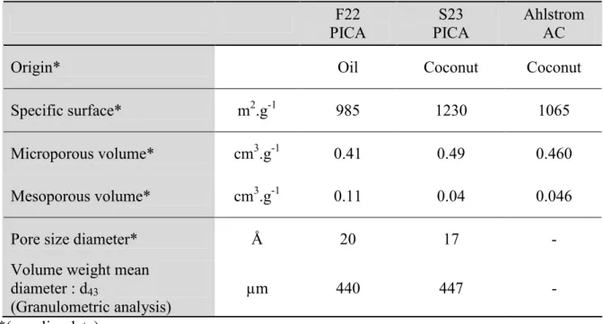
Table II-3: Main characteristics of commercial activated carbons studied……… 60
Table II-4: Activated carbons resulting from the pyrolysis of municipal stations of sewage sludges………. 61
Table II-5: Composition of the activated carbon media………. 63
Table II-6: Composition of the media AC / TiO2……….. 64
Table II-7: Composition of the media TiO2………... 64
Table II-8: Methods of separation by HPLC for the pollutants during the adsorption process……… 68
Table II-9: Methods of separation by HPLC for the pollutants during the oxidation process………... 68
Table II-10: Main elements of the channel reactor……….. 83
Table II-11: Operating conditions of adsorption/photocatalysis cycles with the channel reactor ……… 85
Table II-12: Operating conditions of adsorption/photocatalysis cycles into glass photocatalytic reactor……….. 88
Table II-13: The experimental conditions of adsorption / photocatalysis runs into fixed bed photocatalytic reactor……….. 90
Table III-1: Comparison between the textural physical properties of two commercial and six sludge based activated carbons ………... 93
Table III.2: Metal composition analysis of the activated carbons estimated by ICP-AES……….. 94
Table III-3: Elemental analysis of the activated carbons………. 95
Table III-4: Values of pHPZC andpH of contact for the activated carbons……….. 96
Table III-5: Results of Boehm titration……….. 97
Table III-6: Parameters of Langmuir and Freundlich models for the adsorption of phenol on the all studied activated carbons at 25 °C……… 106
xix
Table III-8: Parameters of Langmuir and Freundlich models for the adsorption of
single solute of P, PCP, PNP and PHBA on three types of activated
carbons at 25 °C ………. 111
Table IV-1: Apparent surface area and pore volume distribution of AC powder
and TiO2 media……… 118
Table IV-2: EDX elemental composition of the original granular AC and AC in
TiO2 /AC tissue, in two different regions as indicated in Fig. IV-4… 119
Table IV-3: Parameter constants of Langmuir and Freundlich models for phenol
adsorption……… 125
Table IV-4: Physical properties of AC media (before and after adsorption/UV
cycles)………. 131
Fig. IV-5: Adsorption and photocatalytic oxidation cycles of phenol (C0 = 0.45
g/L) onto TiO2/AC tissue at 25 °C……… ……. 135
Table IV-6: Evolution of the phenol adsorption percentages (based on the
decrease in concentration) during the adsorption cycles using two
phenol concentrations onto TiO2/ AC tissue……… 149
Table IV-7: Pseudo first-order apparent constants (Kap) and correlation
coefficients (R2) corresponding to different initial phenol
concentrations (0.45 g/L and 0.88 g/L, before dark adsorption)
during the consecutive photocatalytic oxidation runs………... 154
Table IV-8: Pseudo first-order apparent constants (Kap) and correlation
coefficients (R2) detected in COD removal during the consecutive
photocatalytic oxidation runs; Ci phenol (0.88 g/L)……… 156
Table IV-8: Comparison of physical properties of used (5 cycles) and virgin AC
in the tissue with two initial phenol concentrations; 0.88 and 0.45
g/L………. 156
Table IV-9: Pseudo first-order apparent constants (Kap) and correlation
coefficients (R2) during the consecutive phenol photocatalytic
oxidation runs in the presence of H2O2……… 165
Table IV-10: Apparent first order rate constants detected in the photodegradation
of phenol by UV irradiation of tissue (TiO2/AC) and Synergetic
factor (S) in the presence and in the absence of H2O2.……… 167
Table IV-11: Pseudo first-order apparent constants (Kap) and correlation
coefficients (R2) for TOC removal during the consecutive phenol
photocatalytic oxidation runs in the presence of H2O2……… 172
Table IV-12: Comparison of physical properties of used AC in the tissue after the
5 adsorption-regeneration cycles with and without H2O2 addition and
virgin AC……….. 173
Table IV-13: The values of the apparent rate constant (kap) and correlation
coefficient (R2) of the first order model for phenol photocatalytic
oxidation onto tissue in fixed bed reactor ………... 178
Table IV-14: EDX elemental composition of AC and TiO2 /AC composite, in two
different regions as indicated in Fig .IV-42………. 183
xx
Table IV-17: Parameter constants of Langmuir and Freundlich models for
Tartrazine ……… 188
Table IV-18: Comparison of the of Tartrazine adsorbed quantity during the cycles
of adsorption for AC / TiO2 composite, a mixture of AC +TiO2 and
the estimated adsorbed quantity for AC/TiO2 composite ……… 194
Table IV-19: Physical properties of AC in both studied systems; AC/ TiO2
composite and suspension mixture of TiO2 and AC as compared to
xxi
AC Activated carbon
AOP Advanced oxidation
BET Brunauer, Emmet and Teller
B.J.H. Barrett, Joyner and Halenda
Ce Concentration at equilibrium (g.L-1)
Ci Initial liquid-phase concentration of solute
C’ Adsorption constant of gaz used (-).
C_DMAD Carbonised Dewatered Mesophilic Anaerobically Digested sludge
C_DRAW Carbonised Dewatered Raw sludge
CHNSO Carbon, Hydrogen, Nitrogen, Sulfer, Oxygen,
CO2A_DSBS CO2 Activated Dewatered Secondary Biological Sludge
CODeq Chemical Oxygen Demand at equilibrium (mg.L-1)
d diameter of pores
EDX Energy Dispersive X-ray analysis
HPLC High Performance Liquid Phase Chromatography
ICL Imperial College of London
IUPAC International Union Pure Applied Chemistry
kap Constant of first order model
Kf Freundlich constant (L.mg-1.g-1)
KL Langmuir constant (L.g-1)
2 O
M
Molecular mass of oxygen (g.mol-1)e d c b aH N O Cl C
M
Molecular mass of compound CaHbNcOdCle (g.mol-1)
msolid Mass of solid sample
n Freundlich constant
NA Avogadro number (mol-1)
p Adsorption equilibrium pressure (Pa)
xxii
qe Adsorbed quantity at equilibrium
qmax Maximum adsorbed quantity
R2 Coefficient constant
SBET Specific surface of solid
SEM Scanning Electron Microscopy
TGA Thermogravimetric analysis
TOC Total organic carbon
UV Ultra-Violet
V Volume
Vm Volume of the gaz necessary to form a complete monolayer on the
surface (m3)
Vmol Molecular volume of gaz (m3.mol-1)
PAHB P-hydroxybenzoic Acid
PCP p-chlorophenol
PCM Physico-Chemical Mixture
PNP p-nitrophenol
ph Phenol
SA_DMAD Steam Activated Dewatered Mesophilic Anaerobically Digested sludge
SA_DRAW Steam Activated Dewatered Raw sludge
SBAC log Kow
Sewage Sludge based activated carbon the octanol-water partition coefficient
1
General Introduction
Sustainable water supply is an increasing demand in today’s word. In addition to water amounts needed for agriculture, water quality is fundamental for human life and the whole earth ecology. Among the wide variety of problems concerning water the reduction of pollution is a major issue. Water treatments are most often based on biological processes which are now conveniently installed in all the developed countries. The main remaining problem concerns non biodegradable compounds most often coming from industrial or agricultural activities. Besides very harmful dissolved heavy metal, most of these pollutants are organics, and may be very dangerous for human health.
Other processes should then been implemented, before or after biological treatments, depending on the toxicity for the microorganisms achieving biological treatments, and concentrations of the non biodegradable pollutants.
Adsorption on activated carbon for achieving high water purification is very widely used, and most often as a post treatment as its cost would be excessive for concentrated pollution (Dabrowski et al, 2005; Fierro et al., 2008; Pan et al., 2008; Ahmed et al., 2010). Indeed while adsorption on activated carbon is a very efficient technique to reduce organic pollution of water, convenient and cheap regeneration of the adsorbent is the main issue concerning adsorption economy. For most applications regeneration is achieved in few special plants at high temperature (>900°C) where about 15% of the initial activated carbon is lost. In the case of industrial wastewaters, due to possible hazardous products, this technique is not allowed and the saturated activated carbon becomes itself a waste, leading to restricted use of this adsorption technique to very low pollutant concentration.
Besides adsorption many recent developments concern chemical oxidative treatments, from the simple hydrothermal treatment needing high temperature and pressure, wet air oxidation (WAO), or its catalytic version (CWAO) at milder conditions, to much more efficient oxidations performed at room temperature and often called “Advanced Oxidation Processes” (AOP). These AOP generally use stronger oxidant than oxygen, like ozone and specially OH radicals, generated either by UV, photocatalysis, Fenton reagent, or electrochemistry at a convenient potential (Vora et al., 2009; Ahmed et al., 2011).
2 The team “Multiphase Reactions and Reactors”, at “Laboratoire de Génie Chimique” Toulouse, has been engaged for many years on these topics starting with oxidation by ozone and pressurized air then by Fenton and photo Fenton processes and by electrochemistry. Recently a sequential process coupling adsorption and oxidation (AD-OX process) was proposed (Krou, 2010): Pollutants are adsorbed in the first step providing purified water, then the batch oxidative step achieves simultaneously “in situ” the degradation of the adsorbed pollutants and the regeneration of the adsorbent. The oxidative step is catalyzed by the activated carbon playing successively the role of adsorbent and of catalyst of its own regeneration under moderate pressure and temperature. Despite its very attractive concept this process suffers two major drawbacks : i) corrosion due to Cl- ions often present in wastewater
is extremely severe at 150°C, ii) activated carbon cannot be conveniently regenerated when phenolic compounds are concerned due to oxidative coupling (or oligomerization) occurring in presence of dissolved oxygen, especially at the temperature requested by oxidation. These oligomerized phenolic compounds are chemisorbed and then very difficult to degrade, leading to pore clogging and dramatic reduction of activated carbon surface area.
Clearly better results were found with Fenton and even better with photo Fenton oxidative regeneration (Muranaka et al., 2010). Nevertheless Fenton process needs addition of iron ions as catalyst, which is undesired in the treated water, and hydrogen peroxide which is consumed being a significant cost in this process.
Another oxidative technique able to perform activated carbon regeneration at low temperature and low operation and investment cost could be photocatalysis with TiO2 as both
catalyst and UV lamps are not expensive. Nevertheless the dramatic development of investigations on photocatalytic processes is probably partly due to its intrinsic sustainability when prospecting solar energy as the only consumption, if the photocatalyst is conveniently maintained (Zhanga et al., 2011).
The aim of this work is to start to investigate the extension of the AD-OX process to photocatalysis expecting to maintain the high separation quality of adsorption on activated carbon and to improve the regeneration when using photocatalysis instead of pressurised air. It should be recalled that in AD-OX concept, contrary to AOP, the water treatment is not achieved by oxidation but by adsorption, the oxidative step being needed only for pollutant degradation and subsequent activated carbon regeneration.
3 Then this work will be divided into two main parts:
• Adsorption on activated carbons, including two commercial activated carbons and also new activated carbonaceous materials prepared from sewage sludge. As wastewater is most often composed of a mixture of pollutants we have also investigated model mixtures of phenolic compounds. In addition a more complex pollutant, tartrazine has also been investigated.
• Photocatalytic regeneration of activated carbon, using several photocatalytic media, available commercially or prepared at LGC. Due to their different shape (sheets or powders) they have to be operated in different types of reactors. The efficiency of this oxidative step is investigated within two aspects: i) pollutant and COD degradation during photocatalysis, and moreover ii) re-adsorption on the regenerated activated carbon. These two steps will be carried out several times during successive Adsorption-Oxidation cycles.
An important analytical work is required both for liquid and especially solid evolution during the two steps and the recycles. A special chapter has been dedicated to these analyses and to experimental methods.
The manuscript is then divided into four parts: -Literature review
-Materials and methods -Adsorption
-Photocatalysis
NB. This work being part of three research projects it has been constrained on several aspects: choice of activated carbons (ANR-PRECODD-PHARE), of sludge based activated carbons (EU Project REMOVALS-STREP-6th FP), of dye pollutant (tartrazine) (CTP - Région Midi
4
Work Accomplished
The work done in this study has been presented in five chapters as discussed in the
following text. The study begins with the literature review in chapter I. Literature of various types of toxic pollutants present in water; phenols, dyes, adsorption process, different adsorbents, activated carbon, advanced oxidation, photocatalytic degradation, mechanism of photosensitization of TiO2 under UV have been summarized in this chapter.
In chapter II experimental procedures, description of reactors, instruments used and analytical techniques are discussed in details.
Chapter III, Adsorption of phenols onto different activated carbons, it includes study
and compare two groups of different ACs; the first group was six sewage sludge based activated carbons (SBACs) produced from different sludge raw materials. The second group was two commercial activated carbons (PICA S23 and F22). Firstly, the physical and chemical properties of two groups of ACs were fully studied in order to understand the different between all the ACs studied. Secondly, scanning of the adsorption performance of all this ACs was investigated by using phenol compound as reference model. Thirdly among the six sewage sludge based ACs, we select that of the highest phenol adsorption capacity for the next study. In this part, we compare the performance of these SBACs with the two commercial ACs in both the single- and multi-component adsorption using phenol (P), p-chlorophenol (PCP); p-nitrophenol (PNP) and p-hydroxy benzoic acid (PHBA) as pollutants. The application of different isotherm models lik Langmuir and Freundlich have been also investigated. The effect of different experimental parameters on the adsorption process such as effect of solution pH; effect of the presence of inorganic salt NaCl and effect of temperature have been also studied.
In Chapter IV, Photocatalytic oxidation, it includes two parts, in Part A, phenol degradation of two initial concentrations has been carried out in the presence of UV using different Ahlstrom Medias (tissues) in a “channel” type photo reactor. The kinetic degradation of phenol concentration with the time was investigated. Furthermore, the effect of this oxidation process on activated carbon regeneration and the effect addition of electron acceptors such as H2O2 were also studied. The degradation was studied by monitoring the
change in substrate concentration employing HPLC analysis. The mineralisation of phenol was also determined by TOC and COD analysis. To study the effect of this type of oxidation on the AC properties, TGA and BET analyses were studied at the end of cycles and compared with the virgin one.
5 In Part B, the degradation of tartrazine as an alimentary dye was investigated using another coupled material of AC/TiO2 prepared by Chemical Vapour Deposition (CVD)
technique. As we studied with the AC/TiO2 tissue, in this part, the performance of the
AC/TiO2 composite was investigated by following the decrease in tartrazine concentration
with the time during all the adsorption and oxidation runs. The regeneration efficacy of the AC/TiO2 composite was also studied. The TOC was also evaluated during the oxidation
cycles. TGA and BET analysis were studied after the cycles and compared with the virgin one. Similar studies using a suspension mixture of commercial TiO2 PC500 and AC S23
powders were compared to those found with the AC/TiO2 composite.
CHAPTER I
A. Adsorption
1. Fundamentals of the adsorption 1.1. General definition of adsorption
Adsorption is a process in which a substance (adsorbate), in gas or liquid phase, accumulates on a solid surface. It is based on the capability of porous materials with large surfaces to selectively retain compounds on the surface of the solid (adsorbent). There are two types of adsorption; physical and chemical adsorptions.
1.1.1. Physical Adsorption
Physical adsorption is achieved by Van der Waals forces, dipole interactions, and hydrogen binding. There is no electron exchange between adsorbent and adsorbate. Because there is no activation energy required for physical adsorption, the time needed to reach equilibrium is very short. Physical adsorption is a non–specific and a reversible process.
1.1.2. Chemical Adsorption
Chemical adsorption results from the chemical link between adsorbent and adsorbate molecule, therefore it is specific as well as irreversible and chemical as well as electronic properties of adsorbent are changed. Binding between adsorbent and adsorbate by covalent bond is called weak chemical adsorption, and that by ionic bonds is called strong chemical adsorption.
1.2 Adsorption Mechanisms
The adsorption process of the adsorbate molecules from the bulk liquid phase into the adsorbent surface is presumed to involve the following stages (Fig.I-1):
1. Mass transfer of the adsorbate molecules across the external boundary layer towards the solid particle.
2. Adsorbate molecules transport from the particle surface into the active sites by diffusion within the pore–filled liquid and migrate along the solid surface of the pore. 3. Solute molecules adsorbtion on the active sites on the interior surfaces of the pores. 4. Once the molecule adsorbed, it may migrate on the pore surface trough surface diffusion.
7
Fig.I-1. Schema of the mechanism of molecule adsorption using microporous adsorbent
(Tchobanoglous et al., 2003).
1.3. Physical properties of the adsorbent
The most important property of adsorbent, which determines its usage, is the pore structure and the specific surface area.
1.3.1. Adsorbent pores
The total number of pores, their shape and size determine the adsorption capacity and even the dynamic adsorption rate of the adsorbent. The range of pore sizes which is defined according to the International Union of Pure and Applied Chemistry (IUPAC) is summarized in Table I-1 (Rodriguez-Reinoso and Linares-Solano, 1989). A schematic representation of the porous structure of adsorbent is shown in Figure I-2.
Table I-1
IUPAC classification of pore sizes
Pores Pore width ( W;nm)
Ultramicropores W < 0.7nm
Supermicropores 0.7 < W< 2nm
Micropores W < 0.2
Mesopores 2-50