HAL Id: hal-02991443
https://hal.mines-ales.fr/hal-02991443
Submitted on 13 Nov 2020
HAL is a multi-disciplinary open access
archive for the deposit and dissemination of
sci-entific research documents, whether they are
pub-lished or not. The documents may come from
teaching and research institutions in France or
abroad, or from public or private research centers.
L’archive ouverte pluridisciplinaire HAL, est
destinée au dépôt et à la diffusion de documents
scientifiques de niveau recherche, publiés ou non,
émanant des établissements d’enseignement et de
recherche français ou étrangers, des laboratoires
publics ou privés.
Experimental Investigation of Blowouts,
Characterization of Fountain Effect Consequences at the
Sea Surface
Laurent Aprin, Pierre Lauret, Frederic Heymes, Christian Lopez, Francois
Petrie, Stephane Lefloch
To cite this version:
Laurent Aprin, Pierre Lauret, Frederic Heymes, Christian Lopez, Francois Petrie, et al..
Experi-mental Investigation of Blowouts, Characterization of Fountain Effect Consequences at the Sea
Sur-face. Chemical Engineering Transactions, AIDIC, 2020, 82, pp.229-234. �10.3303/CET2082039�.
�hal-02991443�
CHEMICAL ENGINEERING
TRANSACTIONS
VOL. 82, 2020
A publication of
The Italian Association of Chemical Engineering
Online at www.cetjournal.it
Guest Editors: Bruno Fabiano, Valerio Cozzani, Genserik Reniers
Copyright © 2020, AIDIC Servizi S.r.l.
ISBN 978-88-95608-80-8; ISSN 2283-9216
Experimental Investigation of Blowouts, Characterization of
Fountain Effect Consequences at the Sea Surface
Laurent Aprin
a,*, Pierre Lauret
a, Frederic Heymes
a, Christian Lopez
a, François
Petrie
b, Stephane Le Floch
caLGEI, IMT Mines Ales, 6 Avenue de Clavières, 30319 Alès Cedex, France
bOceanide, Bassin FIRST, Zone Portuaire de Brégaillon, BP63, 83502 La Seyne-sur-mer Cedex, France
c Centre of Documentation, Research and Experimentation on Accidental Water Pollution (CEDRE), Research Department,
715 rue Alain Colas, CS 41836, Brest 29218, Cedex 2, France Laurent.aprin@mines-ales.fr
The objective of this work was to quantify the consequences at the water surface of an underwater gas release. In particular the experimental tests were performed in two experimental basins, investigating the effect of gas nature, injection diameter and gaseous mass flow rate. These phenomena can occur in the case of incidents on oil platforms or during leaks from gas pipelines. The main objectives of this study were to measure the water elevation at the water surface (fountain effect) due to rising plume gas in the water column. The results for maximum water elevation clearly show a strong influence of gas flow rate with an increase in elevation with decreasing gas density. The influence on the fountain effect related to the leak diameter was also observed. Furthermore, the study clearly shows that the gas solubilisation in water has an impact on the fountain effect with a strong decrease in the maximum level of water elevation.
1. Introduction
The release of gaseous substances can result in production of atmospheric plumes of potentially toxic, flammable or reactive chemicals. These plumes can travel considerable distances with the potential to pose risks over a wide area and on relatively short timescales. As incidents can happen close to the coast, the response will often require actions to protect coastal communities, with informed decisions needing to be made quickly often before monitoring can be initiated. Gas and oil platforms or subsea pipelines are widely present in the North Sea, posing a potential risk of leakage with underwater gas release. Such leaks can result in the formation of toxic or explosive clouds with the potential to impact English and European coasts as illustrated by the blowout on the Elgin platform in the North Sea in 2012. This is the largest incident of this type ever to occur in the North Sea. The gas leak was mainly composed of methane (around 200,000 m3 / day) and
generated a visible cloud more than 10 km away. The worst ever environmental disaster was the Deepwater Horizon drilling accident that occurred on 20th April 2010. The four million barrels of oil that were released into
the Gulf of Mexico generated major environmental impact and strong consequences on human activities (Pereira, 2015, Thibaut, 2016, French-McCay et al., 2018). These potential hazards make it crucial to know when, how, where and in what quantities the gas will reach the surface of the ocean. To perform an effective risk assessment in the case of gas blowout, an accurate assessment of the gas blowout volume at the sea surface is mandatory. Gas releases can be characterized in terms of multiphase plumes, where gas bubbles and oil droplets can separate from the aqueous phase of the plume and rise to the surface separately. The gas can dissolve in ambient water and/or form gas hydrates (a solid state of ice-like water). All these processes will tend to deprive the plume of buoyancy, and in stratified water the plume cannot raise the sea surface. This situation differs from the conditions observed during oil and gas eruptions in shallow and moderate waters. In such cases, it has been observed that the plume of bubbles rises to the surface and forms a strong radial flow (Figure 1a). So, in the case of a gas blowout, the risk of loss of buoyancy of an oil rig corresponds to its depression due to a decrease in densities in the plume and can be extended to the phenomenon of loss of stability (Johansen & Cooper, 2003; Fingas, 2017), as observed in Figure 1b DOI: 10.3303/CET2082039
Paper Received: 23 January 2020; Revised: 6 May 2020; Accepted: 31 July 2020
Please cite this article as: Aprin L., Lauret P., Heymes F., Lopez C., Petrie F., Le Floch S., 2020, Experimental Investigation of Blowouts, Characterization of Fountain Effect Consequences at the Sea Surface, Chemical Engineering Transactions, 82, 229-234 DOI:10.3303/CET2082039
(Schneider von Deimling et al., 2015). Indeed, the effort due to the speed of the water driven by the bubbles, directed upwards, is much higher than the loss of buoyancy. The total effort applied by the plume is directed upwards. The loss of stability therefore represents a greater risk than the loss of buoyancy identified initially. This paper focuses on tests performed in two different experimental test devices. The first test series were performed in the Oceanide towing tank (La Seyne Sur Mer, France) with compressed air. The objectives were to define and calibrate measurements on phenomena that occur near the surface such as the fountain effect (Water elevation at the surface) and the gas plume width and 2D current velocities at several elevations near the surface. The second test series were carried out in the Cedre outdoor basin (Brest, France) with three different gases (compressed air, carbon dioxide and methane). This second experimental phase focused on the characterisation of the consequences of a real underwater natural gas blowout. Compressed air tests were compared with the Oceanide test campaign in order to calibrate an experimental measurement system. The other gases were used to measured blowout consequences with real gases, such as water elevation and surface velocity at various mass flow rates.
(a) (b)
Figure 1: (a) Definition sketch of a time-averaged bubble plume proposed for underwater gas blowouts (Friedl and Fanneløp, 2000), (b) 22/4b blowout image 1990. Inset shows blowout location. © MOBIL North Sea Ltd. Rig is approximately 60 by 80 m wide and the diameter of the fountain is about 180 m (Schneider von Deimling et al., 2015)
2. Experimental setup
The objective of this experimental study is twofold. Initially tests were carried out with air, for safety considerations, on the premises of Oceanide, which has a controlled environment that is not influenced by weather conditions. This first series of tests enabled the definition of the experimental procedure as well as the safety conditions for the tests performed at Cedre with real gases. Then, the second series of tests was carried out outdoors with air, methane and carbon dioxide with uncontrolled meteorological conditions such as wind and humidity.
2.1 Oceanide experimental setup
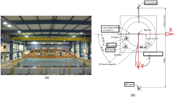
The OCEANIDE BGO FIRST test facility (Figure 2a) is an offshore basin located at La Seyne Sur Mer (France). This is an oceanic basin filled with freshwater and presenting large dimensions (40 m of length, 16 m of width, with an adjustable depth from 0 and 4.8 and a specific pit with a 5 m diameter and 10 m depth). This basin allows the generation of regular and irregular waves up to 0.8 m with a period between 0.6 s and 4s. The water current can be up to 0.4 m/s for 3 m depth and velocity can also be increased by reducing the water depth and/or by adding a convergent. In addition, this facility is able to generate constant squalls or wind up to 5 m/s. The underwater gas blowout was simulated with an air compressor connected to an injection pipe with a 6 mm nozzle and a 10 mm internal diameter. Gas injection was located at a depth of 2.5 m in order to compare the results with those of the experiments performed at CEDRE in the same conditions. To measure the water elevation at the sea surface, 8 resistive probes were used at different positions at the sea surface (Figure 3). In addition to these resistive probes, other measurement devices were used: a high definition video
camera, located at the water surface (HS CAM 1 on Figure 2b), to characterize the fountain shape, a high speed video camera, set in the water column, to measure bubble shape (HS CAM 2 on Figure 2b). A current meter was also used to measure water surface current velocities due to entrained water (1D propeller on Figure 2b). Different flow rates were manually adjusted from 7.8 10-4 Nm3.s-1 to 1.06 10-2 Nm3.s-1 (respectively
25 L.min-1 to 636 L.min-1).
(a)
(b)
Figure 2: (a) Illustration of the experimental OCEANIDE BGO FIRST test facility, (b) location of the different measurement devices
Figure 3: Illustration of the location of the 8 resistive probes used to measure the water elevation
2.2 Cedre experimental setup
The Cedre outdoor basin is an experimental test facility mainly used to deploy and test response means for marine pollution and to run training courses. This basin extends over 1900 m² with a depth of 2.5 m and is filled with seawater with a salinity of 21 psu (Practical Salinity Units). To perform the tests, a floating cell was deployed in the middle of the basin to which the sensors were attached, intended to prevent boundary effects. A 10 mm internal diameter nozzle was located at the center of the floating structure at a depth of 2.5 m. Three different gases were used to study the gas fate at the water surface: compressed air, CO2 and methane. Air
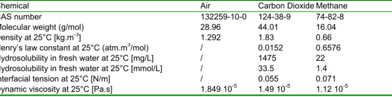
was used as non-hazardous and low-solubility calibration gas. The results were compared to those obtained during the Oceanide experimental campaign. Carbon dioxide was used as a soluble gas and methane, which is a major component of natural gas, was used as slightly soluble product. The physico-chemical properties of air, CO2 and methane are listed in Table 1 for atmospheric pressure and ambient temperature. The water
elevation was measured with 7 handmade capacitive sensors connected to an electronic module which make the probe capacity conversion into height level. Sensors were located in the same configuration as for the Oceanide tests (Figure 3). A 3D acoustic velocimeter (Vector – Nortek) was immerged 15 cm below the sea surface and at 1m away from the center of fountain effect to measure the horizontal surface current average
velocity. This measurement device uses the Doppler effect to measure current velocity by transmitting short pairs of sound pulses, listening to their echoes and measuring the change in pitch or frequency of the returned sound. A Brooks Instrument SLA5853 Series gas mass flow regulator was used to measure and control the gas mass flow rate during the test. Different flow rates were manually adjusted from 4.17 10-4 Nm3.s-1 to 7.5
10-3 Nm3.s-1 (respectively 25 L.min-1 to 450 L.min-1). To control the release conditions, temperature and
pressure were respectively measured inside the injection pipe before the flow regulator. Temperature was measured with thermocouple K while pressure was measured with an industrial transducer with a range between 0-40 bar with an accuracy of 5% of full scale. The mass flow measurements corresponding to normal value (Patm, 0°C). The whole of the experimental set-up is detailed in Aprin et al., 2019.
Table 1: Fluid physical properties for air, CO2 and methane at atmospheric pressure and ambient temperature
(NIST Webbook of physical properties of fluid systems)
Chemical Air Carbon Dioxide Methane
CAS number 132259-10-0 124-38-9 74-82-8
Molecular weight (g/mol) 28.96 44.01 16.04 Density at 25°C [kg.m-3] 1.292 1.83 0.66
Henry’s law constant at 25°C (atm.m3/mol) / 0.0152 0.6576
Hydrosolubility in fresh water at 25°C [mg/L] / 1475 22 Hydrosolubility in fresh water at 25°C [mmol/L] / 33.5 1.4 Interfacial tension at 25°C [N/m] / 0.055 0.071 Dynamic viscosity at 25°C [Pa.s] 1.849 10-5 1.49 10-5 1.12 10-5
3. Results analysis
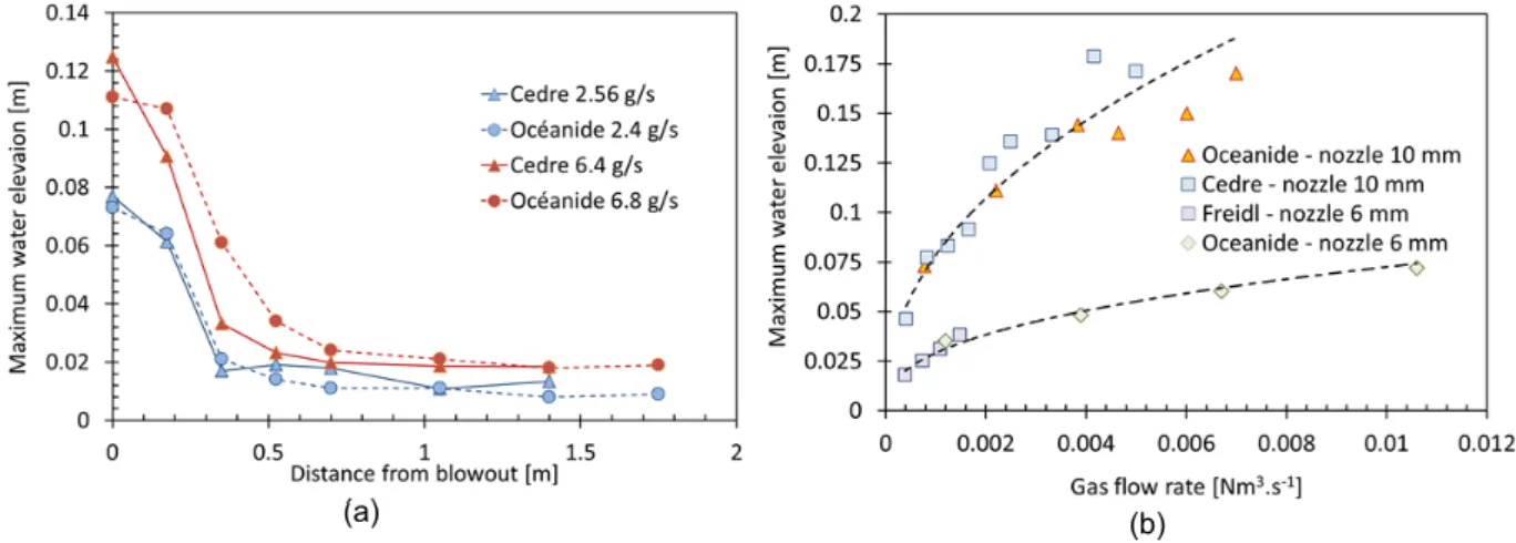
When the gas plume reaches the surface, a boiling zone occurs with a fountain effect which causes an increase in the water height and a strong radial flow is formed at the surface due to the interaction between the plume gas and the surface. This phenomenon is illustrated in Figure 4a which presents the variation of water elevation obtained with air injection and a 10 mm diameter nozzle for the tests carried out with the Oceanide and Cedre experimental setup. Each curve represents the water level measured by resistive probes (for Oceanide setup) and capacitive probes (for Cedre setup) for two different mass flow rates. It clearly shows the fountain effect vertically from the injection point and it can be noted that for similar mass flow rates, the water elevation is quite similar between tests. The difference between values can be explained by the difference between environmental conditions: the Oceanide tests were performed indoors without weather effects while the Cedre tests were carried out outside with wind impact on the blowout. This fountain effect is a boiling zone at the water surface which causes strong radial currents and can cause stability problems for floating structures as indicated in the literature (Engebretsen et al. 1997). As observed in Figure 4a, water elevation is clearly influenced by gas flow rate. Figure 4b presents a comparison of the maximum water elevation for different gas flow rates and two different nozzle diameters. The data were also compared with results obtained by Friedl (Freidl, 1998), who performed tests with compressed air injected into a water tank with a 6 mm injection nozzle. Figure 6b clearly shows the increase in water elevation with gas flow rate and nozzle diameter.
Figure 5a presents the comparison of the maximum water elevation with regard to gas mass flow rate for the three different fluids tested. These results were presented in Aprin et al. (2019) and clearly show that for a given mass flow rate, the maximum water elevation obtained with methane is higher than the air data which are in turn higher than those obtained for CO2. These remarks can be easily explained by the difference in
fluid density. The density of methane is lower than that of air and CO2, so for a given mass released in water,
the methane volume will be two times larger than for air and approximatively three times larger than for CO2.
This volume of gas being larger, the momentum will be greater and the elevation of the water at the surface will necessarily be higher. Thus the consequences of the fountain effect at the water surface will be greater in the case of a methane release because the gas plume will entail a greater amount of water causing faster radial flows at the surface which can cause devastating impacts on structures. Figure 5b is another representation of water elevation versus gas volume flow rate. It can be noted that for the same volume of released gas, the height of the fountain is the same for air and methane. This is consistent because these gases are have low solubility in water. On the other hand, the curve obtained with carbon dioxide is lower than the other two curves for all volume flow rates. This clearly reflects the greater solubility of carbon dioxide in water which involves a reduced volume of gas raising the water surface and therefore less momentum and a lower water elevation.
(a) (b)
Figure 4: (a) Comparison of maximum water elevation measured with resistive and capacitive probes for compressed air tests and 10 mm diameter nozzle for two different mass flow rates. (b) Comparison of the maximum water elevation with regard to gas flow rate for two different nozzle diameters.
(a) (b)
Figure 5: Comparison of the maximum water elevation for the tested fluids (air, carbon dioxide and methane) versus (a) mass gas flow rate (Aprin et al., 2019) and (b) volume gas flow rate.
4. Conclusions
This paper presents the results obtained during experimental tests simulating underwater gas leaks carried out in the test basins of two research labs, Oceanide and Cedre. These tests were carried out to assess the consequences of submarine gas discharges, in particular in the case of an underwater pipeline incident with methane. In this work, we aim at assessing the fountain effect consequences in the case of underwater pipeline leakage. In particular, we measured the maximum water elevation at the sea surface, investigating the effect of injection diameter, gaseous mass flow rate, gas density and solubility in water. The results clearly show that the maximum elevation of water at the surface is strongly dependent on the diameter of the nozzle and the gas flow rate. The comparison of the results between the fluids shows that for the same volume flow of released gas, the fountain effect is substantially identical for methane and air. On the other hand, in the case of a carbon dioxide release, the rise in the water level is lower and is due to the higher solubilisation rate of CO2. This is mainly due to the fact that carbon dioxide is strongly dissolved in water, hence the amount of
gas raising the surface is lower and therefore the amount of movement is less at the surface. The prospects for this work will now consist in comparing the results obtained with simulation tools (CFD or other numerical tools) with the aim of better dimensioning the consequences of blowout type incidents for risk management plans.
Acknowledgments
The present work was carried out within the scope of the program “BLOWOUT” which is funded by the CITEPH program, and particularly supported by TOTAL E&P Recherche Developpement, DORIS Engineering, SUBSEA 7 and Technip. The support of all the sponsors is gratefully acknowledged.
References
Eastwood, C.D., Armi, L., Lasheras, J.C., 2004. The breakup of immiscible fluids in turbulent flows. J. Fluid Mech. 502, 309–333.
Engebretsen, T., Northug, T., Sjøen, K., Fanneløp,T.K., 1997, Surface flow and gas dispersion from a subsea release of natural gas, January, The Seventh International Offshore and Polar Engineering Conference. International Society of Offshore and Polar Engineers
Fingas M., 2017, Deepwater Horizon Well Blowout Mass Balance, Chp. 15, Ed. Mervin Fingas, Oil Spill Science and Technology (Second Edition), Gulf Professional Publishing, 2017, Pages 805-849, ISBN 9780128094136, https://doi.org/10.1016/B978-0-12-809413-6.00015-1.
French-McCay, D.P., Horn, M., Li, Z., Jayko, K., Spaulding, M.L., Crowley, D., Mendelsohn, D., 2018, Chapter 31 - Modeling Distribution, Fate, and Concentrations of Deepwater Horizon Oil in Subsurface Waters of the Gulf of Mexico, Oil Spill Environmental Forensics Case Studies 2018, 683-735, https://doi.org/10.1016/B978-0-12-804434-6.00031-8
Friedl MJ., 1998, Bubble plumes and their interactions with the water surface: Experimental data. Bericht aus dem Institut für Fluiddynamik IFD-IB 98-05, ETH-Zürich, December 1998.
Friedl M.J., Fannelop T.K., Bubbles Plumes and Their Interactions with the Water Surface, Applied Ocean Research vol. 22 (2000), p 119-128.
Grace, J.R., Wairegi, T., Brophy, J., 1978. Break-up of drops and bubbles in stagnant media. Can. J. Chem. Eng. 56 (1), 3–8. http://dx.doi.org/10.1002/cjce.5450560101.
Hinze, J.O., 1955. Fundamentals of the hydrodynamic mechanism of splitting in dispersion processes. Aiche J. 1 (3), 289–295.http://dx.doi.org/10.1002/aic.690010303.
Holand P., 1983, Offshore blowouts, causes and trends. Dissertation, The Norwegian Institute of Technology, Trondheim .
Johansen, O., Rye, H., Cooper, C., 2003. DeepSpill-—Field study of a simulated oil and gas blowout in deep water. Spill Sci. Technol. Bull. 8, 433–443.http://dx.doi.org/10.1016/S1353-2561(02)00123-8.
Martinez-Bazan, C., Montanes, J.L., Lasheras, J.C., 1999. On the breakup of an air bubble injected into a fully developed turbulent flow. Part 1. Breakup frequency. J. Fluid Mech. 401, 157–182. http://dx.doi.org/10.1017/S0022112099006680
Pereira R., Morgado C., Santos I., Rodrigues Carvalho P.V., 2015, Stamp analysis of deepwater blowout accident, Chemical Engineering Transactions, 43, 2305-2310 DOI: 10.3303/CET1543385
Schneider von Deimling, J. ,Linke, P., Schmidt, M., Rehder, G., 2015, Ongoing methane discharge at well site 22/4b (North Sea) and discovery of a spiral vortex bubble plume motion, Marine and Petroleum Geology 68 (2015) 718–730
Solsvik, J., Maass, S., Jakobsen, H.A., 2016. Definition of the single drop breakup event. Ind. Eng. Chem. Res. 55 (10), 2872–2882
Thibaut E., Napoli A., Guarnieri F., 2016, A thorough analysis of the engineering solutions deployed to stop the oil spill following the Deepwater Horizon disaster, Chemical Engineering Transactions, 48, 775-780 DOI:10.3303/CET1648130

![[PDF] Cours Pratique Excel en Pdf | Télécharger PDF](data:image/gif;base64,R0lGODlhAQABAIAAAP///wAAACH5BAEAAAAALAAAAAABAAEAAAICRAEAOw==)