Technology researchers and makes it freely available over the web where possible.
This is an author-deposited version published in: https://sam.ensam.eu Handle ID: .http://hdl.handle.net/10985/8770
To cite this version :
Laurent LANGLOIS, Sandra ZIMMER-CHEVRET, Amarilys BEN ATTAR, Nejah JEMAL, Jonathan HATSCH, Gabriel ABBA, Régis BIGOT - Robotized FSW – Evolution of forces and torque with nonlinear welds - In: 10th International Friction Stir Welding Symposium, China, 2014-05-19 - Proceedings of the 10th IFSWS' 2014 - 2014
Any correspondence concerning this service should be sent to the repository Administrator : [email protected]
10th International Friction Stir Welding Symposium – 19th - 23rd May 2014, China – 1
Robotized FSW – Evolution of forces and torque with
nonlinear welds
L. LANGLOISa, S. ZIMMER (CHEVRET)a, A. BEN ATTARb, N. JEMALb, J. HATSCHb G. ABBAc, R. BIGOTa
a. ARTS ET METIERS ParisTech Metz, Laboratoire de Conception Fabrication Commande, 4 rue Augustin Fresnel, 57078 Metz Cedex 03
b. Institut de Soudure, Centre FSW, 2-4 rue Pilâtre de Rozier, 57420 Goin c. ENIM, Route Ars Laquenexy, 57070 Metz
K
EYW
ORDS:
FSW, Robotization, Forces evolution, complex geometryA
BSTRACTThe main purpose of the article is to study the evolution of the welding forces and torque with non-straight welding path. The main studies performed on forces and torque are usually done on plane straight welding path when the processing parameter are developed. As industrializing robotized FSW, the robot structure deformation under FSW load depends on the forces generated on the tool. Thus, in order to compensate the robot deformation automatically through the control, statistical model giving the welding forces and torque as function of the process parameters is established. This article deals with the study of the forces and torque generated as welding circular and semi-circular welds. The effect of the welding direction (i.e. position of advancing and retreating side) is also analyzed. The objective is to determine if the statistical model giving the welding forces and torque as function of the process parameters developed on straight line can be applied for welding different weld path geometries.
I
NTRODUCTIONFriction Stir Welding (FSW) is an innovative solid state welding process used in many industrial sectors. Its particularity allows the availability to weld all types of aluminum alloys, even the one classified as non-weldable by fusion welding due to hot cracking. It also permits to weld dissimilar assembly like aluminum with steel and weld complex geometry. The robotization of the process allows combining the advantages of FSW with the possibility to perform complex trajectories.
Many experimental research works have been done on this innovative welding process. To realize a sound weld (without internal defect) it is necessary:
to apply the correct processing parameters to keep the tool centered on the seam
to maintain the tool with a certain orientation regarding the workpieces geometries.
However, robots structure possesses a lack of stiffness regarding the high process forces generated during FSW. These deformations are mainly due to the rotational stiffness of the robot articulation (about 75%) and lead to weld defects [SOR10, VOE07]:
10th International Friction Stir Welding Symposium – 19th - 23rd May 2014, China – 2 deviations of the tool position from the seam,
a tool misorientation according to its nominal position defined by the tool technology and the surface geometry to be welded.
The welding consequences are weld defect like lack of penetration. It can also lead to abort the welding operation especially when the tool angle deviation is important [SOR10, VOE07, ZAE10, ZIM14]. Therefore in order to achieve sound weld, it is necessary to compensate the deviation of the tool by taking into account the deformation of the robot due to the welding forces. For given geometry and material of the part to be welded and for a given tool, the welding forces can be characterized as a function of the process parameters (tilt angle, forging force, travel speed and spindle rotation speed). The goal of our research project is to understand and compensate the robot deformations in order to realize FSW of complex shapes with a robot without any defect [QIN13]. Indeed from experimental testing performed on straight weld seam a statistical model giving the welding forces and torque as a function of the process parameters was established [ALL12]. When the prediction of the mechanical interactions between the tool and the material welded is accurate enough, the control of the robot can be integrated in the statistical model. Thus it allows correcting the deviations.
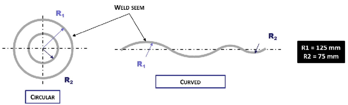
However the statistical models are valid for welds performed with constant process parameters and for straight seam. Therefore this work is dedicated to the study of the welding forces during non-linear weld and its comparison with welding forces involved during straight welds realization. The case study corresponds to butt weld of two 6 mm thick 6082-T651 aluminum sheets. In a first approach only plane circular welds are studied. A parametric experimental plan is carried out; the parameters of the experiments are the curvature of the weld seam and the position of the advancing side according to this curvature. Two kinds of seams are tested, complete circular welds and alternating semi-circular welds as shown in Figure 1. The second seem morphology is chosen in order to reduce the effect of the heating of the parts.
Figure 1: Welded geometries
E
XPERIMENTAL LAYOUTThe tool used is a conventional tool with a concave shoulder of 12 mm diameter and a pin length of 5,8 mm. The machine used is an MTS gantry machine, I-Stir10, from the Institut de Soudure (Figure 2). This type of machine as welding aluminum in this range of thickness can be considered as rigid.
10th International Friction Stir Welding Symposium – 19th - 23rd May 2014, China – 3 This hydraulic machine has sensors inside its head which allows determining the forces applied by the tool during welding. The torque, due to rotational resistance, is also monitored.
Figure 2: MTS I-STIR 10 from the Institut de Soudure, used for all the trials
Circular seam corresponds to a welded geometry performed industrially. As a closed trajectory, the end of the weld corresponds to the starting point. Thus the thermal conditions are not the same all along the welding operation. Two different radiuses are tested (Figure 3) 125 mm and 75 mm.
Figure 3: Circular welds, experimental layout
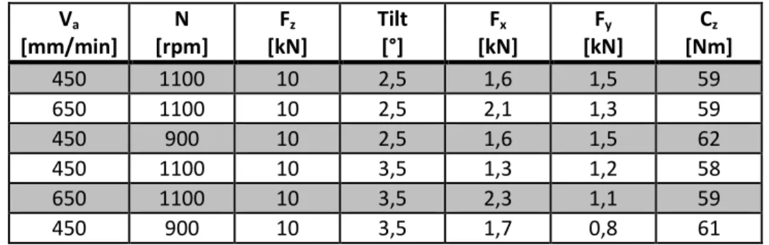
Processing parameters belongings to the process windows (sound welds) for the straight line configuration are selected for the study and are presented in Table 1.
Table 1: Processing parameters used in this study
Pitch
tangage
Roll
roulis
outil
Trial Va [mm/min] N [rpm] Fz [kN] Tilt [°] C1-1 450 1100 10 2,5 C3-1 650 1100 10 2,5 C4-1 450 900 10 2,5 C5-1 450 1100 10 3,5 C7-1 650 1100 10 3,5 C8-1 450 900 10 3,510th International Friction Stir Welding Symposium – 19th - 23rd May 2014, China – 4 Moreover, two welding direction are given (clockwise or counterclockwise). The tool rotation speed direction does not change but the position of advancing and retreating side is changing. This change is represented with the δ parameter defined as:
⃗⃗ ⃗⃗⃗
‖ ⃗⃗ ⃗⃗⃗ ‖ (1)
With :
, the tool rotation speed , the tool angular velocity
, factor determining the position of advancing and retreating side
As =1 advancing side is outside the circle. In this case, the tool rotational frequency according to the workpieces material is the sum of the tool path velocity speed () and the tool rotational speed ():
For=1 : tool/workpiece material = of the velocity = (tool rotation speed + tool path velocity) (2)
As =-1, the advancing side is located inside the circle and the tool angular velocity is subtracted to the tool rotational frequency. So it can be defined:
For=-1 : tool/material = of the velocity = (tool rotation - tool path) (3)
The experimental procedure is composed of the processing parameters given in Table 1, by changing the position of advancing and retreating side and the order of realization of the circle.
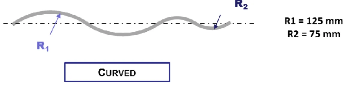
In order to avoid in the results the thermal influence due to excessive heating the circle curved trajectory is also tested. In this configuration presented on Figure 4 heat source is moving along the plate and is not coming back anymore to the weld starting point.
Figure 4: Curved welding path
Almost all of the trials are performed three times and the mean values of the forces are analyzed. Following this paragraph, the results are presented.
R
ESULTSForce evolution as welding Straight line trajectory
The Table 2 presents the forces and torques mean values recorded as welding a straight line. By looking at the evolution of the forces and torques according to the processing parameters, it could notice that:
The torque evolution mainly depends on the rotational speed, The travel force (Fx) evolution mainly depends on the welding speed,
10th International Friction Stir Welding Symposium – 19th - 23rd May 2014, China – 5 Increase of tilt angle is associated with a decrease of the transverse force (Fy),
Passing from 2.5° to 3.5° seems not to significantly influence the travel force amplitude (Fx).
This behavior has also been noticed in the literature by other works [ZIM09, JEM11, PEE06] Va [mm/min] N [rpm] Fz [kN] Tilt [°] Fx [kN] Fy [kN] Cz [Nm] 450 1100 10 2,5 1,6 1,5 59 650 1100 10 2,5 2,1 1,3 59 450 900 10 2,5 1,6 1,5 62 450 1100 10 3,5 1,3 1,2 58 650 1100 10 3,5 2,3 1,1 59 450 900 10 3,5 1,7 0,8 61
Table 2: Forces and torques recorded for the different processing parameters on straight line
Therefore the recorded behavior is as expected. The goal of this work is to study the influence of the forces and torque according to the welded geometry.
Force evolution as welding circular trajectory
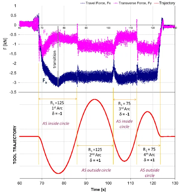
By modifying the processing parameters, changing the welding direction and the order of performing the circle, eight different configurations of trials have been performed. Almost all of them were duplicated three times. The Figure 5 presents the forces recorded as welding first the circle of 125 mm radius and then the one of 75 mm radius. Both circles are performed on the same plate. The forces are analyzed during the stationary stage only. The transition phases like the penetration phase and the acceleration stage are not studied.
By looking at the travel force, a small decrease of travel force (Fx) amplitude can be observed for
10th International Friction Stir Welding Symposium – 19th - 23rd May 2014, China – 6
Figure 5: Forces recorded as welding first the circle of diameter 125mm and then the one of 75mm
On Figure 6 it can be notice that for performing the small circle (75 mm radius) the travel force decreases and the transverse force increases slightly. By looking at the norm of the force Fx and Fy, it
is also noticed a decrease as performing the small circle. By looking at the force amplitude as welding only one circle, the same conclusion could be done. In these results the initial temperature as performing the second circle in the same plate has certainly a small influence. However as welding in different configuration it could be concluded that the diameter to be welded has an influence on the force amplitude. By comparing the force amplitude between the circle and the straight line, an evolution can be noticed. Therefore, the geometry to be welded has an influence of the transverse and travel forces.
10th International Friction Stir Welding Symposium – 19th - 23rd May 2014, China – 7
Figure 6: Travel force evolution according to the circle diameter welded
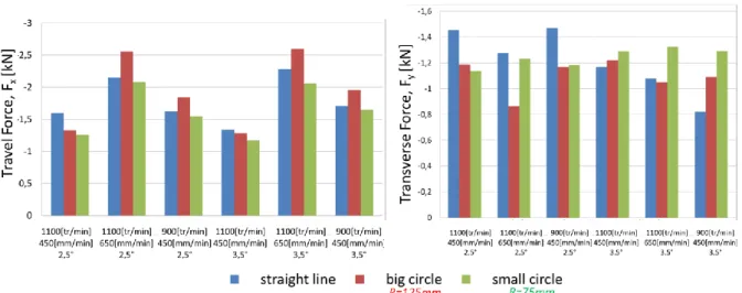
Then, the influence of the position of retreating and advancing side is studied. The Figure 7 presents the Fx and Fy mean values recorded as welding with the advancing side outside the circle (=+1) or
with the advancing side inside the circle (=-1). A slight decrease, but not significant, is observed on the travel force as welding with the advancing side outside the circle. However, by looking at the transverse force, a significant increase can be seen as welding with the advancing side positioned outside the circle. By changing the advancing and retreating side position and keeping the same welding configuration the flow direction around the pin changes. This could explain the change of transverse force measured.
Figure 7: A -Travel force evolution according to the circle welding direction. B - Transverse force evolution according to the circle welding direction
So, these results show that the forces Fx and Fy have some evolutions as welding 2-Dimensional
nonlinear welds. Moreover, the geometry to be welded, in this case the circle diameter and the position of advancing and retreating side seems to have significant importance. The study results show that the position of advancing and retreating side seems to have a greater influence on the forces than the radius to be welded.
In order to avoid any results perturbation due to heat generation, additional tests were done. The welding of curved welding path is performed (Figure 4).
10th International Friction Stir Welding Symposium – 19th - 23rd May 2014, China – 8 Force evolution as welding curved welding path
The Figure 8 presents the travel and transverse force evolution for a curved welding path. After, the transition between the plunge and welding stages, a transverse force evolution can be observed each time the position of advancing side changes its location, inside or outside the circle. The results are the same as the one observed in all the trails done, even if the diameter to be welded is changed. No major differences have been measured for the lateral force as welding this type of geometries. The same transverse force behavior is observed as welding the complete circle, therefore the origin of the phenomena could not be attributed to an excess of heat. So, the location of the advancing and retreating side according to geometry to be welded has an influence on the force amplitude.
10th International Friction Stir Welding Symposium – 19th - 23rd May 2014, China – 9
C
ONCLUSIONThis study has analyzed the influence of the geometry to be welded on generated forces and torque. Previous studies have shown that the travel and transverse forces are depending on the processing parameters. The presented results showed that their amplitude do not only depend on the processing parameters but also depend on the geometry to be welded.
This study showed that as welding circular trajectories (open and closed) the radius to be welded has a small influence on the travel force but the main factor seems to be the position of advancing and retreating side. Indeed the position of advancing and retreating side according to the geometry to be welded is defined by the tool rotational and the welding directions. The position of advancing and retreating side, as welding some circular curvature, has a major influence on the amplitude of the transverse force. This force, as welding with a robot, contributes to tool offset from its initial trajectory. This could generate some defect in the weld.
The torque analysis showed no difference as welding in a straight and in a circular path trajectory. In general, forces measured in a straight and in a circular path trajectory know some difference for both, travel and transverse force. Finally other parameters than processing parameters have an influence in the tool position and misorientation. These parameters have to be taken into account in the statistical model giving the welding forces and torque in order to perform correction deflection with nonlinear welds.
R
EFERENCES[ALL12] ALLAM, Zakaria ; ZIMMER, Sandra ; LANGLOIS, Laurent ; ABBA, Gabriel ; BIGOT, Régis. "Tool workpiece mechanical interaction in FSW", FSWP 2012, Saint-Etienne, France, 2012
[QIN13] Qin, J. Commande hybride position/force robuste d’un robot manipulateur utilisé en usinage et/ou en soudage, PhD Thesis Ecole Nationale Supérieure des Arts et Métiers, France, 2013
[SOR10] M. Soron, J. De Backer, A. K. Christiansson, T. Ilar, Local Model for Online Path Corrections in Friction Stir Welding, 8 th Friction Stir Welding and Processing conference in Lille, France, February 2010
[VOE07] G. Voellner, F. Zaeh, J. Silvanus, O. Kellenberger, Robotic Friction Stir Welding, AeroTech Congress & Exhibition, Los Angeles, California, 2007
[JEM11] N. Jemal, Qualification du domaine de soudabilité en soudage par friction malaxage, PhD Thesis Ecole Nationale Supérieure des Arts et Métiers, France, 2011
[PEE06] M.J. Peel, A. Steuwer, P.J. Withers, T. Dickerson, Q. Shi, H. Shercliff, 2006, Dissimilar Friction Stir Welds in AA5083-AA6082. Part I: Process Parameter Effects on Thermal History and Weld Properties, Metallurgical and materials transactions, Volume 37 A, July 2006-2183
[ZAE10] M. F. Zaeh, G. Voellner Three-dimensional friction stir welding using a high payload industrial robot, Production Engineering May 2010, Volume 4, Issue 2-3, pp 127-133, 2010
[ZIM09] Zimmer, S., Contribution à l’Industrialisation du procédé FSW, PhD Thesis Ecole Nationale Supérieure des Arts et Métiers, France, 20119
[ZIM14] S. Zimmer-Chevret,N. Jemal, L. Langlois, A. Ben Attar, J. Hatsch, G. Abba, R. Bigot FSW Process Tolerance According to the Position and Orientation of the Tool: Requirement for the Means of Production Design, Materials Science Forum Vols. 783-786 (2014) pp 1820-1825, 2014