Science Arts & Métiers (SAM)
is an open access repository that collects the work of Arts et Métiers Institute of Technology researchers and makes it freely available over the web where possible.
This is an author-deposited version published in: https://sam.ensam.eu Handle ID: .http://hdl.handle.net/10985/10089
To cite this version :
Kheireddine BOUZID, Nasser Eddine BELIARDOUH, Corinne NOUVEAU - Wear and Corrosion Resistance of CrN-based Coatings Deposited by R.F Magnetron Sputtering - Tribology in Industry - Vol. 37, n°1, p.60-65 - 2015
Any correspondence concerning this service should be sent to the repository Administrator : archiveouverte@ensam.eu
Wear and Corrosion Resistance of CrN-based
Coatings Deposited by R.F Magnetron Sputtering
K. Bouzid
a, N.E. Beliardouh
b, C. Nouveau
caLaboratoire de métallurgie et génie des matériaux, Université BADJI Mokhtar, BP12, Annaba, 23000 Algeria, bLaboratoire d’Ingénierie des Surfaces, Université BADJI Mokhtar, BP12, Annaba, 23000 Algeria,
cArts et Métiers ParisTech, Laboratoire Bourguignon des Matériaux et Procédés Rue Porte de Paris, 71250, Cluny, France.
Keywords: PVD Wear Corrosion CrN A B S T R A C T
A comparative study was conducted to evaluate the performances against wear and corrosion of CrN, CrMoN, CrZrN, CrVN single layer thin films. The latest are synthesized onto steel substrates (DIN 90CrMoV8), using R.F reactive magnetron co-sputtering. The experimental work was achieved using ball-on-disc configuration in dry conditions against WC balls. The main conclusions are: (i) electrochemical tests in 0.3 wt.% NaCl solution indicated that CrZrN are improved anticorrosion performance when compared to CrN, while CrMoN demonstrated a poor corrosion resistance;(ii) the CrN coating presents the better tribological properties when compared to the ternary nitride coatings.
© 2015 Published by Faculty of Engineering
Corresponding author: Nasser Eddine Beliardouh
Université BADJI Mokhtar, BP 12, Annaba, 23000 Algeria.
Email: beliardouh_23@yahoo.fr
1. INTRODUCTION
The first generation of single layered CrN coatings (cubic CrN and hexagonal Cr2N) has been used as a
protective coating material, because of its has a good wear resistance. In order to improve these properties of CrN coatings, alloying with another metal to form a ternary hard (Al, Si, V…) coating has been explored by many researchers [1-3]. Besides the essential wear resistance requirements, it is additionally desirable that the coating should provide substrate with an improved corrosion resistance especially against Cl- (maritime environment). The paper presents
the analysis of the corrosion and wears resistance performance of a single-layer of CrN coating deposited by reactive electron beam PVD.
2. EXPERIMENTAL PROCEDURE
2.1 Coating deposition and characterization
The CrN and CrXN (X=V, Zr, Mo) coatings are prepared using a RF dual magnetron sputtering system (NORDIKO 3500-13.56 MHz). The target voltages were varied to change the sputtering rate and to modify the composition of the CrXN layers. Chromium and the second metallic targets are co-sputtered at an optimized sputtering rate to yield a uniform 0,7-0,8 µm thick films of desired composition as presented in Table 1.
The substrates were 90CrMoV8 steel samples (La Forézienne-MFLS; France trademark) frequently used to fabricate tools for wood machining. The Chemical composition of the 90CrMoV8 steel was
as follow (wt.%) : C: 0.5 , Mn: 0.5 , Si: 1.0 , Cr: 8, Mo : 1.5, V: 0,5 and Fe: Balance. The parameters of synthesized coatings and more details are given in previous works. [4-5].
Table 1. Chemical composition of synthesized
coatings (atoms %). Coat. Elements Cr O N Mo V Zr CrN 85.2 0.9 13.8 / / / CrMoN 55.4 4.1 18.9 21.6 / / CrVN 60.3 7.4 17.8 / 14.5 / CrZrN 66 5.6 21.3 / / 7.1 2.2 Electrochemical tests
All the electrochemical tests are performed in 0,3 wt.% NaCl solution under free air condition at room temperature (~25 °C). A three electrodes potentiodynamic regime mode was used with a saturated calomel reference electrode (SCE). With simultaneous open circuit potential (OCP) measurement, samples are immersed in the electrolyte as the working electrode for 120 min, respectively to establish the steady state potential. In the following EIS measurement, a sinusoidal AC perturbation of 10 mV amplitude (rms) was applied to the electrode at its corrosion potential (Ecorr). The
impedance data is collected within a frequency range of 0,01 Hz to 103 kHz. The data is
interpreted on the basis of an equivalent circuit through fitting by Zview program.
2.3 Tribological tests
Wear properties of the coatings are evaluated under dry sliding condition at room temperature using a CSM pin-on-disc tribometer (CSM HT 1100), and Tribox 4.1.1 software. The coated disc samples are tested against a WC-6 % Co ball with diameter of 6 mm, surface roughness Ra of
388,57 nm and hardness of 15 GPa. The applied load was 2 N at constant sliding speed of 2 cm/s, and a total sliding distance of 200 m.
3. RESULTS AND DISCUSSION
3.1 Potentiodynamic polarization tests
The Tafel polarization curves, shown in Fig. 1 allow finding the values of anodic and cathodic
slopes, required to calculate an exact value of corrosion rate (Vcorr) for each sample.
1E-11 1E-10 1E-9 1E-8 1E-7 1E-6 1E-5 -0,4 -0,2 0,0 0,2 0,4 0,6 0,8
E (V/E
CS)
Log i (µA/cm²)
CrN CrMoN CrVN CrZrNFig. 1. Potentiodynamic polarization curves of
different samples tested.
These curves indicate that the best behavior related to the corrosion rate should be presented by the CrZrN samples because they present the lowest values of corrosion current densities (Icorr) as mentioned in Table 2.
Table 2. Summary of potentiodynamic polarization
test results.
Coating Icorr(nA) Ecorr(mV) Vcorr.10-3 (mm/y)
CrN 19,2 -58,5 14,22 CrZrN 10 51,4 13,97 CrMoN 136 -143 169
CrVN 67,1 37 93,82
The decrease in Icorr of films is a great evidence of
the improvement in the corrosion resistance.
3.2 Electrochemical impedance spectroscopy measurements
In order to investigate the corrosion performance of PVD hard coating, it was well-known that EIS has found its efficacy [6]. The different shapes of the curves in Nyquist diagrams are obtained as shown in Figure 2(a). The CrZrN coating presents the best corrosion resistance followed by the (CrVN).The CrMoN presents the lowest corrosion resistance. This result confirms the data obtained by potentiodynamic tests (Table 2). In addition, all of the Nyquist plots show two time constants, with a capacitive loop of smaller diameter followed by another capacitive loop of larger diameter. Bode plots of the phase angle as a function of the frequency shown in Fig. 2(b), confirm that the Nyquist’s data.
Fig. 2 AC impedance measurements of the coated
samples (a) Nyquist impedance diagrams(insert image shows the Nyquist plots at high frequencies), (b) Bode plots and (c) the equivalent circuit model.
From the above mentioned result, it is confirmed that there are effectively two time constants in the experimental frequency bandwidth. Consequently the EIS data indicates the existence of two different interfacial reactions which can be related to the coating/solution interface and substrate/solution interface respectively.
The experimental results are interpreted via developing typical impedance models for electrode surfaces and curve-fitting on the basis of an equivalent circuit using Zview impedance program. A circuit model was proposed to ascribe two sub-electrochemical interfaces generally used in such case [7].
The equivalent circuit (Fig. 2 (c)) consists of the following elements: Rs corresponds to the solution resistance of the electrolyte test between the working electrode (WE), and reference electrode (RE). CPE1 and Rpo elements are used in parallel to replace the coating dielectrics properties. CPE2 and Rct in parallel are adapted to describe charge transfer at the coating/substrate interface. Results of fitting values obtained by equivalent circuit simulation of different coating configurations indicate that the CrZrN coating has lower CPE1 value and higher charge transfer resistance. On the other hand, the total polarization resistance
(Rp) is taken as the sum of all resistances
obtained from EIS results [8].
ct po
p
R
R
R
(1) Rp can be considered to be an indicator of thecorrosion resistance of the material, which is inversely proportional to the corrosion velocity [9]. The Rp of CrZrN was around 48.103 KΩ thus
multiplying by factor 04 (four) the Rp value of CrN (12,15.103 KΩ) indicating their high
corrosion resistance. The Rp values for CrVN and CrMoN are 3. 103 KΩ and 48,23 KΩ,
respectively . These results showed a good agreement with the Tafel potentiodynamic polarization measurements.
3.3 SEM investigations
Significant macro particles, droplets and growth defects, which are formed during sputtering process, can be observed on the surface of the coatings in addition to various pinholes and craters. Figure 3 presents an example of the surface morphology of the CrZrN coating after 24 h of immersion and potentiodynamic test measurements in a 0,3 wt. % NaCl solution. SEM images can prove that selective corrosion occurs at growth defect sites. According to Lewis et al. [10], a droplet is compositionally metal rich and nitrogen deficient; this defect is anodic with respect to both surrounding coating. It is obvious from Fig. 3, that the corrosive attack occurs with the ejection of droplets (insert image A in Fig. 3) from the coatings which creates a crater (insert image B) at its surface, resulting in direct contact with the substrate.
When compared to similar CrN based coatings, as reported in other works [7-9], our study indicates that all of coatings present better behavior against aggressive chloride ions (Cl-). It can be concluded
that the different electrochemical behavior may be associated with their different surface defect densities. Our results confirm the remarkable resistance against corrosion in NaCl solution, of CrZrN obtained by Zhang et al. [11]. The authors conclude that the additions of Zr into CrN coatings improved their chemical inertness and the corrosion mechanism was due to the slight pitting corrosions, which were mainly localized in the growth defects.
Fig. 3. SEM micrographs of CrZrN surface. Corrosion damage after potentiodynamic polarisation test; Insert
images: cross section view (A) showing droplet and crater in (B). 3.4 Friction coefficient and wear rate
The objective of the second part of this work was to analyze the surface states of the coated samples in terms of the friction coefficient (µ) evolution during dry sliding against WC balls. Fig. 4 shows the variation in the friction coefficient as a function of the number of sliding cycles. It can be seen, at the start of test, the CrN curve shows a running-in period, characterized by an initial transient state followed by a sudden friction coefficient increase and a final gradual-steady state about 0,4.
Fig. 4. Coefficient Of Friction evolution vs cycles of
coated samples.
The friction behavior of CrN against WC balls was in agreement with results obtained by other researchers [12-13] although the experimental conditions are not exactly the same.
However, the friction coefficients behavior for ternary CrN-based coatings (CrZrN, CrMoN, and CrVN) in combination with WC balls present similar features: in both cases, the friction coefficient increased rapidly at the start of the test to a maximum value of about 0,85-0,9. Thus, the wear of ternary CrN based coatings was visibly higher than the wear of CrN.
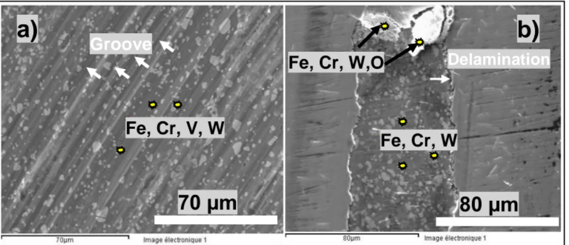
3.5 SEM Analysis of wear tracks
Figure 5 shows the wear scar of CrN and CrVN coatings as an example of SEM observations. The main difference is the fact that plowed grooves along the sliding direction are found on the wear tracks of CrVN, as well as CrMoN and CrZrN as presented in Fig. 5(a).
The wear scar of the tested ternary coatings shows abrasive marks, pits and excess wear debris. Consequently, the three‐body abrasive wear was the dominant wear mechanism as reported by M.S. Priyan et al. [14].
B
1 µm
1
µm
10 µm
A
A
B
Fig. 5. SEM micrographs of wear track observed on (a) CrVN and (b) CrN when sliding against WC balls.
No grooves and no scratches are shown inside the CrN wear scar. EDX analysis of wear tracks of ternary nitride coatings reveals the presence of coating’s elements (Cr, V, Mo, Zr, N), elements of substrate (Fe) and elements of the counter-part (W). The presence of tungsten is a sign of an adhesive wear. On another hand, absence of oxygen (O) indicates that the wear track is free of oxide. Consequently, the wear mechanism of the ternary coatings seems to be a combination of abrasive and adhesive wear.
In the contrary, SEM investigations of the worn surface of CrN, Figure 5(b), reveal the presence of oxygen (O), in the middle of the wear scar. Consequently the CrN coating suffers a combination of adhesive and delamination wear. It can be noticed that the presence of debris (wear product) inside de wear track can act as a solid lubricant by rolling, and thus reducing the friction. We consider that is the reason why CrN presents lower COF evolution than other ones.
4. CONCLUSION
The following conclusions are deduced from the experimental result:
All of coatings present better behavior against aggressive chloride ions (Cl-).
Electrochemical tests indicated that CrZrN had an improved anticorrosion performance when compared to CrN, while CrMoN demonstrated a poor corrosion resistance. The different electrochemical behaviors are associated with their different surface defect densities.
Tribological tests against WC balls indicate, that CrN coating presents the lowest coefficient of friction relatively to the ternary nitride coatings. Both the CrVN, CrMoN and CrZrN coatings underwent severe wear combinations of abrasive and adhesive wear. The CrN endure a mixture of adhesive, and delamination wear.
Acknowledgments
The authors would like to thank Dr. Aurelien BESNARD, Mr. Denis LAGADRILLERE (LaBoMap, Paristech of Cluny) for experimental support and Professor Sihem ABDERRAHMANE (LIS laboratory) for helpful discussions.
REFERENCES
[1] J. Mo and M. Zhu, 'Sliding tribological behavior of AlCrN coating', Tribology International, vol. 41, no. 12, pp. 1161-1168, 2008.
[2] D. Philippon, V. Godinho, P. Nagy, M.
Delplancke-Ogletree and A. Fernández, 'Endurance of TiAlSiN coatings: Effect of Si and bias on wear and adhesion', Wear, vol. 270, no. 7-8, pp. 541-549, 2011.
[3] K. Bobzin, N. Bagcivan, M. Ewering and R.H.
Brugnara, 'Vanadium Alloyed PVD CrAlN Coatings for Friction Reduction in Metal Forming Applications', Tribology in Industry, vol. 34, no. 2, pp. 101-107, 2012.
[4] Y. Zou, M.J. Walock, S.A. Catledge, C. Nouveau, and A. Stanishevsky, 'Thermal stability and mechanical properties of sputtered Chromium-Molybdenum-Nitride (CrMoN) coatings', J. of
Fe, Cr, W,O
DelaminationFe, Cr, W
Fe, Cr, V, W
Groove
a)
b)
80 µm
70 µm
Achievements in Materials and Manufacturing Engineering, vol.37, no. 2, pp. 369-374, 2009. [5] Y. Benlatreche, C. Nouveau, I. Rahil, R. Marchal
and L. Chekour, 'Comparative Studies on Mo-Cr-N and Al-Cr-Mo-Cr-N Coatings Obtained by PVD Dual Magnetron Sputtering', Plasma Processes Polym., vol. 6, no. 1, pp. S135-S140, 2009.
[6] C. Liu, Q. Bi and A. Matthews, 'EIS comparison on corrosion performance of PVD TiN and CrN coated mild steel in 0.5 N NaCl aqueous solution', Corrosion Science, vol. 43, no. 10, pp. 1953-1961, 2001.
[7] G. Song, X. Yang, G. Xiong, Z. Lou and L. Chen,
'The corrosive behavior of Cr/CrN multilayer coatings with different modulation periods',
Vacuum, vol. 89, pp. 136-141, 2013.
[8] Y. Chipatecua, J. Olaya and D. Arias, 'Corrosion behaviour of CrN/Cr multilayers on stainless steel deposited by unbalanced magnetron sputtering', Vacuum, vol. 86, no. 9, pp. 1393-1401, 2012.
[9] A. Ruden, E. Restrepo-Parra, A. Paladines and F. Sequeda, 'Corrosion resistance of CrN thin films produced by dc magnetron sputtering', Applied
Surface Science, vol. 270, pp. 150-156, 2013.
[10] D. Lewis, S. Creasey, C. Wüstefeld, A. Ehiasarian and P. Hovsepian, 'The role of the growth defects on the corrosion resistance of CrN/NbN superlattice coatings deposited at low temperatures', Thin Solid Films, vol. 503, no. 1-2, pp. 143-148, 2006.
[11] Z. Zhang, O. Rapaud, N. Bonasso, D. Mercs, C. Dong and C. Coddet, 'Microstructures and corrosion behaviors of Zr modified CrN coatings deposited by DC magnetron sputtering', Vacuum, vol. 82, no. 11, pp. 1332-1336, 2008.
[12] J. Lin, W. Sproul and J. Moore, 'Tribological behavior of thick CrN coatings deposited by modulated pulsed power magnetron sputtering',
Surface and Coatings Technology, vol. 206, no.
8-9, pp. 2474-2483, 2012.
[13] L. Shan, Y. Wang, J. Li and J. Chen, 'Effect of N2 flow rate on microstructure and mechanical properties of PVD CrNx coatings for tribological application in seawater', Surface and Coatings
Technology, vol. 242, pp. 74-82, 2014.
[14] MS. Priyan, P. Hariharan, A. Azad and KS. Kumar: 'Microstructure and Wear Analysis of FeBCr Based Coating Deposited by HVOF Method',
Tribology in Industry, vol. 36, no. 2, pp. 134‐143,