Machinability of Stainless Steel Alloys
by
Osama ELFASI
THESIS PRESENTED TO ÉCOLE DE TECHNOLOGIE SUPÉRIEURE
IN PARTIAL FULFILLMENT FOR A MASTER’S DEGREE WITH THESIS
IN MECHANICAL ENGINEERING
M. A. Sc.
MONTREAL, NOVEMBER 30, 2018
ÉCOLE DE TECHNOLOGIE SUPÉRIEURE
UNIVERSITÉ DU QUÉBEC
© Copyright reserved
It is forbidden to reproduce, save or share the content of this document either in whole or in parts. The reader who wishes to print or save this document on any media must first get the permission of the author.
BOARD OF EXAMINERS
THIS THESIS HAS BEEN EVALUATED BY THE FOLLOWING BOARD OF EXAMINERS
Mr. Victor SONGMENE, Thesis Supervisor
Mechanical Engineering Department, École de technologie supérieure
Mr. Anh Dung NGÔ, President of the Board of Examiners
Mechanical Engineering Department, École de technologie supérieure
Mr. Fawzy-Hosny SAMUEL, Member of the jury
Mechanical Engineering Department, , University of Chicoutimi
Mr. Marek BALAZINSKI, External Evaluator
Mechanical Engineering Department, École polytechnique de Montréal
THIS THESIS WAS PRESENTED AND DEFENDED
IN THE PRESENCE OF A BOARD OF EXAMINERS AND PUBLIC
IN NOVEMBER 13, 2018
ACKNOWLEDGMENT
First of all, I would like to express my gratitude to my family and especially to my mother for all she has offered me, and I would like to express my sincere gratitude to my research director, Professor Victor Songmene.
Machinability of Stainless Steel Alloys Osama ELFASI
RESUME
Le présent travail porte sur le fraisage à sec des aciers inoxydables ferritiques AISI 409, austénitiques AISI 304L et martensitiques AISI 410 en mettant l'accent sur l'influence de différents paramètres tels que la vitesse de coupe, la vitesse d'avance et la profondeur de coupe et sur la formation de copeaux. Un grand accent est mis sur les interactions des matériaux avec le processus d'usinage. Pour ces essais d'usinage, les échantillons ont été usinés avec différents paramètres de coupe en utilisant le même outil afin de développer une approche globale permettant de prédire le comportement en usinage (rugosité de surface, forces, bavures et formation de copeaux).
Les résultats ont montré que la rugosité de la surface augmente avec l'augmentation de la vitesse d'avance et de la vitesse de coupe. Il a également été constaté qu'il existe une relation entre la dureté du matériau et la rugosité de la surface. La vitesse de coupe s'est avérée avoir un impact considérable et évident sur la force de coupe. Les différences observées dans la morphologie des copeaux ont été reliées aux différences de dureté des pièces. Moins de bavures ont été observées sur la surface de la pièce à la vitesse de coupe élevée. Il a été constaté que la dureté du matériau et la vitesse de coupe ont un effet considérable sur la formation de bavure. Une augmentation de la vitesse de coupe sur des matériaux plus durs réduit considérablement les bavures et améliore ainsi la qualité de la surface.
Un choix adéquat de la vitesse de coupe et de l'avance par dent ont permis d'obtenir des conditions de coupe favorables avec des forces de coupe stables et modérées, en plus de réduire les vibrations.
Enfin, des corrélations ont été établies entre la rugosité de surface, les forces de coupe et la formation de copeaux. Sur la base d'une analyse statistique prenant en compte les forces de coupe, la dureté de la pièce et les microstructures, une recommandation sur les paramètres de coupe optimaux favorisant l'usinabilité des alliages d'acier inoxydable testés a été formulée.
Mots clés: AISI 409 Ferritique, AISI 304L Austénitique, AISI 410 Martensitique, usinage, Fini de surface, Forces de coupe, Bavure, Formation de copeaux.
Machinability of Stainless Steel Alloys Osama ELFASI
ABSTRACT
The present work investigates dry milling of AISI 409 Ferritic, AISI 304L Austenitic and AISI 410 Martensitic Stainless Steel with focus on the influence of different parameters such as cutting speed, feed rate and depth of cut on the surface roughness, cutting forces, burr formation and chip formation. A great emphasis is put on the materials interactions with the machining process. For these machining tests, specimens were machined under different cutting parameters using the same tool in order to develop a global approach to predict the machining behaviour (surface roughness, forces, burr and chip formation).
The results showed that the surface roughness increases with the increase of the feed rate and the cutting speed. It was also found that there exist a relationship between the material hardness and surface roughness. The cutting speed was found to have a considerable and clear impact on cutting force. Differences observed in chip morphology were linked to the changes in workpiece hardness. Fewer burrs were observed on the workpiece surface at high cutting speed. It has been found that the material hardness and the cutting speed have a considerable effect on the burr generated. An increase in the cutting speed on harder materials reduces considerably burr and thus improve surface quality. An adequate choice of cutting speed and feed per tooth, allows a favourable tool operating condition with stable and moderate cutting forces in addition to reduced vibrations.
Lastly, correlations were established between surface roughness, cutting forces and chip formation. Based on a statistical analysis that takes into account the cutting forces, the workpiece hardness and microstructures, a recommendation on the optimal cutting parameters that favours the machinability of the tested stainless-steel alloys was made.
Keywords: AISI 409 Ferritic, AISI 304L Austenitic, AISI 410 Martensitic, Machining, Surface roughness, Cutting Forces, Burr, and Chip Formation.
TABLE OF CONTENTS
INTRODUCTION ...1
CHAPTER 1 LITERATURE REVIEW ...5
1.1 Introduction ...5
1.2 Importance of Material Removal ...5
1.3 Metal cutting ...5
1.3.1 Milling Operation ... 6
1.3.2 Turning Operations ... 6
1.4 Cutting mechanics ...6
1.4.1 Heat in metal cutting ... 8
1.5 Machinability ...9
1.5.1 Machinability Criteria, Tests, and Indices ... 9
1.5.2 Work piece material properties ... 10
1.5.3 Hardness and Strength ... 10
1.5.4 Ductility ... 11
1.5.5 Effect of deformation and heat treatment processes ... 12
1.5.6 Surface roughness ... 13
1.5.7 Cutting Forces ... 16
1.5.8 The chip formation ... 18
1.5.9 The burr ... 20
1.6 Types of Stainless steels ...21
1.6.1 Ferritic ... 22
1.6.2 Martensitic ... 22
1.6.3 Austenitic ... 22
1.6.4 Duplex ... 22
1.6.5 Machining of stainless steels ... 23
1.6.6 The machinability of stainless steel ... 24
1.7 Tool wear ...26
1.7.1 Load factors ... 26
1.7.2 Tool wear mechanisms ... 28
1.7.3 Types of tool wear ... 29
1.8 The tool life ...34
1.9 Conclusion ...35
CHAPTER 2 METHODOLOGY ...37
2.1 Introduction ...37
2.2 The test materials ...37
2.3 Experimental plan ...41
2.4 Error calculation ...45
2.5.1 Machine tool. ... 46
2.5.2 Microscope ... 47
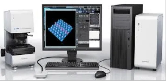
2.5.3 Lext microscope for measuring Microstructure. ... 48
2.5.4 Mitutoyo SJ 410 for measuring Surface Quality ... 49
2.5.5 Dynamometer for force measurement ... 49
2.5.6 Mitutoyo Rockwell hardness testing machine ... 51
CHAPTER 3 RESULTS AND DISCUSSION ...53
3.1 Introduction ...53
3.2 Surface roughness analysis ...54
3.2.1 Statistical analysis ... 54
3.2.2 Analysis of variance (ANOVA) ... 63
3.2.3 Surface quality (µm) ... 71
3.3 Cutting force analysis ...75
3.3.1 Identification of dynamic cutting force: ... 75
3.3.2 The analysis impact of cuttine speed and feed rate on cutting force of 409 Ferritic: ... 76
3.3.3 The analysis impact of cutting speed and feed rate on cutting force of 304L Austenitic:... 78
3.3.4 The analysis impact of cutting speed and feed rate on cutting force of410 Martensitic: ... 80
3.3.5 Comparison between three different alloys on dry milling operation ... 81
3.4 Chip forming analysis ...83
3.4.1The chip forming of stainless steel materials 409 Ferritic ... 83
3.4.1 The chip forming of stainless steel materials 304L Austenitic ... 85
3.4.2 The chip forming of stainless steel materials 410 Martensitic ... 86
3.4.3 The Comparison of chip geometry for three different grades of stainless steel ... 88 3.4.4 The burr:... 89 3.5 Machinability Comparison...91 CONCLUSION ...93 RECOMMENDATIONS ...97 BIBLIOGRAPHY… ...99
LIST OF TABLES
Page
Table 1.1 General impact of increasing values of different properties on machinability ...11
Table 2.1 Hardness of Test Materials ...38
Table 2.2 Chemical composition (weight %) of test materials (as supplied by the manufacturers) ...38
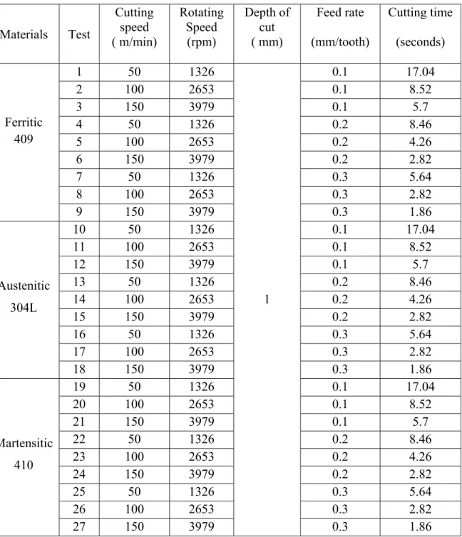
Table 2.3 Experiments parameters data ...41
Table 2.4 The Cutting Data Parameters of the Stainless Steel Alloys ...42
Table 2.5 Tool specifications ...43
Table 2.6 Data of Machine Taken from 2014 Yamazaki ...46
Table 3.1 Data of surface roughness dependence on cutting speed and feed rate for the 409 54 Table 3.2 Data of surface roughness on cutting speed and feed rate for the 304L ...57
Table 3.3 Data of surface roughness on cutting speed and feed rate for the 410 ...59
Table 3.4 Shows cutting tool for experiments 7, 8 and 9 for material 410 shows minimum and maximum tool wear for each tool, and the volume of material removed 1800mm3 ...62
Table 3.5 ANOVA result for Ra (μm) with 95% confidence level ...63
Table 3.6 ANOVA result for Rq (μm) with 95% confidence level ...63
Table 3.7 ANOVA result for Ra (μm) with 95% confidence level ...66
Table 3.8 ANOVA result for Rq (μm) with 95% confidence level ...66
Table 3.9 ANOVA result for R a (μm) with 95% confidence level ...69
Table 3.10 ANOVA result for Rq (μm) with95% confidence level ...69
Table 3.11 Data of average (Ra) and (Rq) of different grades of stainless steels tested ...71
Table 3.12 Cutting force data based on cutting speed and feed rate for 409 Ferritic ...77
Table 3.13 Cutting force data based on cutting speed and feed rate for 304L Austenitic ...78
Table 3.15 Data of arithmetic cutting force of three diverse grades of stainless steel ...82
Table 3.16 Comparison of the chip form for the tests of 409 Ferritic ...84
Table 3.17 Comparison of the chip form for the tests of 304L Austenitic ...85
Table 3.18 Comparison of s the chip form for the tests of 410Martensitic ...87
Table 3.19 Comparison of the from chip geometry for three tests of three materials ...88
Table 3. 20 Comparison of burr formation for the three stainless steel materials tested (feed rate 0.1mm/ tooth) ...90
LIST OF FIGURES
Page
Figure 1.1 Shear plane and chip forming factors ...7
Figure 1.2 Chip contact areas Take from (Black et al., 1996 ...8
Figure 1.3 Heat distribution in metal cutting ...9
Figure 1.4 Diagram change of mechanical properties with carbon content ...10
Figure 1.5: Ductility (D) Hardness (HB) ...11
Figure 1.6 Definition of the arithmetic average height (Ra) ...13
Figure 1.7 The ten-point height parameter (Rz) ...15
Figure 1.8 Definitions of the parameters Rp, Rv, Rt ...15
Figure 1.9 Relationship between cutting force and cutting speed ...16
Figure 1.10 The three components of the cutting force ...17
Figure 1.11 The relationship between cutting force and chip thickness ...17
Figure 1.12 Relationship between cutting force and rake angle ...18
Figure 1.13 The ways to break a chip ...19
Figure 1.14The types of chip formation ...20
Figure 1.15 The burr ...21
Figure 1.16 Typical wear zones ...27
Figure 1.17 Typical wear zones ...27
Figure 1.18 Data of wear mechanisms ...29
Figure 1.19 Places of wear on insert ...29
Figure 1.20 Flank wear ...30
Figure 1.21 Crater wear ...30
Figure 1.23Notch wear on the trailing edge ...31
Figure 1.24 Thermal cracking ...32
Figure 1.25 Mechanical fatigue cracking ...32
Figure 1.26 Chipping of the cutting edge ...33
Figure 1.27 Fracture ...33
Figure 1.28 The built-up edge (BUE) ...34
Figure 2.1 Microstructure of ...39
Figure 2.2 Microstructure of ...40
Figure 2.3 Microstructure of ...40
Figure 2.4: The TOOL ...43
Figure 2.5 The tests layout during experiment ...44
Figure 2.6 Mazatrol MATRIX NEXUS CNC ...47
Figure 2.7 Digital microscope KEYENCE, VHX-500F ...47
Figure 2.8 The LEXT OLS4100 laser scanning digital microscope ...48
Figure 2.9 Mitutoyo measured Surface Quality testing machine ...49
Figure 2.10 Cutting efforts at milling and Kistler 9255B Torque Acquisition System ...50
Figure 2.11 Mitutoyo Rockwell hardness machine ...51
Figure 3.1 Curves showing mean Ra as a function of different speeds and feed of 409 Ferritic ...55
Figure 3.2 Average Ra and Rq of 409 Ferritic...55
Figure 3.3 Curves showing mean Ra as function of different speeds and feed of 304L Austenitic ...57
Figure3.4 Average Ra and Rq of the 304LAustenitic ...58
Figure 3.5 Curves showing mean Ra as the function of different speeds and feed of the 410 Martensitic ...60
Figure 3.7 Main impact plot for Ra (µm) on 409 Ferritic ...64
Figure 3.8 Main impact plot for Rq (µm) ...65
Figure 3.9 Main impact plot for Ra (µm) ...67
Figure 3.10 Main impact plot for Rq (µm) ...68
Figure 3.11 Main impact plot for Ra(µm) ...70
Figure 3.12Main impact plot for Rq(µm) ...71
Figure 3.13 Average Ra and Rq of three different grades of stainless steels ...71
Figure 3.14 Image of tool wear when cutting 410 (50×) Cutting Speed at 150m/min and feed rate at 0.1 mm/tooth ...72
Figure 3.15 Data of profile surface roughness parameters dependence on cutting speed 150m/min and feed rate 0.1mm/tooth, for the 409 Ferritic...73
Figure 3.16 Data of profile surface roughness parameters dependence on cutting speed 150m/min and feed rate 0.1mm/tooth, for the 304L Austenitic ...74
Figure 3.17 Data of profile surface roughness parameters dependence on cutting speed 150m/min and feed rate 0.1mm/tooth, for the 410- Martensitic ...75
Figure 3.18 Cutting force vs Time ...76
Figure 3.19 Curves showing mean cutting force of different cutting speeds and feed rates of the 409 Austenitic ...77
Figure 3.20 Curves showing mean cutting force of different cutting speeds and feed rates of the 304L Austenitic ...79
Figure 3.21Curves showing mean cutting force of different cutting speeds and feed rates the 410 Martensitic ...81
Figure 3.22 Cutting Forces of three different grades of stainless steel ...82
Figure 3.23 comparative machinability related to Surface finish ...91
LIST OF ABREVIATIONS
ANN: Artificial neural network ANOVA: Analysis of variance.
AISI: the American Iron and Steel Institute. BUE: Built-Up Edge.
ISO: International standard organizations. SEM: Scanning electron microscopy. .
LIST OF SYMBOLS
X : Values determined from a series of n measurements ̅: The average value of a series of n measurements n: The total number of measurements
a: Axial depth of cut
dz: Differential height of the chip segment
dFr, dFt, dFa: Differential tangential, radial and axial forces D, R, Rr, R2: Parametric radial dimensions of the end mill Fx, Fy, Fz: Force components in the X, Y and Z directions h: Valid cutting edge height from the tool tip
Ktc, Krc, Kac: Cutting force coefficients in tangential, radial and axial directions Kte, Kre, Kae: Edge force coefficients in tangential, radial and axial directions CI: Clearance angle
ap: Depth of cut
N: Rotational speed(rpm) Vc: Cutting speed (m/min)
Ra: The arithmetic average height Rq: Root mean square roughness Rt: The maximum height of the profile Rz: Ten-point height
INTRODUCTION
Some metals are more difficult to machine, or cut than others. Metal cutting processes involve removing unwanted material from metallic parts with harder shaped tools. These tools plunge into the metal and plastically deform some portion to remove them from the main part. These operations are explained by using basic orthogonal and oblique cutting models (Stephenson et Agapiou, 2005).
In the present study, we experimentally investigate the cutting tool and work material interactions during the machining of hardened materials (stainless steels) used in industry. The materials under consideration are three stainless steel alloys namely; the AISI 409-gradeFerritic stainless steel, the AISI 304L- grade Austenitic stainless steel, and the AISI 410 -grade Martensitic stainless steel, whose features include high mechanical strength and heavy-weight.
These three metal alloys are low alloy stainless steel characterized by high tensile strength and toughness and used in the manufacture of several structural components for the automotive and aerospace industries. These materials were selected in an attempt to provide a comprehensive study of the machining of large range of metals. The next paragraphs will enumerate the steps taken during the investigation.
Firstly, experimental tests will be carried out on a high precision CNC (Computer Numerical Control) machine, under dry milling conditions by varying cutting parameters like cutting velocity, feed rate and the depth of cut. Thereafter, surface quality testers will be used to measure the surface quality of the workpiece. In addition, the digital microscope will also be used to measure chip and chip formation mechanism during the milling process to better understand the chip formation process.
Afterwards, standards will be selected with various criteria aiming at finding the best possible range of values for machining and equipment safety.
Lastly, a three components dynamometer with data acquisition system is used to determine the cutting forces component FY, feed force component FX and radial or thrust force component FZ.
The machinability criterion of materials is usually evaluated using indicators such as surface roughness, chip formation, tool wear, and cutting forces. However tool wear and surface roughness are the most often used. Since the tool wear is not considered in the present work, only surface roughness, chip formation and cutting forces results are considered. Previous research works on the surface roughness of machined stainless steels alloys and hardened stainless steels are also reported in this chapter.
The purposes and objectives of the study
The purpose of this research is to gain a deep understanding of the fundamental machining of stainless steel alloys: The AISI 409-grade Ferritic stainless steels, the AISI 304L- grade Austenitic stainless steels, and the AISI 410 -grade Martensitic stainless steels.
The specific objectives of the study are:
1) To establish and measure the surface roughness after machining the workpieces using calibrated digital microscopes.
2) To determine the cutting forces component FY, feed force component FX and radial or thrust force component FZ by using three components dynamometer with data acquisition system.
3) To construct new cutting force model using particular cutting force in various parameters to gain the best result in milling process in terms of measure, standard, size and impact on tool wear origin and surface quality process.
4) To investigate chip morphology, burr development, and assess the chip formation mechanism during milling to better understand its formation process.
5) To measure the tool wear for each experiment by Optical Microscopy, and study the tool wear improvement and related parameter in order to represent tool wear in various cases. Structure of thesis
The theses consists of four parts: It begins with introduction followed by the first chapter that presents the literature review, the second chapter explaining the methodology the third chapter containing a summary of the results linked to the proposed research goals. In the last chapter, conclusion, recommendation and outline for the future work will be discussed.
The experimental cases and situations with all parameters used in this research project will be given at the beginning of each chapter. A brief discussion on each chapter is structured as following:
Chapter 1: Displays a detailed outline on metal cutting tools and typical cutting operations. Also, types of stainless steels and the machinability of stainless steel are summarized. Tool wear, and types of tool wears are presented. Therefore, this chapter reviews previous research works in areas relevant to the machinability and surface roughness characteristics of machined parts made of stainless steels alloys.
Finally, the tool-life decreasing and removal are reviewed. Specific focus is paid to milling. This chapter furthermore presents a review of burr, the surface roughness, and chip formation. A general review or summary of optimization technique is displayed, after which epilogue of the state of the art literature review is presented.
Chapter 2: Shows and presents a set of experimental works to realize and comprehend the variation condition of the surface integrity. The experimental plan has been prepared according to a factorial design. The experiment of milling tool against austenitic stainless steel dry cutting test will be conducted. The cutting test will be carried out using CNC Milling tool and Mazak (Vertical Center, NEXUS 410A). The work piece will fixed by means of the vice. The radius of the cutting tool is 6 mm. Another objective of the chapter is also to comprehend and realize the formation mechanism and dominant process parameters on visible and big burrs during end milling of three stainless steel alloys (409 Ferritic , 304L Austenitic, and 410Martensitic 410). The factors scrupulous include the cutting tool, the machining parameters, geometry tool, and the workpiece material.
Chapter 3: It consists of an analytical model of the final milling in materials based on of the choice of the geometry of the formation of optimal levels of setting process parameters for the optimization of multiple responses.
Besides, a study of the effects of cutting conditions on surface roughness parameters is presented with a discussion of the results. In addition, an analysis of the impact on chip formation, burr, and cutting force. The recorded optimal cutting parameters were studied to
generate an experimental model that recommends optimal cutting parameters for different tools with a prediction of arithmetic surface roughness value. In addition, we treated the damage or defects that appear on the different functional faces of the cutting tool.
Finally, the conclusion: It consists in presenting the most significant summaries and conclusions of the research work presented in Chapter 3.This allows the reader to link the results of this study and previous studies and assists to explain, some aspects and shortcomings that have been specified for research problem and purposes of the study. The discussion also displays the accomplishments of this research work on the improvement of certain aspects of science related to the minimization of the dimensions of burrs in the face milling of stainless steel alloys. In addition, recommendations will be offered.
CHAPTER 1
LITERATURE REVIEW
1.1 Introduction
Nowadays, most manufacturing industries, including aerospace industries and particularly the machining sector are looking to produce parts with improved functional performance. The functional performance and in-service life of mechanical components are known to be significantly influenced by the machined surface roughness. Milling is probably one of the most frequently used operations in industry.
1.2 Importance of Material Removal
The significance of materials removal operations in the scheme of things can be understood by taking into account the over-all costs associated with this activity, including the cost of the expendable instrument, the cost of labor and the cost of capital investments. The importance of the cutting process can be further assessed by the observation that almost all the devices used in our complex society have one or more treated surfaces or holes. There are many factors for developing a rational method to material removal:
1) To improve cutting methods - even minor improvements in productivity is of great importance in the production of large volumes.
2) Produce products with greater accuracy and greater useful lifespan.
3) Increase production rates and increase the number and variety of products with the help of available tools (Jasni, 2013; Shaw, 2005).
1.3 Metal cutting
Machining operations have been divided into two main categories: cutting processes and grinding processes. The most common cutting operations are milling, drilling, turning and boring, as well as special operations such as pulling, forging, shaping and cutting shapes.
All metal cutting operations have the same principles of mechanics, but their geometry and kinematics can differ from each other (Altintas, 2012).
1.3.1 Milling Operation
Milling is one of the most commonly used processes for cutting metals and it is specially utilised in finishing an operations. According to the cutting models, the cutting force depends on the area of the chip (feed and depth of cutting), the tool path (width of the cut), the properties of the material and the cutting tool, and some experimentally specified constants.
1.3.2 Turning Operations
Turning process is the metal removal from the outer diameter of a rotating cylindrical workpiece to a specified dimension. One of the most important feature of this operation is producing a smooth finish on the metal. In turning process, the workpiece will be turned so that adjacent sections have different diameters. Normally, a workpiece is generally machined on a lathe for two main reasons: 1) To cut it to determined size. 2) To produce a true diameter.
1.4 Cutting mechanics
Today, most metal cutting operations are aimed at investigating the process of chip formation. Although the process is directed at cutting metals to design, shape and size, this is done by producing chips.
Metal cutting produces a lot of chips and controlled chip formation is a prerequisite for any operation, whatever the volume of metal removed. The comprehension of the metal cutting method is much about the behaviour of different types of metal as chips are formed, along with predicting deformation, temperatures, and forces as these have a dominant role in the quality of the process. Temperatures affect the process itself and, if high enough, can
negatively affect the cutting tool material. Forces impact the power and strength wanted to do the process. Designing the cutting edge means to have control of the temperature, forces and the chip formation during certain machining conditions. The influence of the work process on tool life and edge safety is a very important factor in the design of the cutting geometry. The boundary-line between the work pieces, which divides the deformed/undeformed metal, is defined as the shear plane. It has an angle to the work piece defined as the shear plane angle (Ø) as shown in Figure 1.1. The metal to the right of the plane is the deformed chip, with thickness (hc), and the metal to the left is undeformed chip, with thickness (h). The chip deformation is related mainly to the thickness of undeformed chip, the rake angle (R) between the chip face and the normal to the work piece surface as well as the work piece-material mechanical properties. These factors also impact the shear plan angle and forces in the cutting process. Decreasing shear plane angle makes the shearing force high. In practice factors such as that angular angle and cutting data impact the shear case too (Modern metal cutting : a practical handbook, 1996).
Figure 1.1 Shear plane and chip forming factors
Taken from (Modern metal cutting: a practical handbook, 1996)
The rake face where contact length is made between the chip and the tool along is split into three distinct areas, with various responses during cutting process, these responses are:
Where with higher temperatures, the spread, and adhesion growing, as shown in Figure 1.2.The flow area is one of molten metal at high temperatures .For different types of materials, various levels of stress are required to achieve shear in the machining process. The thin flow zone plays an important part in metal cutting at certain conditions and materials, successive layers of flow area of material is built up and hardened on the tool face (Black et al., 1996).
Figure 1.2 Chip contact areas Take from (Black et al., 1996 1.4.1 Heat in metal cutting
Most of the mechanical energy derived from cutting forces applied to metal cutting is transformed into heat. The next important factor in the cutting process is therefore the heat generation and temperatures in the cutting zone. This obviously has consequences on as the tool performance and the work piece quality.
Excessive temperatures are the primary cause of unsatisfactory tool-life and limitations on high cutting speed. Most of heat generated in the process is ideally removed from the cutting zone by the chip as shown in Figure 1.3. Heat in the chip will mostly affect the cutting tool as long as there is contact between the two. Small shear angles, which may be a result of smaller rake angles, can raise heat flow into the work piece (1996; Saglam, Unsacar et Yaldiz, 2006).
1.5 Machinability
Machinability is the ability of a work piece material to machine or be machined. In other words, it indicates how easy or demanding it is to shape a work piece with a cutting tool. Improving machinability may entail, for instance, improving the quality of castings to a free machining material and changing the tool material, tool geometry, the condition of the fixture or the cutting fluid, etc.
1.5.1 Machinability Criteria, Tests, and Indices
The most commonly used standard for assessing and determining machinability are: 1) Achievable surface finish;
2) Cutting force or power consumption; 3) Chip form;
4) Tool life or tools wear rates; 5) Achievable tolerance;
6) Functional or surface integrity; 7) Cutting temperature;
8) Mechanical properties.
Figure 1.3 Heat distribution in metal cutting
The most commonly used formula to measure and determine the machinability rating or index, Im, is given by:
= ×(×( )) × 100 (1.1)
Ref: Reference material; SAE B111. Recently SAE 1045, 1018, 1212.
Where (V60) mat is cutting speed that yields a 60 minute tool life for specified cutting situation and material.
(V60) ref is cutting velocity that yields a 60 minute tool life for a reference material with a determined machinability rating of 100 under the same situation (Stephenson et Agapiou, 2016).
Workpiece material properties
Figure 1.4 shows the general trends of four mechanical properties (A: tensile strength, B: hardness, C: impact strength, D: elongation) with varying carbon content.
Figure 1.4 Diagram change of mechanical properties with carbon content Taken from (Modern metal cutting: a practical handbook, 1996)
1.5.2 Hardness and Strength
Usually low values of hardness and strength are favourable but, some exceptions exist. For example, there are very ductile materials which create problems including the formation of built- up edges in the form of poor surface texture, short tool-life as well as burr formation.
1.5.3 Ductility
Low ductility values are generally beneficial. In fact, the best machinability is always a compromise between the material ductility and the material hardness as show in Figure1.5. In the diagram (A), Ductility (D) and Hardness (HB) are plotted against tensile strength (TS).
Figure 1.5: Ductility (D) Hardness (HB) Plotted against (TS) tensile strength.
The high hardening average denotes a rapid rise in strength in relation to the increasing deformation rate. High hardening work rates denote that a lot of energy is required for chip formation (high specified cutting force). Work hardening can also be an advantage in a sense that it reduces the tendency for edge built up (BUE)(Coromant, 1996) .
The main properties that affect machinability are: Hardness, Strength, shear, Ductility, Thermal conductivity, and free machining additive properties of stainless steel which have been determined to affect machinability.
Table 1.1 General impact of increasing values of different properties on machinability
Hardness and Strength negative
Ductility negative
Thermal conductivity positive
Work hardening negative
Free machining additive positive
D
A
TS
HB
Other properties that affect machinability are material structure, work piece conditions, alloying elements, surface integrity (1996; El-Sonbaty, Khashaba et Machaly, 2004).
1.5.4 Effect of deformation and heat treatment processes
Heat treatment of metals is used to modify properties by controlling the heating and cooling of the process. The choice of the selected heat treatment process used depends upon the type of material and the properties required. Using a hot rolled treatment condition has in many cases produced an inhomogeneous and coarse structure. In respect to machinability, an inhomogeneous structure may result in deviations/voids, depending on the amount of uniformity in the material. During the normalization process, the material is heated within the austenite area and, after full transformation into austenite the material is immediately cooled down to room temperature. This is done in order to achieve a finer and more homogeneous structure. In hot rolled condition, normalization mainly aims at improving the toughness behaviour of the material and as such an improved machinability level is achieved(Coromant, 1996).
Cold working is mostly performed on comparatively small size blanks or work pieces. Cold working will increase strength – how much depends on the reduction. The cold working in itself can be favourable from machining point of view in that it may mean: improved surface texture, reduced formation of the built up edges (BUE) and reduced burr-formation. The hardness of the work piece affects the amount of tool wear. Considerably softer material may lead to tendencies of built up edges while considerably harder, affects machinability negative. The alloying elements in material have a profound impact on its properties. In steel, carbon is the dominating element that determines much of the mechanical and machinability properties.
General machinability effect of alloying elements: Mn, Ni, Co, Cr, V, Mo, Nb, W, C< 0.3% & C > 0.6% have a marked negative effect on machinability, while Pb, S,P and C 0.3-0.6% have a marked positive effect on machinability (AKIN, 2012).
1.5.5 Surface roughness
Determination of surface quality is a measurement of the experimental roughness, regularity and quality of products and a factor that significantly affects the cost of production. It characterizes the geometry of the machined surface and in combination with the surface texture, which depends on the process can have a very important impact on the performance characteristics of the workpiece material (e.g. appearance of too much friction and/or too much wear) (Benardos et Vosniakos, 2002; Gadelmawla et al., 2002).
1.5.5.1 The arithmetic average height (Ra)
Ra is the most vastly used parameter to evaluate the overall roughness for quality insurance. It is named as the average absolute perversion of the roughness that is in other words irregularities from the midline along the length of one specimen, as shown in Figure1-6.The parameter is perfect to determine measure and define or describe, a general characterization of the altitude difference, but it does not define or describe any information about the wavelength and it does not define or describe the potential small changes in the profile(Gadelmawla et al., 2002).
Figure 1.6 Definition of the arithmetic average height (Ra) Taken from (Gadelmawla et al., 2002)
1.5.5.2 Root mean square roughness (Rq)
Rq: This parameter displays the standard deviation of the distribution of surface elevations. This parameter is also called RMS. It is one of the most significant parameters to characterize
the surface quality by statistical methods. It is more important and susceptible than (Ra) to a large variation or perversion, from the mean line.
The digital implementation and the mathematical determination of this parameter are obtained from the following equations:
= ( ) (1.2)
= ∑ (1.3)
The Rq is the line that divides the profile so that the total of the squares of the perversion, and variation of the height profile from it outcome to Zero (Gadelmawla et al., 2002).
1.5.5.3 Ten-point height (Rz)
This parameter determined in two ways. The International ISO system determines this parameter as the variation in top between the average of the five towering peaks and the five most down valleys along the assessment length of the profile. The German DIN system determines (Rz) as the medium of the summation of the five towering peaks and the five most down valleys along the assessment length of the profile. Figure 1.7 shows the determination of the ten-point height parameter.
The mathematical determinations of the two kinds of Rz are as follows: z (ISO) and z (DIN) Where n denotes the number of samples along the assessment length (Gadelmawla, Koura et al. 2002).It has been found this parameter to be more oversensitive to occasional high tops or profound valleys than Ra (Gadelmawla et al., 2002).
Figure 1.7 The ten-point height parameter (Rz) Taken from (Gadelmawla, Koura et al. 2002) 1.5.5.4 The maximum height of the profile (Rt)
It is one of the most oversensitive parameters to high tops or profound scratches. Rt or R max is determined as the perpendicular space between the most elevated, top and the most down valley along the estimated length of the profile. Figure1.8 can be seen that (Gadelmawla, Koura et al. 2002).
Rt = Rp +Rv (1.4)
1.5.5.5 The maximum height of peaks (Rp)
Rp is determined as the top height of the profile above the average line within as estimation extent as in Figure1.18.
Figure 1.8 Definitions of the parameters Rp, Rv, Rt Taken from (Gadelmawla, Koura et al. 2002)
1.5.6 Cutting Forces
Metal cutting needs a lot of power to separate the chip from the workpiece. There is a relationship between the power needed for the cutting process and the cutting forces involved. Cutting forces can be calculated theoretically and/or be measured with a dynamometer. These are mainly made up of chip removal and chip breaking forces. The stress applied on a cutting edge, through the cutting process, is mainly compressive but there is also usually some shear stress. For most work piece material, increasing cutting speed leads to lower cutting force as shown in figure1.9.Higher temperature in the flow-area and reduced contact area contribute to this impact. The reduction in force varies with the type and condition of material(Trent et Wright, 2000).
Figure 1.9 Relationship between cutting force and cutting speed Taken from (Coromant 1996)
The cutting force can be divided into three components: the tangential force (Fc), radial force
(FCN), and axial force (Fp) as shown in Figure 1.10. The tangential force is to a great extent
not only dependent on the contact and friction between, on the work piece and on the tool, but also on the condition of the contact between chip and rake face of the cutting edge. The amplitude of the tangential cutting force contributes to the torque that arises and in so doing influences the power requirement for the cut in question. In principle, the product of the tangential force and the cutting speed represents the power needed (Modern metal cutting : a practical handbook, 1996).
The equation of cutting power as following:
P = (FC) (VC) (1.4)
K (1.5)
P = Kc * A * VC = K C * f * ap * VC (1.6)
Where P is power, Kc is specific cutting force (N/mm2),apis cutting depth (mm), f is feed
(mm), VC is cutting speed (m/min), Fc is cutting force.
Figure 1.11 The relationship between cutting force and chip thickness Taken from (Coromant 1996)
Figure 1.10 The three components of the cutting force Taken from (Coromant 1996)
All three components increase in amplitude with an increase in the cross-section of the chip, which is the most tangential. The vibration trend is one of the consequences of cutting forces. Like the deviation of the tool or workpiece, cutting force can be impact by changes in the cutting process, such as changing the workload or material conditions, and forming a built-up edge. Along with the importance of the design of the cutting geometry, to provide smooth chip breaking, and the use of a positive rank angle, as shown in Figure 1.12, higher cutting speed generally have a favourable influence on the cutting force/ vibrations. Stability of complete system that is formed by the factors in the machining process is important to be achieved. The quality of the tool holder and its ability to reliably hold the index able inclusion are among the most important factors (Coromant, 1996).
1.5.7 The chip formation
The workpiece materials, which are being cut, have highly impacted the chip morphology, The deformed chip may have various segmental forms, commonly held with each other in ductile materials. The chip formation is beginning with the first arch also it is impacted by the collection of cutting information ,especially the feed rate and depth of cut, rake, the kind and case of the workpiece material and also the measurement of nose radius. When the chip
Figure 1.12 Relationship between cutting force and rake angle Taken from (Coromant 1996)
curve is minimal for a thicker chip formation, the chip/tool contact- length becomes longer together more greater deformation and pressure as an outcome(Black et al., 1996). The high thickness makes a negative effect on the machining process. Comma helical chips shaped up to a limited length are ordinarily found to be most suitable and formed by a carefully designed cutting edge. Figure 1.13 below shows some of the methods of chip breakage:
(A) Self-breaking. (B) The tool stop. (C) The work piece stop.
During chip self-breaking, achieving an appropriate direction of chip is one of the most significant factors to consider.
Breaking against the tool could be detrimental if the chip hammering takes place against the insert edge. Likewise chip breakage against the workpiece may also be detrimental if the chip impacts work piece quality or lands up in the cutting area again (Black et al., 1996).
There are several factors that influence the formation of chips such as the work piece shape, material, hardness, structure, strength and size. All these have impact on chip formation. The size of the chips and shape of the chips, particularly feed rate and cutting depth and to some extent cutting speed are impacted by the cutting data directly. The chip formation is also affected by cutting fluid application and the geometry of the tool. The result of the interaction affects the length, width and direction of the chip. The impact of the nose radius on the chip largely depends on the depth of the cut. The rake face of the cutting edge influences chip
formation considerably. It is through the design of this face that chip control can be built into the cutting edge. The rake angle and the amount of negative land are the primary factors to consider. They affect the amount of chip deformation in the process and the initial curving of chips generated (Black et al., 1996).
The types of materials related to the chip formation are: 1) Continuous, long chipping, such as most steels 2) Lamellar chipping, such as most stainless steel
3) Short chipping, such as most cast-iron
4) Varying, high force chipping, such as most supper alloy 5) Soft, low force chipping, such as aluminium.
6) High pressure/temperature chipping, such as hard materials. 7) Segmental chipping, such as titanium(Black et al., 1996).
Figure 1.14The types of chip formation Taken from (Black et al., 1996).
1.5.8 The burr
A burr is the rough residue of the material outside the ideal geometric shape of an outer edge, machining residue or an unwanted (ISO 2000). ISO 13715 [ISO] defines the edge of a workpiece as a burr if it has a surplus greater than zero .(Schäfer et al., 1975), give one of the first technical descriptions of a burr. They describe a burr as the part of a part that is produced by manufacturing processes on an edge or surface and that is outside the desired geometry.
Gillespie’s definition of burr is limited to cutting and shearing processes. A burr produced by these operations includes all materials extending beyond the theoretical intersection of the two surfaces surrounding the burr. The reference in this case is the theoretical intersection of the two surfaces and not the desired surface. In addition, Gillespie's definition includes the burrs that lie within the theoretical intersection as shown in Figure 1.15(Aurich et al., 2009; Gillespie, 1999).
Figure 1.15 The burr Taken from (Aurich et al., 2009) 1.6 Types of Stainless steels
The stainless steels alloys contain elevated proportions of chromium and are difficult to machine because their high strength, elevated ductility, elevated work hardening average, low thermal conductivity, and abrasive character. The main alloying element is Chromium (Cr) with content over 12%. Chromium is an essential part of stainless steel. In fact, it forms an oxide film on the surface. It resists to corrosion as well as the oxidation of the metal etc, in line with the increasing chromium content. Molybdenum has the same effect as chromium on the structure and generally increases the strength and corrosion resistance. These alloyed steels belong often to the acid-proof type. According to their structure, stainless steels can be systemized into four main groups. These are the ferrite, martensitic, austenite and duplex steel group. The mechanical properties joined with superior resistance to corrosion makes stainless steel one of the most versatile material to use (Callister Jr et Rethwisch, 2012).
1.6.1 Ferritic
Ferritic stainless steel (16-30% Cr, Ni, No, max 0.2% C): The most common ferrite steel is the 17% Cr, which has a fairly low carbon content of below 0.10%. In order to improve corrosion properties, molybdenum alloyed ferrite steels where the contents vary from 0.5 to 2 % have been created. Free machining types are available in the low-chromium range where the most of common free machining additives is sulphur. Higher-chromium alloyed types are selected in the case where corrosion resistance properties are more important and the adverse influence of sulphur cannot be accepted (Coromant, 1996).
1.6.2 Martensitic
There are Martensitic with 0.2-1.0 % C and 13-18% Cr. The low Chromium/ low Carbon types are available in free machining conditions. Martensitic is often available in an annealed condition consisting of a ferritic matrix with chromium carbides. Normally it is machined in this condition and hardening operation is done after machining (Coromant, 1996)
1.6.3 Austenitic
The most common type of austenitic stainless steel is the 18/8-type (ex: AISI304) corresponding to 18%Cr and 8% Ni. If improved corrosion properties are required, Mo can be added (18/8+2% Mo), thereby obtaining the acid resistant stainless steel. In several situations, the machining problems with austenitic alloys are correlating with built up edge formation, burr formation, poor surfaces and bad chip formation (Coromant, 1996).
1.6.4 Duplex
It is a mixture between ferritic and austenitic and 22-25% Cr,4-7% Ni, No, N, and little carbon (Coromant 1996).
1.6.5 Machining of stainless steels
The general guidelines for machining stainless steels are:
1) Using lower metal removal rates than for carbon steels and lower cutting speeds. 2) Using rigid tooling and fixtures for averting chatter.
3) For averting bad surface roughness, we have to maintain feed above a minimum level. 4) For averting BUE formation, we have to use sharp tools with a fine finish.
5) Using appropriate cutting fluids with adequate flow rates for heat removal, (Stephenson et Agapiou, 2005)Altintas, 2012).
For machining of most stainless steels, there is normally a low and a high-speed range. The higher the alloys content of a stainless steel is, the more demanding and costly the machining. Demands for material properties such corrosion resistance limit the amount of free-machining additives for some applications.
The following characteristics are typically observed for stainless steel machining: 1) Marked tendency for deformation hardening (notching problems).
2) Toughness and strength (high cutting forces and demanding chip breaking). 3) Smearing tendency (BUE formation) (1996).
There are some general points and recommendations for machining that are especially useful for machining stainless steel (Coromant, 1996):
1) Select machine tools having a stable construction. The stiffness of the machine base and the quality of spindle are important. Sufficient support should be provided when turning long bars. Tool clamping and work piece fixtures should be as stable as possible.
2) Select the nose radius for the application. An excessively large radius causes vibrations. A smaller, but sufficiently strong one often gives better chip control and lower forces. 3) Use a cutting geometry that combines high edge sharpness with sufficient edge strength. 4) Select grade and geometry together to suit the operation in question.
5) To avoid plastic deformation of the cutting edge, use a larger nose radius.
6) Employ a sufficiently large positive rake angle and plenty of clearance. Smaller edge rounding may be useful for increased sharpness.
7) For roughing operations, cutting edges should have the smallest possible reinforcement land on edge.
8) The right cutting fluid can be used in large volume for turning to facilitate heat removal from the cutting zone.
9) Select an insert geometry that gives minimum friction contact between chip and chip face.
10) For roughing, employ larger cutting depths and feed rates in combination with lower cutting speed, rather than lower depths and feeds with higher speeds.
11) Roughing or semi-finishing should leave sufficient working allowance for finishing to allow the tool to go beyond the deformation-hardening zone.
12) Do not allow flank wear to develop excessively. A dull cutting edge cuts heavily and gives rise to more rapid hardening. Hardness up to500 HB is not uncommon in such cases, and leaves the finishing tool with poor machining conditions.
13) Cermets should be considered a useful option for turning and milling stainless steel. 14) Climb milling is recommended since conventional milling has a longer contact time in
the deformation- hardened layer and gives rise to higher cutting forces.
15) Avoid interruptions in feed movement during machining, as this may lead to extra local deformation hardening. If unavoidable, exit and enter with reduced table feed. The milling cutter position in relation to the work piece and the cutter diameter relationship to the radial cutting depth are especially important factors to get right for successful milling of stainless steel.
16) Cutting fluid in milling should only be used for low cutting speeds and for form-milling. 17) A larger lead angle is beneficial. A d thick, hard burr may form with a large entering
angle which can then lead to rapid, mechanical notch wear.
1.6.6 The machinability of stainless steel
The machinability of stainless steel alloys differs considerably, however there are other requirements for stainless steels in addition to machinability, such as corrosion resistance and tensile strength, occasionally contrary to the best machinability (Altintas, 2012). The
stainless steels containing 12% Cr are among the most hard to cut materials because of their high tendency for hardening and high resistance to heat.
Research conducted by Shao, Liu and Qu found that cutting tools with inserts with an angular angle of 17° have a longer service life than a doctor blade angle of 28 °. SEM and EDX were used to analyze the mechanism of wear and tear of the tool. In the experiment, it was found that the progression of tool wear follows a three-stage wear structure, while abrasion, adhesion and diffusion wear are manifested at various stages. Correlations between cutting conditions, surface roughness and tool wear were also explored. The cited authors found that:
1) The stability of the machining system could be a serious problem when processing 3% Co- 12% Cr stainless steel and the best surface roughness, by choosing good tool geometry and good cutting conditions.
2) During the machining of experimental materials, three stages of tool wear are found: Initial wear, Uniform wear and Accelerating wear. The main modes of tool wear are abrasive wear and adhesive wear at the initial and stable stage of wear. Diffusion occurs at the stage of final wear.
3) The basic mode of failure of cutting tools can be trimming and breaking.
4) A smaller angle of inclination has a longer tool life, and a higher inclination angle tends to a more stable machining surface.
5) A smaller angle of inclination may also make the processing operation more talkative, subject to certain combinations of cutting conditions (Shao, Liu et al., 2007).
Chien and Chou (Chien et Chou, 2001) wrote paper about the development of a predictive model for machinability of stainless steel. In this model, the theory of (ANN) was used to predict the roughness of the workpiece surface, the cutting force and the tool life. It is displayed that the errors of the surface roughness are due to the cutting force and tool life. They selected process parameters: feed rate and cutting speed. The predictive model contains three networks, which are a network of surface quality, a network of cutting force and a tool life support network. After entering the experimental data for the training samples, the average comparison errors between the predicted values and the measured values are 4.4% for the surface roughness, 5.4% for the cutting force and 4.2% for the tool life, respectively. It seems that all three networks have coped well with the task. In addition, by adopting GA
with neural networks, you can find optimal cutting conditions with MMR based on surface roughness and tool life limitations.
It is found that the maximum metal removal rate (MMRR) increases with the expected surface roughness, which is named the single restriction. When the expected surface roughness is selected to be 2.0μm, and the tool life is used as the second limitation, the MMRR is reduced due to the limitation of the upper cutting speed limit. In addition, the corresponding optimal cutting conditions were found, which were the main goal of this research (Chien et Chou, 2001).
1.7 Tool wear
Tool wear is losing material with time. Every cutting tool wears out during machining and continues to do so until it reaches the end of the tool life. The life of the cutting edge is counted in minutes, and today's tools lives are often smaller than the old, fixed mark of fifteen minutes, but often a little more. Nowadays, the usual parameters are surface quality, chip formation, tool wear model, accuracy and predictable reliable tool life. The method used depends on the kind of operation (quality, roughing, and finishing). In the process of finishing, the tool is worn out when it can no longer generate a specific surface texture. When working with roughing, wear develops along a much longer part of the edge, and much more wear can be carried, as there are no surface texture limitations. The choice of the right cutting tool is critical and sensitive to acquire the maximum processing performance. Especially the choice of tool material and cutting geometry is very significant. The tool wear is the result of a combination of load factors on the cutting edge. Depreciation is the result of the interaction between the tool and the material of the workpiece as well as the processing conditions.
1.7.1 Load factors
The main factors that affect wear zones are: A) mechanical
C) chemical
D) abrasive as shown below (Jackson et al., 2013).
Figure 1.16 Typical wear zones Taken from (Jackson et al., 2013)
The consequences of load factors apply on the cutting edge through machining. Few basic wear mechanisms dominate the cutting of metal. Byinspecting and measuring, we can determine and define the tool wear. It develops in relation to cutting time which elapses before a certain stage of wear is reached. The flank wear is measured from the original edge. If the flank wear is relatively uniformly spread over the three zones as shown in Figure1.17, the mean flank wear is recorded as VBa-c over the cutting part of the edge (Coromant, 1996).
Tool wear studies done by Kumar A Senthil have been conducted on martensitic stainless steel (60 HRC) using alumina-based ceramic cutting tools. Different kinds of wear were observed.(Senthil Kumar, Raja Durai et Sornakumar, 2006)
Figure 1.17 Typical wear zones Taken from (Coromant, 1996)
1.7.2 Tool wear mechanisms
There are several wear mechanisms that may occur simultaneously, or one of them may dominate the process.
A) Abrasion wear: is very popular and increased mainly, but not entirely, by the hard particles of the work piece material. The ability of the cutting edge to resist abrasive wear is to a large extent connected to its hardness (Black et al., 1996) (Coromant, 1996).
B) Diffusion wear: is high and strongly affected by the chemical load through the cutting process. The chemical characteristics of the tool-material and the affinity of the tool- material to the work piece material will determine the expansion and the diffusion of wear mechanism. The metallurgical relationship between the materials will define the measure of the wear mechanism (KABAKLI, 2009).
C) Oxidation wear: High temperature and the existence of air oxidation for most metals. D) Fatigue wear: is predominantly a thermo-mechanical combination. Temperature
fluctuations and the loading and un-loading of cutting forces can lead to cutting edges cracking and smashing (KABAKLI, 2009).
E) Adhesion wear: appears fundamentally at minimum machining temperatures on the chip face of the tool. The mechanism predominantly induces the formation of a built up edge, between the chip and edge (Modern metal cutting : a practical handbook, 1996).
Figure 1.18 Data of wear mechanisms Taken from (Coromant, 1996)
The main areas of tool wear on the cutting edge are the (A) chip face, the (B) flank of the leading clearance face and (C) flank of the trailing clearance face as well as the actual nose radius or parallel land area (D) as shown inFigure1.19 (Coromant, 1996).
Figure 1.19 Places of wear on insert Taken from (Coromant, 1996)
1.7.3 Types of tool wear
1) Flank wear: picks place on the flanks of cutting edge, fundamentally from the abrasive wear mechanism. It will lead to bad surface texture, accuracy and rising friction as the edge modifies and changes shape as shown in Figure1.20 (Faraz, Biermann et Weinert, 2009; KABAKLI, 2009).
Figure 1.20 Flank wear
Taken from (Faraz, Biermann et Weinert, 2009)
2) Crater wear: It occurs on the chip face and it can be caused by the mechanism of abrasive and diffusion wear. The crater is formed out from the tool material being removed from the chip face or by the grinding action of solid particles, or in the hottest section of the chip surface through the diffusion action between the tool material and the chip. Excessive wear of the crater changes the geometry of the edge and can worsen the formation of chips, change the direction of cutting force and weaken the edge as shown in Figure1.21 (Black et al., 1996; Stephenson et Agapiou, 2016).
Figure 1.21 Crater wear
Taken from (Stephenson et Agapiou, 2016)
3) Plastic deformation: takes place as a result of combined high temperatures (high speeds & feeds) and high pressure (hard workpiece materials) on the cutting edge as shown in Figure1.22 (KABAKLI, 2009; Stephenson et Agapiou, 2016).
Figure 1.22 Plastic deformation Taken from (Stephenson et Agapiou, 2016)
4) Notch wear: It occurs at the trailing edge, typically, but it can occur also to some extent during the oxidation wear mechanism. The cut out will be formed where the cutting edge and part of the material. Excessive notch wear impacts the surface texture when finishing and ultimately weakens the cutting edge, as shown in Figure1.23(KABAKLI, 2009; Stephenson et Agapiou, 2016).
Figure 1.23Notch wear on the trailing edge Taken from (Stephenson et Agapiou, 2016)
5) Thermal cracking: This is mainly due to fatigue because of thermal cycling. It happens in milling processes. The cracks formed are perpendicular to the cutting edge and pieces of tool material between the cracks can be pulled out of the edge as shown in Figure1.24 (KABAKLI, 2009; Stephenson et Agapiou, 2016).
Figure 1.24 Thermal cracking Taken from (Stephenson et Agapiou, 2016)
6) Mechanical fatigue cracking: it can occupy place when the cutting force shocks are so excessive. It leads to fracture because of continual differences and changes in load even if the load in itself is not so great enough to cause fracture. These cracks are basically parallel to the cutting edge, as shown in Figure1.25 (KABAKLI, 2009; Stephenson et Agapiou, 2016).
Figure 1.25 Mechanical fatigue cracking Taken from (Stephenson et Agapiou, 2016)
7) Chipping of the cutting edge: It occurs, when the edge line breaks, and does not wear out. Intermittent cutting is a common cause of this kind of wear as shown in Figure1.26 (KABAKLI, 2009; Stephenson et Agapiou, 2016).
Figure 1.26 Chipping of the cutting edge Taken from (Stephenson et Agapiou, 2016)
8) Fracture: The bulk breakage is the main harm. Fracture of the edge is also often the end of the line for other kinds of wear. Changing the geometry, weakening the edge and raising the temperature and forces will eventually lead to some serious destruction of the edge, as shown in .Figure1.27 (KABAKLI, 2009; Stephenson et Agapiou, 2016).
Figure 1.27 Fracture
Taken from (Stephenson et Agapiou, 2016)
9) The built-up edge formation: It occurs because of high temperatures, and therefore the cutting speed associated with this phenomenon, but it can also be the result of edge flagging and other wear, as shown in Figure 1.28. BUE is negative for the cutting edge when the geometry changes and the particles from the tool material can come off the welded material that forms the BUE. Surface texture is often the first to suffer with the growth of BUE, but if it is allowed to continue, there is a risk of rapid
destruction of the edge and even fracture (KABAKLI, 2009),(Gómez-Parra et al., 2013).
Figure 1.28 The built-up edge (BUE) Taken from (Gómez-Parra et al., 2013)
1.8 The tool life
Tool life is one of the most substantial parameters in evaluating and estimating the performance of the cutting tools. Tool wear impacts dimensions, surface roughness and type of the work piece and also, it is one of the most essential standards in defining tool life. It has also been described as when the tool reaches the cutting edge damage and can no longer be used (Kumar, Durai et al. 2006).
The cutting parameters result in a small amplitude of the cutting force, but experiments and results of machining show that the wear of the machine during milling is significant and can seriously worsen the accuracy of processing and the quality of the surface. Tool wear is also a major factor in the formation of burrs, which adversely impacts the operation of micro particles.For a small batch production of a single part, the quality of the machining can be controlled by replacing a worn tool, however, for the processing of hundreds of structured surfaces with a massive structure, monitoring tool wear is of great importance for maintaining the precision of processing and its consistency. Important and effective processes of online monitoring of the deterioration of equipment are quite necessary (Jiao 2015).
Krolczyk, Gajek, andLegutko, presented a paper that examines the impact of cutting parameters on developing the possibility of the tool life in the machining process of duplex stainless steel. The required parameter of tool life in the process of dry machining is an important part of the process. Also, the Factorial design of an experiment can be successfully employed using coated carbide cutting tools in duplex stainless steel. It was established that the cutting speed was the main effective factor on the tool life.(Krolczyk, Gajek et Legutko, 2013).
1.9 Conclusion
In this chapter, we have identified the context and the problematic of our research topic that tackles the problems of the machine, machining tool, and surface roughness during the machining of stainless steels alloys. In particular, we conducted a review of the literature regarding the problem. After setting the objectives, we elucidated the methodology of our work.
Given the complexity of the analysis to determine and optimize the relationship between independent variables and yield, some researchers have used the experimental design method to control tool contact, surface finish and surface contact problems. This method makes it possible to more effectively control variables that influence performance with a minimum of experience. Most researchers were interested in working only on cutting speed, feed rate as well as axial and radial pass depth, while others were interested in tool life and problems with establishing their models. We propose in the next chapters to study the surface integrity which includes the roughness the microstructural defects and the cutting forces and to determine the existing relations between them as well as the optimum cutting conditions.
CHAPTER 2 METHODOLOGY
2.1 Introduction
The development of stainless steel alloys is often conditioned by Industry requirements, but alloys are significant for many applications in other sectors. Depending on the cutting conditions of these alloys, the alloys can be classified according to its machinability, recyclability, etc. In this work, the machinability performance (force, surface roughness, hardness and chip form) of three commercially available stainless steel alloys were investigated. For one of these applications, many different materials by their chemical composition and each having different mechanical properties are available on the market. However, their differences are so far unknown. Characterization between these stainless steel alloys. The study of the samples and the experimental protocol were developed in the school laboratories research centers. The goal in the modern industry is to manufacture low cost, high-quality products in a short time and Conservation of the environment. During the entire milling process, Hardness of material is one of the most important issues and an efficient and precise Hardness model is thus crucial for the selection of machining parameters, such as cutting force, feed rate and Depth of cut (Wu et al., 2013). In this chapter, we checked and verified the effect of the shaping or manufacturing process on the properties of the material. The sample identification process is divided into two parts: hardness and microstructure analysis. It will then compare our results with databases of literature to characterize the materials studied.
2.2 The test materials
The tasted materials are Stainless steel alloys, 409 Ferritic stainless steels, 410 Martensitic stainless steels, and 304L Austenitic stainless steels. Alloys were manufactured by AK Steel