Control strategies study of a complete solar assisted air conditioning system in an office building using TRNSYS.
Sébastien THOMAS, Philippe ANDRE
University of Liège, Department of sciences and environmental management avenue de Longwy, 185, 6700 Arlon (Belgium)
Tel: 32-(0)63-230 982, Fax: 32-(0)63 230 800, Email: sebastien.thomas@ulg.ac.be
Abstract
It is now clearly assumed that solar assisted air conditioning is able to minimize environmental impact and CO2 production of buildings operation. How to reach
highest energy savings is still a work in progress. In former literature [1] , equipment control has been point out as a critical feature of energy consumption. Control becomes more and more important as system is complex. The complete simulation environment was developed in previous work [2] [3], it includes the absorption chiller itself, the rejection circuit (cooling tower), solar panels field, heater, storage device, pumps, heating-cooling networks, emission system and building. TRNSYS software modular approach [4] provides the possibility to model and simulate this complete system. In this article, different strategies are proposed to minimize consumption for air-conditioning.
Introduction
The development of solar air conditioning (SAC) technology is closely linked to its economical profitability. To check what are the real benefits of SAC installation, it is important to compute the energy savings as well as their essentials parameters [5]. Creation of complete simulation environment [2] [3] let us discover interactions between all sub-parts of the system and gives the possibility to vary many
parameters and check their influence on energy consumption for heating and cooling. These strategies concern following devices operation :
- Solar Field (mass flow variation)
- Absorption chiller (hot water temperature variation)
- Heat storage (utilization of heat for building heating or not) - Emission devices (cooling set point variation)
Different cases are compared to classical air-conditioning system simulation. It brings an easy way to discover the amount of energy that can be saved for both heating and cooling.
Complete system modelling
To have a clear view of the whole system, it has been divided into four parts. These parts are interconnected as described in figure 1. This organisation
highlights a key point of a solar air conditioning system: the link between four aspects named "layers" in the figure. The links are represented by grey arrows. In the
following paragraphs, each layer is briefly detailed. An other assets of this kind of division into parts is the possibility to switch for example between existing building layer and a new one.
Figure 1: Simulation environment Figure 2 : intermediate floor description
Building
The analyzed building is chosen as a typical European office building [3] It is a 3 identical floor building (each floor : 1250 m²). In this paper focus is done on one intermediate floor. Generally, interaction between building and heating-cooling system is done in a very simple way, heating-cooling loads are computed separately, so it is assumed that they can be completely met by chiller and heater. In this work the building totally interacts with the heating and cooling systems. Moreover, office buildings are particularly adapted to use solar air conditioning [4]. In the modeled building some features are included :
- 5 thermal zones - Ventilation
- External shading modulation (manual solar protections) - Light intensity modulation
- Occupancy profile for each zone
- Internal gains profiles (people, appliances, light)
H&C emission distribution
Usually, in TRNSYS simulations, distribution and emission are not implemented, heating and cooling are directly computed with Type 56. To evaluate control and distribution losses, heating and cooling network and emission devices are modelled. Fan coil units are used and a particular model closed to manufacturer data has been implemented.
H&C Production and storage
This layer contains elements of which the most important are displayed on figure 1. Links between this layer and distribution are temperature and water flow rates of hot and cold water. This is clearly the heart of the system, it contains devices mentioned table 1. Depending on case study (see next paragraph), solar energy is not only used for feeding absorption chiller but also for heating the building. Comparison of different case studies is done with classical air-conditioning including only the two backup devices.
Device Properties
Evacuated tube collector field 142 m² (net area)
Storage tank 7 m³
Absorption chiller 105 kWc COPnom 0.695
Backup boiler (for heating demand) 150 kW
Cooling tower 263 kW
Backup vapour compression chiller 105 kWc COPnom 3.5
Table 1 : Production and storage layer devices
About auxiliaries due to solar air conditioning system, common consumption values are given [6], 0.02 kWhelec/kWhth for solar system, 0.03 kWhelec/kWhth for heat
rejection, 0.01 kWhelec/kWhth for absorption chiller. These values include pumps
Cases studies definition
Based on previous work [2] [3], base case is defined. It consists in solar air
conditioning application where solar energy is stored in a water tank and used for feeding absorption chiller and as well as for providing heat to building. Back-up chiller is vapour compression chiller. Other selected control strategies are presented in table 2. Different cases are in fact base case where one special feature is added. Set point variation has also been simulated for classical air conditioning.
Case Features
A Base case
Cooling setpoint 24°C – 60% RH
Constant collector mass flow 30 kg/(m²coll hour)
Absorption chiller is switched on when top tank temperature >83°C B Solar energy not used for heating building
C Collector mass flow variation : linear value between 0 and 30 kg/(m²coll hour)
depending on output collector temperature
D Absorption chiller can be fed with water from 70 to 83°C depending on the cooling load.
E Set point is 25°C – 60% RH F Set point is 26°C – 60% RH
G Solar energy only used for heating building Table 2 : Case studies
Results
Comparison is done with classical air conditioning (gas boiler for heating, vapour compression chiller for cooling) named "ClAC" in graphs. Primary energy
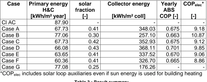
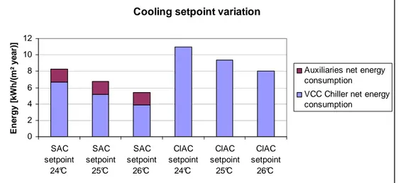
consumption is presented in figure 3 for each case. To convert net energy to primary energy, multiplication factor is 2.5 for electricity, 1 for gas (Belgian values). Base case A is already more energy efficient than classical air-conditioning. Care should be taken that cases A, B, C, D and G have no effect on thermal comfort in the building. Most impact on energy total primary energy consumption is the control of absorption chiller feeding temperature (Case D). Results are also pointing out that it is better to use solar energy for both heating and cooling (cooling only is case B, heating only is case G). On figure 4 is presented the influence of room set point temperature on net energy consumption. Solar air conditioning with 24°C set point temperature has nearly same consumption as classical air conditioning with 26°C set point.
Case Primary energy H&C [kWh/m² year] solar fraction [-] Collector energy [kWh/m² coll] Yearly ABS COP [-] COPelec* [-] Cl AC 87.90 - - - - Case A 67.73 0.41 348.03 0.675 9.18 Case B 77.06 0.30 257.10 0.663 10.87 Case C 67.73 0.42 352.93 0.675 9.12 Case D 66.08 0.43 368.11 0.701 9.85 Case E 63.65 0.41 337.52 0.670 9.06 Case F 60.36 0.41 326.70 0.665 8.86 Case G 77.08 0.25 176.26 - -
*COPelec includes solar loop auxiliaries even if sun energy is used for building heating
Table 3 : Result summary
Primary energy for heating and cooling
0.00 -22.95 -12.33 -22.95 -24.83 -27.60 -31.33 -12.32 0 10 20 30 40 50 60 70 80 90 100 Cl A C Cas e A Cas e B Cas e C Cas e D Cas e E Cas e F Cas e G E n e rg y [ k W h /( m ² y e a r) ]
primary energy for heating primary energy for cooling Solar cooling auxiliaries primary energy cons. Energy consumption reduction
Figure 3 : Primary energy for heating and cooling
Conclusion
A complete office building solar air conditioning modular application was presented. Simulation features were defined closely to real life operation : Typical European office building was defined, almost all air-conditioning devices have their parameters taken in manufacturers data sheets.
Results are given in terms of primary and net energy consumption. Different scenarios are defined and revealed impact of control on energy consumption. Compared to classical air conditioning, energy savings reach 20 to 30% using solar air-conditioning. Room temperature set point as also great impact.
Other investigations about control can be done in further work. For example, cooling circuit flow and cooling set point variations seems to be crucial for energy savings.
Cooling setpoint variation
0 2 4 6 8 10 12 SAC setpoint 24°C SAC setpoint 25°C SAC setpoint 26°C ClAC setpoint 24°C ClAC setpoint 25°C ClAC setpoint 26°C E n e rg y [ k W h /( m ² y e a r) ]
Auxiliaries net energy consumption
VCC Chiller net energy consumption
Figure 4 : Net energy for cooling with different setpoints
References :
[1] (2007). Solar Air-Conditioning, 2nd International Conference Proceedings. Regensburg, Germany, Ostbayerisches Technologie-Transfer-Institut e.V. [2] Thomas, S; et al. (2008). Simulation based energy consumption calculation of an
office building using solar assisted air-condtioning , Eurosun 2008 conference Lisbon Proceedings.
[3] Thomas, S; et al. (2009) Dynamic simulation of a complete solar assisted air-conditioning system in office building using TRNSYS, Building Simulation conference Glasgow Proceedings.
[4] Crawley D.B; et al. (2008) Contrasting the capabilities of building energy
performance simulation programs. Building and Environnement 43 pages 661-673.
[5] Casals X.G. (2006) Solar absoprtion cooling in Spain: Perpectives and outcomes from the simulation of recent installations. Renewable energy 31 pages 1371-1389.
[6] Henning, H.-M. (2008) Solar Cooling Components and Systems - an Overview, Solar Air-Conditioning international seminar, Munich,Germany.