HAL Id: hal-01354992
https://hal.inria.fr/hal-01354992
Submitted on 4 Nov 2016
HAL is a multi-disciplinary open access
archive for the deposit and dissemination of sci-entific research documents, whether they are pub-lished or not. The documents may come from teaching and research institutions in France or abroad, or from public or private research centers.
L’archive ouverte pluridisciplinaire HAL, est destinée au dépôt et à la diffusion de documents scientifiques de niveau recherche, publiés ou non, émanant des établissements d’enseignement et de recherche français ou étrangers, des laboratoires publics ou privés.
Distributed under a Creative Commons Attribution - NoDerivatives| 4.0 International License
Demo abstract : FPGA-based implementation of a
flexible FFT dedicated to LTE standard
Mai-Thanh Tran, Emmanuel Casseau, Matthieu Gautier
To cite this version:
Mai-Thanh Tran, Emmanuel Casseau, Matthieu Gautier. Demo abstract : FPGA-based implementa-tion of a flexible FFT dedicated to LTE standard. Conference on Design and Architectures for Signal and Image Processing (DASIP), Demo Night, Oct 2016, Rennes, France. Conference on Design and Architectures for Signal and Image Processing (DASIP), Demo Night, pp.2, 2016. �hal-01354992�
Demo abstract: FPGA-based implementation of a
flexible FFT dedicated to LTE standard
Mai-Thanh Tran, Emmanuel Casseau and Matthieu Gautier
University of Rennes 1, IRISA Lab., France
Abstract— Field Programmable Gate Array (FPGA) technology is expected to play a key role in the development of Software Defined Radio platforms. To reduce design time required when targeting such a technology, high-level synthesis tools can be used. These tools are available in current FPGA CAD tools. In this demo, we will present the design of a FFT component for Long Term Evolution standard and its implementation on a Xilinx Virtex 6 based ML605 board. Our flexible FFT can support FFT sizes among 128, 256, 512, 1024, 1536 and 2048 to compute OFDM symbols. The FFT is specified at a high-level (i.e. in C language). Both dynamic partial reconfiguration and run-time configuration based on input control signals of the flexible FFT will be shown. These two approaches provide interesting tradeoff between reconfiguration time and area.
Keywords—FPGA, FFT/iFFT, LTE, high-level synthesis
I. INTRODUCTION
Advanced wireless communication standards are designed with various requirements in terms of data transmission rate, spectral efficiency and multiple channel bandwidths. To fulfil these requirements, many configurations of the waveform (PHY layer) features are allowed such as the number of antennas, the coding rate, the modulation scheme or the number of subcarriers in the case of the Orthogonal Frequency Division Multiplexing (OFDM) modulation. In such a context, new needs of PHY layer implementations appear while the hardware implementation has to switch from one configuration to one another in a short time not to loose too many OFDM symbols.
An emergent technology that answers these new needs is Software Defined Radio (SDR) that allows both flexibility and fast prototyping capabilities from a high-level description [1]. However, when implementing the processing on Digital Signal Processors (DSPs), SDR suffers from important power consumption and limited performance as compared to dedicated hardware fabrics. FPGAs can be an interesting alternative to DSPs. FPGA-based SDR is an old paradigm [2] offering a good tradeoff between reconfiguration capability and processing power. Fast prototyping capability of an FPGA-based SDR can be achieved using High-Level Synthesis (HLS) tools to generate Register-Transfer Level (RTL) descriptions from high-level specifications. In this demo, we will show that run-time flexibility of a Fast Fourier Transform (FFT) can be achieved using two approaches: a) Dynamic Partial Reconfiguration (DPR) or b) run-time configuration based on input control signals.
II. DESIGN APPROACH
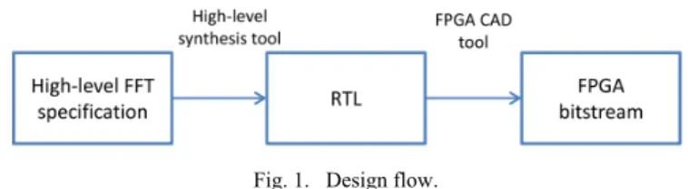
Among many configurations, Long Term Evolution (LTE) standard specifies that the computation of an OFDM symbol can be performed over several numbers of subcarriers among {128, 256, 512, 1024, 1536, 2048}. FFTs are used to compute the OFDM symbols, so that the required FFT sizes are {128, 256, 512, 1024, 1536, 2048}. To cope with these flexibility requirements, two approaches have been implemented: DPR that FPGAs can support and a multi-mode FFT component with control signals to switch between the different modes (i.e. FFT sizes). In both cases, the processing blocks are described at a high-level (C language). The design flow is shown in Fig 1. The CAD tool suite we use is Vivado from Xilinx. Vivado HLS tool is used to perform the high-level synthesis and provide the RTL descriptions. DPR is setup with PlanAhead. A Xilinx Virtex 6 FPGA is targeted as a ML605 board is used for the demo.
Fig. 1. Design flow.
With the DPR approach, there are as many partial bitstreams as there are FFT sizes. The partial bitstreams are generated from fixed size FFT specifications and the bitstreams are stored in the DDR memory. A software processor controls which partial bitstream has to be loaded into the reconfigurable partition at a particular time based on the required FFT size. Reconfiguration time depends on the bitstream size.
With the multi-mode FFT, the designer has to hand-code a dedicated processing block being intrinsically flexible. Input signals are used to control the modes. Algorithmic optimizations should be done so that the HLS tool can share the resources between the modes. In this case, only one partial bitstream is generated and only one clock cycle is required to switch from one particular FFT size to another one.
The high-level FFT specifications are based on the radix-2 Decimation-In-Time (DIT) algorithm, which is the simplest and most common form of the well-known Cooley-Tukey algorithm [3].
For the multi-mode FFT, a standard three-loop based structure was used for the FFT specification based on radix-2. A power-of-two point FFT with modes {128, 256, 512, 1024, 2048} has been specified and the HLS tool deals with the FFT size as a variable. A component with one main FFT core for these five different modes can thus be generated. By applying the Cooley-Tukey algorithm for the 1536-point FFT, three 512-point FFTs and one radix-3 function are required [4]. In practice, resource sharing between the power-of-two point FFT and the 1536-point FFT when they are both specified in a single high-level specification is not effective. We preferred to generate two partitions: one for the power-of-two point FFT only and one for the 1536-point FFT only. Then, a reconfigurable partition was finally created for the DPR of these 2 FFTs.
HLS not only reduces design time starting from a high-level specification as an input. It also allows design space exploration using compilation directives helping the user to meet design constraints such as area, latency and throughput. The user can thus easily tune its design based on its constraints and/or tradeoff between number of resources and latency. Due to the loop structure of the specifications and the data dependencies of the FFT, we used loop unrolling. More details can be found in [5].
III. PLATFORM USED FOR THE DEMO
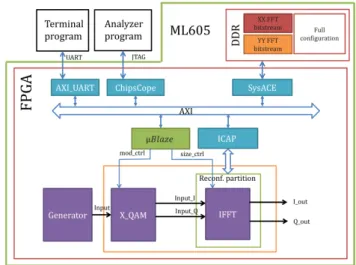
For the demo, the transmitter part of an OFDM-based like communication system will be presented (Fig. 2). A generator provides binary data to a multi-mode modulator (X_QAM) that can implement BPSK, QPSK, 16-QAM and 64-QAM. As we focus on the transmitter, iFFTs are implemented rather than FFTs. The system runs on the ML605 board. The terminal program provides the control signals to the MicroBlaze processor to control the type of the modulation and the size of the IFFT. The MicroBlaze is in charge of the FPGA reconfiguration. It controls the signals to load the partial bitstream from memory (DDR3) to the reconfigurable partition via ICAP.
With the dynamic reconfiguration, when the size of the iFFT is changed, the appropriate bitstream is loaded. Reconfiguration needs 32.9 ms to switch from one configuration to one another. It means many OFDM symbols are lost during this time 1. With the multi-mode FFT, when the
user switch from one power-of-two point FFT to one another, the power-of-two point FFT configuration is loaded once and the appropriate FFT is selected at runtime. However when the user switches from one power-of-two point FFT to the 1536-point FFT, the new bitstream must be loaded.
During the execution, the waveforms can be viewed using the analyzer program. ChipScope ILA provides the virtual I/O to help the analyzer program collecting the results. Fig. 3 shows the platform used for the demo. Data from ChipScope are
1 Reconfiguration time can be reduced, but it was not the main
goal of this work.
post-processed to display both the constellation of the modulation and the OFDM spectrum.
Fig. 2. FPGA-based system implementing an OFDM-based like communication system.
Fig. 3. Platform used for the demo.
REFERENCES
[1] J. F. Jondral. Software-Defined Radio: Basics and evolution to cognitive radio. EURASIP Journal on Wireless Communications and Networking, Issue 3, pp275-283, 2005.
[2] M. Cummings and S. Haruyama. FPGA in the Software Radio. IEEE Communications Magazine, Vol. 37, Issue 2, pp. 108-112, 1999. [3] James W. Cooley and John W. Tukey. An algorithm for the machine
calculation of complex Fourier series. Mathematics of Computation, Vol. 19, No. 90, pp 297-301, 1965.
[4] Freescale Semiconductor Incorporated. Software Optimization of DFTs and IDFTs Using the StarCore SC3850 DSP Core. Application Note AN3980, 2009.
[5] M-T. Thanh, M. Gautier and E. Casseau. On the FPGA-based implementation of a flexible waveform from a high-level description: Application to LTE FFT case study. International Conference on Cognitive Radio Oriented Wireless Networks (Crowncom), May 30 – June 1, Grenoble, France, pp. 545-557, 2016.