Superhydrophobic and icephobic surfaces prepared by RF-sputtered
polytetrafluoroethylene coatings
R. Jafari*, R. Menini and M. Farzaneh
NSERC / Hydro-Quebec / UQAC Industrial Chair on Atmospheric Icing of Power Network Equipment (CIGELE) and Canada Research Chair on Engineering of Power Network
Atmospheric Icing (INGIVRE) http://www.cigele.ca Université du Québec à Chicoutimi, Chicoutimi, QC, Canada
*Corresponding author, Département des sciences appliquées, Université du Québec à Chicoutimi, Saguenay, QC, G7H 2B1, Canada. [email protected]
Abstract
A superhydrophobic and icephobic surface were investigated on aluminum alloy substrate. Anodizing was used first to create a micro-nano structured aluminum oxide underlayer on the alloy substrate. In a second step, the rough surface was coated with RF-sputtered polytetrafluoroethylene (PTFE or Teflon®). Scanning electron microscopy images showed a “bird’s nest”-like structure on the anodized surface. The RF-sputtered PTFE coating exhibited a high static contact angle of ~ 165º with a very low contact angle hysteresis of ~ 3º. X-ray photoelectron spectroscopy (XPS) results showed high quantities of CF3 and CF2 groups, which are responsible for the hydrophobic behavior of the coatings. The performance of this superhydrophobic film was studied under atmospheric icing conditions. These results showed that on superhydrophobic surfaces ice adhesion strength was 3.5 times lower than on the polished aluminum substrate.
Keywords
Introduction
Ice accumulation on outdoor surfaces can sometimes cause major problems on structures used, for instance, in electrical power transmission and distribution (aluminum cables and towers), transportation (boats, airplanes and roads) and telecommunication networks (towers). Icephobic coatings appear to be an interesting solution to prevent ice accumulation [1]. While no coating is perfectly icephobic, some have been developed from which ice shedding requires very little energy [2-3]. Good correlation between hydrophobicity and reduction of ice-adhesion has been reported [4-5]. Indeed, superhydrophobic surfaces (water contact angle θ > 150º) have shown promising anti-icing performance [6]. A variety of methods have been used to fabricate superhydrophobic surfaces [7-12]. There are two main approaches to generate superhydrophobic surfaces: (i) creation of a rough surface from low surface energy materials and (ii) creation of a rough surface followed by a low surface energy material coating step. Many methods have been developed so far to promote surface roughness, including sol-gel, plasma treatment, electrodeposition, anodisation, hot-water immersion, template method, chemical treatment and lithography [13-20]. Anodic aluminum oxide has been proposed as a suitable industrial process for use in the burgeoning field of nanotechnology [21] for developing nano-pore structure films with advantage of improvement of corrosion and wear resistance [22-24]. Low surface energy coatings can be produced by deposition of low surface-energy materials such as fluorocarbons and silicones precursors [8,10,25]. Polytetrafluoroethylene (PTFE or Teflon®) is actually one of the best materials for reducing ice adhesion strength due to its low electrical permittivity of ~ 2.1, low surface energy and chemical stability [4]. However, PTFE is very difficult to deposit as a thin film principally because it cannot be readily dissolved in any solvent, which prevents
spin-coating deposition. Nano-emulsions of PTFE particles can be used for such a purpose [26]. However, this technique requires sintering temperatures above the PTFE melting point. On the other hand, a variety of CVD and PVD techniques have been used to deposit PTFE. The sputtering technique is widely used in electrical and mechanical industries; because the process is simple, time saving, and environmentally friendly, and the resulting coating has a uniform structure and excellent adhesion properties to most substrates [27-28]. Herein, a superhydrophobic surface with low contact angle hysteresis (CAH) was made by consecutive anodizing of aluminum and sputtering of PTFE to reduce ice accumulation on the surface of aluminum alloys.
Experimental section
Mirror-polished 6061 aluminum alloy coupons (2.54 cm × 2.54 cm × 0.15 cm) from Rio Tinto Alcan: Mg 1.0, Si 0.6, Cu 0.28, Cr 0.05, Zn 0.1, Fe 0.25 and Mn 0.15 (all in wt %) were used as the substrate. Prior to anodizing, the coupons were degreased using acetone, and then rinsed carefully with deionized water. Anodizing processes were carried out in 10 % w/w solution of H3PO4 at T = 18o C at 50 V during 90 min. The RF plasma-sputtering process was carried out in an HICP-600SB PECVD system, manufactured by Plasmionique Inc. The distance between the target (Teflon) and the substrates (aluminum) was set at 30 cm. After being evacuated to a base pressure of 2.0 × 10⁻⁶ Torr, argon gases were admitted into the chamber. The flow rate of the sputtering gas was controlled by an MKS mass flow controller (MFC) and set at 50 standard cubic centimeters per minute (sccm). The aluminum surface was pre-cleaned and pre-activated in 50 W plasma argon for 5 min [29]. The sputter deposition process was carried out under 50 W RF power for 20 minutes at 20 mTorr.
Sample surface morphology was examined using a LEO field emission scanning electron microscope (FESEM) and an atomic force microscope (AFM) (Digital Nanoscope IIIa by digital instruments). Water contact angle measurements were carried out using a Kruss DSA 100 goniometer (water drop volume ~ 4 µL). The static contact angles were acquired by fitting the symmetric water drops using the Laplace–Young method, which is theoretically considered to be the most accurate because it takes into account the distorted drop shape due to liquid weight. In order to measure the contact angle hysteresis, which is the difference between the advancing and receding contact angles, a commonly used experimental procedure was followed [30]. The advancing and receding contact angles
were measured by holding the water drop with a stationary needle in contact with the surface. The substrate was moved slowly in one direction using a micrometric screw. The surface chemical composition was examined using X-ray photoelectron spectroscopy (XPS) at three different spots for each sample (PHI 5600-ci spectrometer, Physical Electronics). Survey and high-resolution spectra were acquired at a detection angle of 45° with respect to the normal of the surface, using the Kα line of standard aluminum (Kα = 1486.6 eV) and magnesium (Kα = 1253.6 eV) X-ray sources, respectively. For high resolution analyses, the Mg anode was used to provide better resolution and improved chemical shift characterization and attribution.
Ice-adhesion strength measurements were made using the centrifuge adhesion test method [6]. Samples were attached to one end of aluminum beams and glaze ice (up to ~ 1 cm thickness) was accumulated in a refrigerated wind tunnel (v = 10 m.s-1, T = -10 ºC, water feed rate of 2.5 g.m-3 and average droplet size of ~ 80 μm). This ice geometry was enough to avoid cohesion failure and provide reproducible deicing results. The beam was spun at increasing rotational speed (T = -10 ºC) until ice detachment. The ice adhesion strength was assumed to be equal to the centrifugal force, F = mrω2, where m is the ice mass, r is the beam radius and ω is the rotation speed (rad.s-1). The shear stress was then calculated as τ = F/A, where A is the iced surface area. To reduce the bias caused by potential experimental errors, the adhesion reduction factors (ARF) were computed. ARF is the ratio between ice shear stresses of the bare polished aluminum and the coatings: ARF = τ(polished aluminum)/τ(coating).
Results and discussion
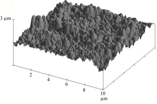
The FE-SEM image, see Fig. 1a, of an anodized aluminum surface is typical of such phosphoric acid processes leading to large nanopores having thin walls. A recent study on the morphological transformation of anodic aluminum oxide films during anodizing has shown that the growth process of the pores is divided into two different regimes [31]. In the first regime, pore diameters and depths increase linearly with time. In this regime, the solvent action of the cell walls played a leading role: the pores became increasingly wider and the cell walls progressively thinner. Then some nanopores broke into bigger pits (second regime), forming a so-called bird’s nest-like structure with nanoscale interlaced sheets and wires. Taking into account the relatively long anodizing time (90 min) in this study, comparison with the results described in [31] showed that the morphology corresponds to the second regime process. Figure 1a reveals the presence of some nanopores with a diameter of about 100 nm surrounded by a bird’s nest structure. Figure 1b shows the anodized surface covered by RF-sputtered PTFE thin film. Comparing both figures shows that the depth and diameter of the nanopores decreased slightly after PTFE thin film deposition. However, the nanopores are still present after PTFE deposition. Fig. 2 shows the AFM image of a PTFE film deposited on the anodized surface. It shows the nano-size and micro-size surface roughness (rms ~120 nm), resembling the lotus leaf morphology.
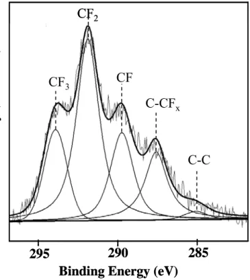
XPS analysis was carried out to determine the chemical composition of the RF-sputtered PTFE coatings deposited on the anodized surface. A peak-fitted spectrum for the C1s core level is shown in Fig. 3. The high-binding-energy structure is indicative of the existence of carbon-fluorine bonds. The spectrum can be satisfactorily fitted by a combination of five distinct peaks: the peak at 285.1 eV corresponds to C-C moieties, the peak at 287.5 eV to C-FX species (hydrocarbon adjacent to a fluorocarbon group with x = 1 to 3), the
peak at 289.6 eV to CF groups, the peak at 291.8 eV to CF2 and the peak at 293.9 eV is due to CF3 groups [26, 32]. The binding energy assignments and the relative peak area of each component are shown in Table 1. It is well known that the presence of fluorine groups on the surface can lower the surface energy [33]. The atomic ratio of F/C was found to be around 2, which is higher than the results of other studies on the deposition of RF-sputtered PTFE coatings [32, 34-35]. Zisman et al. reported that the surface free energy decreased in the order –CH2> -CH3> -CF2>- CF3 [36]. Table 1 clearly shows the presence of high amounts of -CF3 and -CF2 groups on the RF-sputtered PTFE coating, which reduces the surface energy of anodized aluminum surfaces.
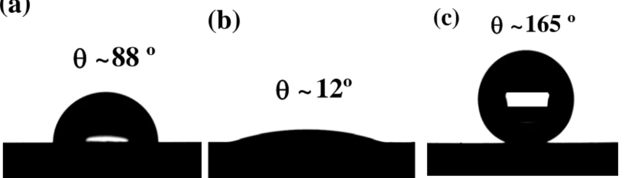
The water contact angles of different surfaces were examined, as illustrated in Figs. 4a to 4d. A polished aluminum surface showed a water contact angle of about 88º, as seen in Fig. 4a. After anodizing, the contact angle decreased to 12º (Fig. 4b), i.e., water droplet spread thereon. The low contact angle could be explained by the 3-D capillary effect, due to the wicking and imbibition in the broken sheets and nanopores, the water droplet spread quickly [31]. The contact angle of a Teflon-like coating deposited on a polished aluminum surface (without anodization) is about 114 ± 1º. The RF-sputtered PTFE coating on the anodized surface showed the superhydrophobic behavior (Fig. 4c) for an anodization time of 90 min. The time of 90 min for anodization was obtained by optimization of contact angle of RF-sputtered PTFE coating for different time of anodization (Table 2). Measurement of the contact angle hysteresis is very important to properly characterize the superhydrophobic surface [21]. For instance, a high contact angle water droplet deposited
van der Waals force between the water droplet and the solid surface. Hence, adhesion is proportional to the surface area of the liquid-solid interface, which can be described by two different models: Wenzel and Cassie-Baxter [38]. In Wenzel’s model (homogenous interface), the roughness can increase the area of liquid-solid interface and the adhesion between them is strong. Concerning the Cassie and Baxter model (composite interface), it showed that air (or gas) pockets are trapped in the rough surface cavities, resulting in a composite solid–liquid–air interface, as opposed to the homogeneous solid–liquid interface. Due to the small solid-liquid contact area in the Cassie-Baxter state, the hysteresis is very small and a liquid drop can roll off easily.
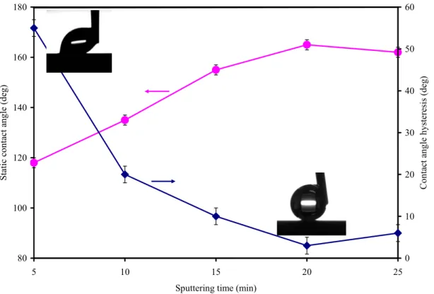
Variations of the static contact angle and the contact angle hysteresis of Teflon-like coatings deposited on aluminum surfaces as a function of sputtering time were shown in Fig. 5. By increasing sputtering time, contact angle increased until 20 minutes when this value became constant. Additionally, the variation of contact angle hysteresis with sputtering time showed the decrease of CAH due to more homogenous recovery of Teflon-like coatings. The contact angle hysteresis measurements showed an ultralow CAH of about 3º for a sputtering time of 20 min. Therefore, these results (high static contact angle and ultralow CAH) clearly showed that a composite interface (Cassie-Baxter state) was formed between the PTFE coating on an anodized surface and the water droplet. To assess the icephobic characteristics of the RF-sputtered PTFE coatings, ice was accumulated using a refrigerated wind tunnel and ice adhesion was measured using the centrifuge method. Table 3 displays the results of icephobicity tests for polished aluminum and the RF-sputtered PTFE coating on polished and anodized aluminum surface. In the literature, the ARF value of flat PTFE compared to aluminum is 2 [39]. However, the ARF value of RF-sputtered PTFE coating on polished surface was more than 2 (2.3) due to the presence CF3 groups. Also, these results have shown a considerable
reduction of ice adhesion using anodized and RF-sputtering PTFE coatings. Therefore, the improved icephobicity of the RF-sputtering PTFE coating on anodized surface is due to the combined effects of enhanced roughness and the high ratio of CF3 species, see XPS results. Additionally, the very low CAH value of the RF-sputtered PTFE coatings (3o) is in accordance with the strong icephobic character. In fact, it is now usually accepted that coatings having CAH < 5o are strongly icephobic [3].
Conclusion
Superhydrophobic and icephobic surfaces were created using two inexpensive industrial processes. Anodizing aluminum generates a micro-nanostructure and RF sputtering deposits the PTFE coating on the anodized surface. A high water contact angle of ~165 º with a very low contact angle hysteresis of ~3º were obtained from the RF-sputtered PTFE coating on an anodized surface. XPS analyses showed large amounts of CF3 and CF2 groups on the RF-sputtered PTFE coating, which contributes to the low surface energy of this film. Under atmospheric icing conditions, this superhydrophobic film showed an ice-adhesion strength 3.5 times lower than a polished aluminum surface.
Acknowledgements
This work was carried out within the framework of the NSERC/Hydro-Quebec/UQAC Industrial Chair on Atmospheric Icing of Power Network Equipment (CIGELE) and the Canada Research Chair on Engineering of Power Network Atmospheric Icing (INGIVRE) at Université du Québec à Chicoutimi. The authors would like to thank the CIGELE partners (Hydro-Québec, Hydro One, Réseau Transport d’Électricité (RTE) and Électricité de France (EDF), Alcan Cable, K-Line Insulators, Tyco Electronics, Dual-ADE, and FUQAC) whose financial support made this research possible. The authors also wish to thank Marc Raggi for his assistance in sample preparation and characterization, and are grateful to Hélène Grégoire (National Research Council Canada, ATC, Saguenay) for SEM analysis.
References
[1] M. Farzaneh, Atmospheric Icing of Power Networks, Springer, Berlin, 2008, p.381. [2] V.F. Petrenko, S. Peng, Can. J. Phys. 81 (2003) 387-393.
[3] D.K Sarkar, M. Farzaneh, J. Adhes. Sci. Technol. 23 (2009) 1215-1237. [4] R. Menini, M. Farzaneh, Surf. Coat. Technol. 203 (2009) 1941-1946. [5] H. Saito, K. Takai, G. Yamauchi, Surf. Coat. Int. 80 (1997) 168-171. [6] S.A. Kulinich, M. Farzaneh, Appl. Surf. Sci. 255 (2009) 8153-8157.
[7] X. Zhang, F. Shi, J. Niu, Y. Jiang, Z. Wang, J. Mater. Chem. 18 (2008) 621-633. [8] M. Ma, R. M. Hill, Curr. Opin. Colloid Interface Sci. 11 (2006) 193-202.
[9] P. Roach, N. J. Shirtcliffe, M. I. Newton, Soft Matter 4 (2008) 224-240. [10] A. Nakajima, J. Ceram. Soc. Jpn. 112 (2004) 533-540.
[11] J. Fan, Y. Zhao, Langmuir 26 (2010) 8245–8250
[12] W.J. Khudhayer, R. Sharma, T. Karabacak, Nanotechnology 20 (2009) 275302. [13] D.K. Sarkar, M. Farzaneh, R.W. Paynter, Mater. Lett. 62 (2008) 1226-1229. [14 S. Ren, S. Yang, Y. Zhao, T.Yu , X. Xiao, Surf. Sci. 546 (2003) 64-74.
[15] M. A. Aegerter, R. Almeida, A. Soutar, K. Tadanaga, H. Yang, T. Watanabe, J. Sol-Gel Sci. Technol. 47 (2008) 203-236.
[16] E. Perre, L. Nyholm, T Gustafsson, P.-L. Tabern, P. Simon, K. Edström, Electrochem. Commun. 10 (2008) 1467-1470.
[17] R. Menini, M. Farzaneh, Polym. Int. 57 (2008) 77-84. [18] X. Zhao, W. Li, Surf. Coat. Technol. 200 (2006) 3492-3495. [19] D.K. Sarkar, M. Farzaneh, Appl. Surf. Sci. 254 (2008) 3758-3761.
[20] R. Frenzel, C. Blank, K. Grundke, V. Hein, B. Schmidt, F. Simon, M. Thieme, H. Worch, J. Adhes. Sci. Technol. 23 (2009) 469-482.
[21] D. Kim, W. Hwang , H.C. Park , K.-H. Lee, Current Applied Physics 8 (2008) 770-773.
[22] H. Wang, D. Dai, X. Wu, Appl. Surf. Sci. 254 (2008) 5599-5601.
[23] S-K. Hwang, S-H. Jeong, H-Y. Hwang, O-J. Lee, K-H. Lee, Korean J. of Chem. Eng. 19 (2002) 467-473.
[24] S. Hohne, C. Blank, A. Mensch, M. Thieme, R. Frenzel, H. Worch, M. Muller, F. Simon, Macromol. Chem. Phys. 210 (2009) 1263-1271.
[25] H.J. Lee, S. Michielsen, J. Polym. Sci., Part B: Polym. Phys. 45 (2007) 253-261. [26] P. Gonon, Eur. Phys. J. Appl. Phys. 32 (2005) 15-21.
[27] S. Iwamori, J. Vac. Soc. Jpn. 50 (2007) 619-624.
[28] H.J. Qiu, Y.B. Fu, D. Wang, X.X. Yang, K.Y. Sui, Z.L. Ma, Surf. Coat. Technol., 131 (2000) 177-180.
[29] R. Jafari, M. Tatoulian, M. Morscheidt, F. Arefi-Khonsari, Reactive & Functional Polymers 12 (2006) 1757-1765.
[30] M. Callies, Y. Chen, F. Marty, A. Pépin , D. Quéré, Microelectron. Eng. 78–79 (2005) 100-105.
[31] J. Ye, Q. Yin, Y. Zhou, Thin Solid Films 517 (2009) 6012-6015.
[32] V. Stelmashuk, H. Biederman, D. Slavinska, J. Zemek, M. Trchova, Vacuum 77 (2005) 131-137.
[33] E. Burkarter, C.K. Saul, F. Thomazi, N.C. Cruz, L.S. Roman, W.H. Schreiner, Surf. Coat. Technol. 202 (2007) 194-198.
[34] G. Tang, X. Ma, M. Sun, X. Li, Carbon 43 (2005) 345-350.
[35] D.Y. Wi, I.W. Kim, J. Kim, Fibers and Polymers 10 (2009) 98-101. [36] E.F. Hare, E.G. Shafrin, W.A. Zisman, J. Phys. Chem. 58 (1954) 236-239.
[37] W. Chen, A.Y. Fadeev, M.C. Hsieh, D. Oner, J. Youngblood, T.J. McCarthy, Langmuir, 15 (2009), 3395-3399.
[38] Q. F. Xua, J.N. Wang, New J. Chem. 33 (2009) 734-738.
[39] N.D. Mulherin, R.B. Haehnel, Ice Engineering Technical Note, 03-4 (October 2003).
Fig. 1: FESEM images of (a) anodized aluminum and (b) RF sputtered PTFE coating deposited on anodized aluminum surface.
2 6 8 4 10 3 µm µm
Fig. 2. 3D AFM image of the surface of PTFE film deposited on the anodized aluminium surface.
CF
3CF
2CF
C-CF
xC-C
285
290
295
Intensity (counts.s
-1)
Binding Energy (eV)
CF
3CF
2CF
C-CF
xC-C
285
290
295
Intensity (counts.s
-1)
Binding Energy (eV)
θ ~88 º
(a)
θ ~ 12º
(b)
(c)
θ ~165 º
Fig. 4: Images of 4 μL (a) sessile water droplets on polished aluminum, (b) sessile water droplets on anodized aluminum and (c) sessile water droplets on RF-sputtered PTFE coating deposited on an anodized aluminum surface.
80 100 120 140 160 180 5 10 15 20 25
Sputtering time (min)
St atic c ontac t a ngle (d eg ) 0 10 20 30 40 50 60 Conta ct an gle hysteresis (deg )
Fig. 5: Variation of static contact angle and contact angle hysteresis of RF-sputtered PTFE coatings deposited on anodized aluminum surfaces as a function of sputtering time.