A testbench for ARGOS: integration of sub-systems and
validation of the wavefront sensing
Gilles Orban de Xivry
a, Sebastian Rabien
aa
Max Planck Institut f¨
ur extraterrestrische Physik, Garching, Germany
ABSTRACT
Argos, the wide field Laser Guide Stars adaptive optics system for the Large Binocular Telescope, is now entering its installation phase. In the meanwhile, we have started a test bench in order to integrate various Argos sub-systems and demonstrate its wavefront measurements. To this objective, we first validate three key components of the Argos wavefront sensor which we then integrate together. The test bench therefore comprises the Argos wavefront camera system - including a large frame, fast framerate, high quantum efficiency and low readout noise pnCCD -, the slope computer, and a optical gating unit.While we present here the demonstration of those three key components, it is also a step to their system level integration that enables us to validate the wavefront measurements in term of noises, timing and computation. In the near future, those system will be integrated to the wavefront sensor system of Argos.
Keywords: Adaptive Optics Wavefront Detector - pnCCD - Slope computer - Centroid Calculation - Optical gating
1. INTRODUCTION
Argos1is the laser guided ground layer adaptive optics system of LBT. With its three laser guide stars, it will enhance the imaging and spectroscopic capabilities of the near-infrared imager and multi-object spectrograph LUCI2with a typical gain of 2-3 in FWHM and 4-9 in sensitivity under various seeing conditions. Among many various interests and science cases brought by this “seeing-enhancement”, the trade-off between spatial resolution and signal to noise combined with the LUCI instrument will be particularly optimum for the study of high redshift galaxies.
The system uses three 18W pulsed green laser for each LBT’s eye, therefore producing 3 Laser Guide Stars (LGS) at 12km distances.3 The backscattered light, after being split from the scientific near-infrared wavelength, enters the wavefront sensor system where the light is optically gated individually for each LGS, falls on a common lenslet array creating three Shack-Hartmann patterns on the single Argos pnCCD camera.
The large pnCCD itself features split frame transfer, frame store operation and column-parallel readout, and therefore reaches frame rates up to 1kHz while preserving a low readout noise.
The data are then transferred to the Argos slope computer (slope BCU), a DSP-based real time computer performing the slope computation for the three SH patterns at once.
By the large amount of data and the fast rate, this is both challenging in term of detector and computation technology.
We present, in Section 2, the sub-systems - i.e. the Argos pnCCD camera, the slope computer, and the optical gating unit - and their individual validation. The testbench, integration, and measurements of the combined three systems are presented in Section 3.
Further author information: (Send correspondence to G. Orban de Xivry) E-mail: [email protected]
2. ARGOS INTEGRATED SUB-SYSTEMS
We present here three sub-systems of the ARGOS wavefront sensor, i.e. the Argos pnCCD camera, the slope computer and the optical gating. These three components are closely linked at the system level in term of timing, configuration, and possible noise effects. Combining these three sub-systems together is a step forward to the wavefront sensor integration and the validation of the wavefront measurements.
2.1 PN-CCD wavefront sensor camera
The Argos wavefront sensor (WFS) uses a single detector to sense the wavefront from its 3 LGS: the Argos pnCCD camera - developed by PNSensor GmbH. Each Shack-Hartmann (SH) array features 15×15 sub-apertures each 8×8 pixels (with a pixel scale of 0.5600/px).
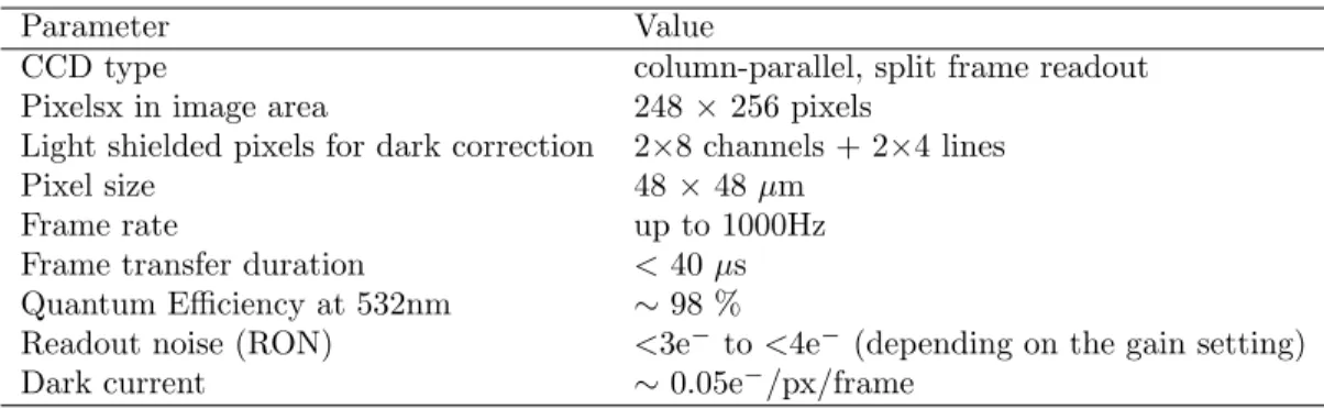
The Argos pnCCD camera4 is a unique adaptive optics camera benefiting of the high quality of the pnCCD chip, i.e. frame rates up to 1kHz, high quantum efficiency, large imaging area, and low noise. A summary of the key pnCCD characteristics is given in table 1.
Table 1. Summary of key pnCCD specifications.
Parameter Value
CCD type column-parallel, split frame readout Pixelsx in image area 248× 256 pixels
Light shielded pixels for dark correction 2×8 channels + 2×4 lines
Pixel size 48× 48 µm
Frame rate up to 1000Hz Frame transfer duration < 40 µs Quantum Efficiency at 532nm ∼ 98 %
Readout noise (RON) <3e− to <4e− (depending on the gain setting) Dark current ∼ 0.05e−/px/frame
All the ARGOS pnCCD camera electronics fits now in a 1900rack and uses 6 HU. It includes the power supplies, a Peltier controller module (the cooling is performed by two double-staged thermoelectric modules and allows temperature below -30°C), and a cPCI backplane interface. The later one contains a cPCI PC (comprising a standalone software allowing remote control), the pattern generator (allowing external synchronization), a housekeeping card, and two optical ADC.
These two ADC receive the eight analog signals from the camera and, after digitalization, send the data through two optical fibers - the total data rate being approx. 140MBytes/sec - to our ARGOS wavefront computer, described here after in Section 2.2.
Although at the state-of-art, the pnCCD suffers of a time variant (line-by-line variation) electronics noise, which - if it cannot be properly corrected - has a strong impact on the AO performances. This particular noise needs to be corrected by the use of reference pixels, e.g. using the eight reference covered channels per quadrant (similarly affected by the common-mode noise) or using any pixels outside the three SH pupil images - therefore not exposed to light.
In the early development and testing of the Argos pnCCD camera, this correction (i.e. 8 covered channels) has been shown, in some cases, to be insufficient : the variation was not sufficiently constant along individual lines (therefore leaving strong residuals after subtraction). Hence, dedicated effort has been conceded to pin-point the problem and developped dedicated power-supplies.
At the current state, this noise is no longer considered to compromise the AO performances.
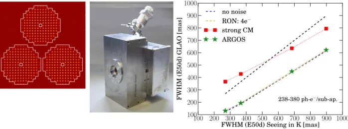
We demonstrate it by a dedicated AO simulation based on the YAO simulation tools∗, e.g. see Figure 1 right. We compare the ground-layer adaptive optics performances for different detector backgrounds in various seeing and photon fluxes conditions:
∗
a “perfect case” with no photon nor readout noise, a “reference case” with photon noise and 4e−RON, the current Argos pnCCD background,
the “worst case” of the former and uncorrected background from the pnCCD.
The results are illustrated in Figure 1 for a conservative flux level, i.e. for a flux level of <380photons/subap./msec well below the nominal foreseen flux level for Argos of >700photons/subap./msec (the minimal flux requirements being >300photons/subap./msec.). We can clearly see that in this regime and with those noises, the detector delivers the optimum performances and is not limiting the AO correction.
100 200 300 400 500 600 700 800 900 1000
FWHM (E50d) Seeing in K [mas]
100 200 300 400 500 600 700 800 900 1000 F W H M (E 5 0 d ) G L A O [m a s] 238-380 ph-e−/sub-ap. no noise RON: 4e− strong CM ARGOS
Figure 1. (Left) Simulated 3 SH patterns combined to the pnCCD background after correction - the pnCCD will sense 3SH pupil with 15×15 subapertures. (Middle) the Argos pnCCD camera housing with the entrance window, and backplane electronics. (Right) Illustration of GLAO simulation with various WFS detector backgrounds: GLAO FWHM versus the uncorrected FWHM in the K-band (as a proxy for the PSF FWHM we use the 50% encircled energy diameter). The flux regime illustrated here is about the minimum flux requirement for Argos and in any case lower than the nominal foreseeen flux of >700 photons/subap./msec. In this regime, the Argos pnCCD leads to optimum performances.
2.2 Slopes Basic Computation Unit
The Argos slope computer (also named slope/LGS Basic Computation Unit, BCU) is a custom development by Microgate s.r.l. for Argos and, being a DSP-based real time computer (see Figure 2), has been optimized to ensure minimum latency from the input data to the output slopes.
The primary task of the LGS BCU is obviously to acquire the pnCCD frames through two optical fibers, applies the necessary corrections (i.e. offset and common-mode subtractions, and gain correction), compute the slopes from the 3 LGS SH pupils and send the results to the RTC BCU of the LBT secondary deformable mirror (DM).
The BCU features also two high-voltage control (HVC) boards that, based on the measured LGS slopes, enable us to control the LGS tip-tilt mirrors for field stabilization.5
The additional interfaces (see Figure 2 left) are the acquisition of the NGS tip-tilt slopes (featuring dedicated APD modules and computing unit6) through a serial interface, and the possibility to acquire additional slopes from either the current LBT FLAO7
MG HV controller P:_ TI ni rr_r FT slpe calcudtur MPIIR Pdckplane iritertace swial P54:: pnCCD D,PO hoard Switch BCU Ethernet FLAO BCU 1 ARGOS SUPERSOR J
i'b
I'll4p.
transfers the final slopes vector to the LBT secondary mirror (which goes first to a “switch BCU” see Figure 2) where a dedicated computing unit reconstructs the phase and control the DM shape.
Figure 2. (Left) The interfaces scheme of the Argos slope computer, in red are represented the optical fiber links. (Top left) Picture of the BCU with its two HVC boards controlling the three LGS tip-tilt mirrors in the WFS system, the two pnCCD optical fiber links and the ethernet cable for configuration and diagnostics download. (Bottom left) Seven low-ordre Karhunen-Lo`eve modes obtained by uploading simulated SH images to the BCU, triggering the slope computation and then off-line reconstructing the WF by zonal integration.
Although being a relatively classic center of gravity, the algorithm chosen for the centroiding computation is generalized (based on various proposed algorithms8–10) and give some flexibility for optimization. The imple-mented centroiding algorithm is as follows:
∀ sub-ap. a :
xa = γaK−1 N X
i;Ii,a>Ia;T
xiWi,a(Ii,a− Ia;T)n
ya= γaK−1 N X
i;Ii,a>Ia;T
yiWi,a(Ii,a− Ia;T)n with K, the normalization factor, defined as : K =
N X
i;Ii,a>Ia;T
Wi,a(Ii,a− Ia;T)n
(1)
where a is the sub-aperture index, i the pixel index within the sub-aperture a, and Ii,a is the intensity of the pixel i in the sub-aperture a from the current pnCCD image. The vector Wi,a is a weighting function that enable us to easily window or null any sub-aperture, it can also be used in a weighted center of gravity scheme
if a reference spot image is measured (attenuating noise effects but introducing some non-linearity that can be partially calibrated by γa). The implemented flux threshold Ia;T is implemented in a generalized form: Ia;T = Ia;T ;cst+ αIa;max. The constant threshold Ia;T ;cst is a configurable minimum flux level (typically 3× the read-out-noise); the dynamical part αIa;max is defined as a typical fraction α of the maximum flux level of the current sub-aperture and image Ia;max, it can be used to mitigate spot elongation effects. Finally, the factor n can be either 1 or 1.5. In the latter case this results in approximately weighting the centroiding computation by the respective pixel signal-to-noise ratio.
As a demonstration of the BCU operability and computation validity, we inject images with simulated SH pattern based on the Karhunen-Lo`eve (K-L) basis. After upload of the images, proper configuration and trig-gering of the slope computation, we retrieve the computed slopes through the available BCU diagnostics and perform an off-line wavefront reconstruction using a iterative integration scheme (see Section 3). The result for one SH pupil and for 7 K-L modes matches the simulated input and is illustrated Figure 2 right.
We further test the BCU by using pnCCD measurements, see Section 3, validating the frame correction part.
2.3 Optical Gating Unit: ARGOS Pockels Cells
As Argos is based on pulsed Rayleigh lasers focused at approximately 12km distance, the WFS system uses Pockels cells to gate out the desired slice of the backscattered light, i.e. at 12km distance over approx. 300m. Each LGS beam is individually gated, the three Pockels cells units being synchronously controlled by a common driver.
Those optical gating units implement the following chain of optical components, as also illustrated in Figure 3 left: a first polarizer, an electro-optical modulator (BBO crystal), a polarization rotator, a second BBO crystal, and a last polarizer.
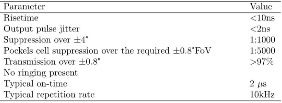
The aferomentioned scheme allows a high transmission/suppression rate and relatively large field of view with little artifacts and large uniformity. The key characteristics are summarized in table 2:
Table 2. Summary of Argos Pockels cells characteristics and application.
Parameter Value
Risetime <10ns
Output pulse jitter <2ns
Suppression over±4° 1:1000
Pockels cell suppression over the required±0.8°FoV 1:5000 Transmission over±0.8° >97% No ringing present
Typical on-time 2 µs
Typical repetition rate 10kHz
This optical gating therefore allows us to typically “open” for approx. 2µs (beacon vertical extent of 300m) every 100µs, therefore following the pulses from the ARGOS lasers.
3. TEST BENCH AND RESULTS
Modus operandi. In the purpose of integrating these various components in realistic conditions, we build up a test bench which, in effect, consists in a 5mm diameter collimated beam passing through one Pockels cells, a lenslet array, a magnification optical setup to match the desired pixel size and spacing between the spots, and finally the pnCCD chip on which is imaged the lenslet array. The bench is shown in Figure 4.
Figure 3. (Left) One Argos Pockels cell unit with on top its high voltage connector. From left to right the polarizer I, the first BBO crystal with its transversal electrodes, the Quartz rotator, the second BBO, and the polarizer II. (Middle) The field dependent (by using a input convergent light) transmission through the Pockels cell; the upper dashed line shows the transmission of the BBO crystal when the voltage is applied; the solid line shows the transmission without voltage; the dashed-dotted line shows the transmission in the “closed” state of the Argos Pockels cell; The bottom curve shows the suppression of the polarizers alone. (Right) top, transmission through a single 12mm thick BBO; middle, field dependent transmission in the “open” state of the Argos Pockels cells; bottom, suppression of the cell in the “closed” state.
A common pulse generator controls the high voltage driver of the Pockels cell and triggers the frame transfer of the pnCCD after an appropriate delay. Similarly to the final operation mode, the Pockels cell are typically “opened” ten times (corresponding to the 10 laser pulses operated at a 10kHz repetition rate), before reading out the detector. Moreover, the switching time is appropriately delayed to not fall whithin the pnCCD image transfer duration, i.e. approx. 40µs from the image to the framestore area.
As the camera ADCs and the BCU cannot presently be interfaced in real time, we acquire a data cube and upload frame by frame the data to the BCU. Once the BCU is correctly configured (e.g. offset map uploaded, slope parameters settings, etc.), the computation is triggered and the resulting slopes are acquired through the BCU diagnostics mechanism. We then use those slopes for analysis i.e. to study the centroiding accuracy -and to derive the wavefront. The wavefront is simply computed by iterative integration of the slopes (also shown Figure 2 right) and serves here only a qualitative purpose. The slope computation performed by the BCU and the wavefront reconstruction have been previously validated as illustrated by the K-L modes computation, see Section 2.2.
Pockels Cell
Pockels Cell Driver
pnCCD
BCU LA
Figure 4. (Left) Schematic of the optical bench integrating three key components of the Argos wavefront sensing: the Pockels Cells, the pnCCD camera and the slope computer (not on the picture). (Right) Actual bench.
Analysis and Results. As the high-voltage driver of the Pockels cell is relatively close to the camera, itself sensitive to power supply voltages as illustrated by its common-mode noise variation, we evaluate the pnCCD noises (RON and common-mode) and therefore verify that the fast high-voltage switching is not introducing any EMC problems.
Based on our measurements, we illustrate here the configurability and the advantages of the general formu-lation of the centroiding computation. A Shack-Hartmann pattern is produced on the pnCCD with a similar pupil and subaperture size as for Argos, i.e. approx. 15 subapertures along the pupils diameter each 8×8 pixels wide. The FWHM is approximately 2.5pixels but is relatively elongated due to the optical setup.
Acquiring a data cube of 200 frames, the slopes are then computed for each frames by the BCU. From the retrieved slopes, subaperture fluxes and centroiding accuracies (standard deviation) are computed and compared to each other. The flux for each subaperture is the sum of the pixel fluxes minus the flux threshold, see also Equation 1.
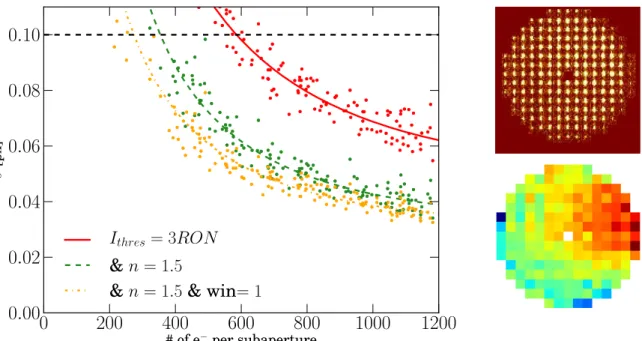
We illustrate here three different algorithms allowed by the algorithm implemented in the Argos BCU: A simple 3× RON fix threshold - that we keep for all the following algorithm -,
A “signal-to-noise” ratio weighting by using the power factor n = 1.5,
Same weighting with in addition a windowing of the subaperture: using a 6×6 subaperture instead of 8×8 (the flux is still computed on the 8×8 subaperture),
The centroiding accuracy is given in Figure 5, each point represents a subaperture and the curves are the respective fit. In our particular case, we clearly see the improvement brought by each algorithm, in particular the weighting by the signal-to-noise ratio. It is as well important to note that in the simple case of the 3×RON fix threshold, the centroiding accuracy is identical in both the x and y axis of the CCD frame, which further confirm that the common-mode noise residuals do not impact the measurements (see also Section 2.1). This is no longer true for the two other algorithms which combined to the spot elongation give discrepancies in the x and y accuracies.
The expected backscattered flux from the Argos lasers should results in more than 700 photons per sub-aperture per milli-seconds. Considering the high QE of the pnCCD, this results similarly in more than 700e− per subap. per msec.. As also illustrated in Figure 5 left, this should always be enough to perform accurate slope measurements, with a large margin for improvements allowed by the general algorithm.
4. CONCLUSIONS
We have presented here the validation of three key components of the Argos wavefront sensing system. Apart from classical CCD analysis, the Argos pnCCD has been validated by the used of close-loop simulation showing that, in the Argos regime, the detector does not limit the close loop performances, regardless of its particular noise. The principal task of the Argos BCU has been demonstrated by the computation of K-L simulated SH patterns but has well by the use of pnCCD data with the appropriate image corrections. Finally, the fast switching time and the quality of the transmission and suppression of the Argos Pockels cells have also been demonstrated.
These three components have then been integrated in an optical setup and jointly tested. This has allowed us to validate the acquisation chain, but as well the synchronization, the influence of the various noise into play, the EMC of the Pockels cells with the camera, the slope computation and the possible improvements given by configuring different algorithm.
In the near future those sub-systems will be integrated to the wavefront sensors system5in their final optical setup to perform their final system test before being installed at LBT.
0
200
400
600
800
1000
1200
# of e−per subaperture0.00
0.02
0.04
0.06
0.08
0.10
σ [px]I
thres= 3RON
& n = 1.5
& n = 1.5 & win= 1
Figure 5. (Left) Centroiding accuracy vs. flux per subaperture per millisecond for three different algorithms allowed by the Argos BCU. (Top Right) Measured SH pupil. (Bottom Right) Reconstructed wavefront based on the BCU slope measurements.
REFERENCES
[1] Wolfgang, G. and al., “Status of the ARGOS ground layer adaptive optics system,” Adaptive Optics Systems , 8447–01, SPIE (2012).
[2] Buschkamp, P. and al., “LUCI in the sky: performance and lessons learned in the first two years of near infrared multi object spectroscopy at the LBT,” Multi-Object Instruments II , 8446–214, SPIE (2012). [3] Loose, C. and al., “Testing and integrating the laser system of ARGOS: the ground layer adaptive optics for
LBT,” Adaptive Optics Systems , 8447–167, SPIE (2012).
[4] Orban de Xivry, G., Rabien, S., Barl, L., Esposito, S., Gaessler, W., Hart, M., Deysenroth, M., Gemperlein, H., Str¨uder, L., and Ziegleder, J., “Wide-field AO correction: the large wavefront sensor detector of ARGOS,” in [Society of Photo-Optical Instrumentation Engineers (SPIE) Conference Series ], Society of Photo-Optical Instrumentation Engineers (SPIE) Conference Series 7736 (jul 2010).
[5] Bonaglia, M. and al., “Laboratory characterization of the ARGOS laser wavefront sensor,” Adaptive Optics Systems , 8447–238, SPIE (2012).
[6] Storm, J. and al., “Design and lab test of the tip-tilt guider system for the LBT GLAO laser guide star facility (ARGOS),” Adaptive Optics Systems , 8447–139, SPIE (2012).
[7] Esposito, S. and al., “Large Binocular Telescope Adaptive Optics System: new achievements and perspectives in adaptive optics,” Astronomical Adaptive Optics Systems and Application IV , 8149–02, SPIE (2011). [8] Thomas, S., Fusco, T., Tokovinin, A., Nicolle, M., Michau, V., and Rousset, G., “Comparison of centroid
computation algorithms in a Shack-Hartmann sensor,” MNRAS 371, 323–336 (Sept. 2006).
[9] Lardi`ere, O., Conan, R., Bradley, C., Jackson, K., and Hampton, P., “Radial thresholding to mitigate laser guide star aberrations on centre-of-gravity-based Shack-Hartmann wavefront sensors,” MNRAS 398, 1461–1467 (Sept. 2009).
[10] Kasper, M. E., Looze, D. P., Hippler, S., Davies, R., and Glindemann, A., “Increasing the sensitivity of a Shack-Hartmann Sensor,” Conf. Wavefront Sensing, Canterbury (1999).