UNIVERSITÉ DE MONTRÉAL
MODELING RADIOFREQUENCY HEATING OF EMBOLIZATION
COILS FOR THE TREATMENT OF CEREBRAL ANEURYSM
PARIYA SALAMI
INSTITUT DE GÉNIE BIOMÉDICAL ÉCOLE POLYTECHNIQUE DE MONTRÉAL
MÉMOIRE
PRÉSENTÉ EN VUE DE L’OBTENTION
DU DIPLÔME DE MAÎTRISE ÈS SCIENCES APPLIQUÉES (GÉNIE BIOMÉDICAL)
Août 2010
UNIVERSITÉ DE MONTRÉAL
ÉCOLE POLYTECHNIQUE DE MONTRÉAL
Ce mémoire intitulé:
MODELING RADIOFREQUENCY HEATING OF EMBOLIZATION COILS FOR THE TREATMENT OF CEREBRAL ANEURYSM
présenté par : SALAMI Pariya
en vue de l’obtention du diplôme de : Maitrise ès sciences appliquées a été dûment accepté par le jury d’examen constitué de :
M. LESAGE, Frédéric, Ph.D., président
M. SAVARD, Pierre, Ph.D., membre et directeur de recherche M. RAYMOND, Jean, M.D., membre et codirecteur de recherche M. BERTRAND, Michel, Ph.D., membre
iii
ACKNOWLEDGMENTS
I would like to take this opportunity to thank the people who helped me accomplish the goals of my research.
First of all, I would like to express my deepest gratitude to my supervisor, Dr. Pierre Savard, for his great mentorship and guidance. He was very kind and supportive in many ways.
I also want to thank my co-supervisor Dr. Jean Raymond for his guidance in this area and his valuable advice.
I am indeed thankful to the professors and my colleagues at ‘École Polytechnique de Montréal’ for their support and amity to pursue a graduate degree and complete this research.
My special acknowledgment goes to all my dear friends for their support and kindness.
And last, but certainly not least, I will always be grateful to my parents, my brother and my beloved grandfather for their sincere love and support.
RÉSUMÉ
L’anévrisme intracrânien est une déformation de la paroi d'une artère du cerveau qui provoque une dilatation localisée du vaisseau sanguin. Les anévrismes non traités peuvent se déchirer et causer une hémorragie sous-arachnoïdienne (SAH) et, dans certains cas, des accidents vasculaires cérébraux.
Les traitements courants sont la chirurgie et les traitements endovasculaires. Le traitement endovasculaire le plus populaire est l'embolisation à l'aide de spirales qui a été proposée par G. Guglielmi en 1991 (ces spirales sont des endoprothèses vasculaires ayant la forme arrondie d'un ressort). Cette méthode, qui est actuellement utilisée pour traiter environ 80% des anévrismes cérébraux, consiste à insérer un cathéter dans l'aorte, puis à le guider vers le vaisseau désiré de façon à insérer des spirales de platine à l'intérieur de l'anévrisme. Ces spirales induisent une coagulation puis l’obstruction de l’anévrysme. Un problème possible est que l'anévrisme ainsi traité peut se recanaliser après quelques mois pour des raisons inconnues. Bien que les mécanismes de la recanalisation demeurent incertains, l'une des hypothèses est que celle-ci provient de l'endothélium et que la dénudation endothéliale pourrait prévenir cette recanalisation. Certaines méthodes de dénudation endothéliales ont déjà été étudiées, telles que l'abrasion mécanique avec le dispositif col-pont anévrismal (aneurismal neck-bridge device, ANBD) et la cryoablation. Ces deux méthodes ont toutefois présenté des résultats non désirés. La nouvelle méthode qui est étudiée dans ce mémoire est l'ablation thermique par courant radiofréquence (radiofrequency ablation, RFA).
À la suite d’études préliminaires in vivo, il semble que la résection par courant radiofréquence puisse être efficace pour la dénudation endothéliale et l’amélioration de l'embolisation par spirales. Le principal objectif de notre projet est d’étudier les effets du courant radiofréquence appliqué directement ou au voisinage d’une spirale endovasculaire sur la distribution de température des tissus environnants pour optimiser le processus de livraison d'énergie. Pour atteindre cet objectif, les caractéristiques inductives et résistives des spirales, ainsi que les effets
v
de la longueur et la forme de la sonde sur la distribution de la température ont été étudiés en utilisant une approche par modélisation numérique. Des expériences in vitro ont également été effectuées afin de valider les simulations par ordinateur.
En conclusion, nous suggérons que le courant de radiofréquence ne doit pas être injecté directement aux spirales de platine à cause de leur grande résistance électrique, mais qu'il doit être injecté dans un applicateur en acier placé au centre des spirales. Aussi, un applicateur d'une longueur de 6 à 10 mm est approprié pour générer des distributions uniformes de température. Enfin, des études animales devraient être réalisées afin d'étudier davantage cette approche prometteuse.
ABSTRACT
Cerebral aneurysm is a weakness in the wall of a cerebral artery which causes a localized dilation or ballooning of the blood vessel. Untreated aneurysms in the brain may rupture and cause subarachnoid hemorrhage (SAH) and in some cases, stroke.
Treatment may be surgical or endovascular treatments. The most popular endovascular treatment is coil embolization, first introduced with controlled detachment by G. Guglielmi in 1991. This method, which is currently used to treat approximately 80% of cerebral aneurysms, consists in inserting a catheter in the aorta and then guiding it to the desired region of the cerebral vasculature to insert small platinum coils inside the aneurysm. These coils induce clotting and occlude the aneurysms. A possible problem is that the occluded aneurysm can be recanalized after some months because of unknown reasons. Though the exact mechanism responsible for recanalization remains unclear, one of the hypotheses is that recanalization is related to the endothelium and that endothelial denudation can prevent recanalization. Some methods of denudation have been previously investigated, such as mechanical abrasion with the aneurismal neck-bridge device (ANBD) and cryoablation. Both methods showed undesirable results. The new method which is investigated in this memoir is radiofrequency ablation (RFA).
Based on preliminary in vivo studies, it is believed that RFA can be effective in endothelial denudation and in improving the results of coil embolization. The main objective of our project is to investigate the effects of radiofrequency current applied to an endovascular platinum coil on the temperature distribution of perianeurysmal tissues so as to optimize the energy delivery process. To achieve this goal, inductive and resistive characteristics of the embolization coils, as well as the effects of the length and shape of the electrode on the temperature distribution was investigated using a computer modeling approach. In vitro experiments were also performed to validate the computer simulations.
Based on this study, we conclude that platinum coils should not be used for the direct application of RF current. A steel applicator placed in the center of the endovascular coils is more
vii
appropriate. Also, an applicator length of 6 to 10 mm is optimized for generation of a uniform temperature distribution. Finally, animal studies should be performed to further investigate this promising approach.
CONDENSÉ EN FRANÇAIS
L’anévrisme cérébral
L’anévrisme cérébral est une déformation de la paroi d'une artère du cerveau qui provoque une dilatation localisée du vaisseau sanguin.
Dans la plupart des cas, les anévrismes sont asymptomatiques et ils sont habituellement découverts durant l’imagerie cérébrale utilisée pour investiguer l’origine de symptômes non-associés à l’anévrisme comme des maux de tête, des étourdissements, des douleurs aux yeux et des problèmes de vision.
Si un anévrisme n’est pas détecté, il peut se rompre et causer une hémorragie sous-arachnoïdienne, et dans certains cas, des accidents vasculaires cérébraux ou la mort. La taille et la position de l’anévrisme sont des facteurs de risque pour l’hémorragie.
Lorsqu’un vaisseau sanguin se rompt, le sang se répand et le cerveau doit alors faire face à de sérieux problèmes: les tissus ne reçoivent plus suffisamment d’oxygène et de nutriments, la pression augmente et les tissus enflent.
Environ 20% des accidents vasculaires cérébraux se déroulent de cette façon. Parfois, des symptômes comme des maux de tête, des nausées, des raidissements du dos ou des jambes peuvent durer durant plusieurs jours.
Toutefois, lorsque l’anévrisme se rompt soudainement, les symptômes précédents peuvent être plus sévères, auxquels peuvent s’ajouter de l’hypertension, des pertes d’équilibre, une vision floue, de la photophobie, de l’irritabilité, de l’inconscience et même un coma profond.
ix
Prévalence et incidence de l’anévrisme cérébral
Des études ont montré que la prévalence des anévrismes cérébraux dans la population adulte varie de 1% à 5%. L’incidence est plus élevée de la fin de la quarantaine jusqu’au début de la soixantaine. L’incidence est plus élevée chez les femmes que chez les hommes. L’incidence d’hémorragie sous-arachnoïdienne due à une rupture d’anévrisme cérébral est d’environ un cas par 10,000 personnes chaque année aux États-Unis.
Les différentes modalités de traitement de l’anévrisme cérébral
Les traitements les plus courants sont l’observation (traitement conservateur), la chirurgie et les traitements endovasculaires.
Le choix du traitement dépend de facteurs tels que la forme, la taille et la position de l’anévrisme; l’âge du patient, son état de santé général, son histoire médicale, les symptômes, la présence ou l’absence de facteurs de risque pour la rupture de l’anévrisme, l’opinion et les préférences du patient. Toutes ces conditions peuvent influencer le résultat du traitement.
Le traitement chirurgical est la plus ancienne modalité de traitement. Toutefois, il est de moins en moins utilisé à cause de l’apparition de techniques beaucoup moins effractives comme le traitement endovasculaire.
Le traitement endovasculaire le plus populaire est l'embolisation de spirales qui a été proposée par G. Guglielmi en 1991 (ces spirales sont des endoprothèses vasculaires ayant la forme arrondie d'un ressort très mince).
Cette méthode, qui est actuellement utilisée pour traiter environ 80% des anévrismes cérébraux, consiste à insérer un cathéter dans l'aorte, puis à le guider vers le vaisseau désiré de façon à
insérer des spirales de platine à l'intérieur de l'anévrisme. Ces spirales induisent une coagulation puis l’obstruction de l’anévrisme.
Problèmes de recanalisation de l’anévrisme cérébral après traitement avec spirales
Un problème possible avec cette méthode est que l'anévrisme ainsi traité peut se recanaliser après quelques mois pour des raisons inconnues. Bien que les mécanismes de la recanalisation demeurent incertains, l'une des hypothèses est que celle-ci provient de l'endothélium et que la dénudation endothéliale pourrait prévenir cette recanalisation.
Certaines méthodes de dénudation endothéliales ont déjà été étudiées, telles que l'abrasion mécanique avec le dispositif col-pont anévrismal (aneurismal neck-bridge device, ANBD) et la cryoablation. Ces deux méthodes ont toutefois présenté des résultats non désirés.
La nouvelle méthode qui est étudiée dans ce mémoire est la résection par courant radiofréquence (radiofrequency ablation), qui a été suggérée par J. Raymond.
Objectif du projet de recherche
À la suite d’études préliminaires in vivo, il semble que la résection par courant radiofréquence puisse être efficace pour la dénudation endothéliale et l’amélioration de l'embolisation des spirales.
Le principal objectif de notre projet est d’étudier les effets du courant radiofréquence appliqué directement ou au voisinage d’une spirale endovasculaire sur la distribution de température du tissu cérébral pour optimiser le processus de livraison d'énergie.
Pour atteindre cet objectif, les caractéristiques inductives et résistives des spirales, ainsi que les effets de la longueur et la forme de la sonde sur la distribution de la température ont été étudiés
xi
en utilisant une approche par modélisation numérique. Des expériences in vitro ont également été effectuées afin de valider les simulations par ordinateur.
Absence d’effets fréquentiels
Avant de construire des modèles numériques, nous devons déterminer si la distribution du courant dépend de sa fréquence.
Les études préliminaires sur la résection par courant radiofréquence ont montré que la température n'est pas répartie uniformément autour de la spirale. Une explication possible de ce phénomène est que l’enroulement hélicoïdal du conducteur de platine produit une charge inductive qui bloque de plus en plus le passage du courant radiofréquence tout au long de la spirale.
Selon cette hypothèse, cet effet devrait s’accentuer pour des fréquences plus élevées et s’atténuer pour des fréquences plus faibles.
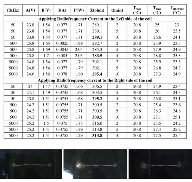
Afin de tester cette hypothèse, une première série d’expériences in vitro fut réalisée en appliquant un courant radiofréquence à une spirale plongée dans un gel électrolytique et en mesurant la distribution de température du gel à différents moments.
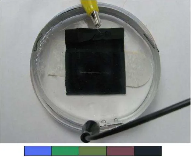
Le modèle se composait d'une spirale de platine placée dans une boîte de Pétri de 9 cm de diamètre, remplie d'un gel électrolytique de conductivité électrique similaire à celle des liquides organiques (0,67 S.m-1) et ayant une épaisseur de 3 mm.
Une bande métallique circulaire de 8 cm de diamètre fut placée dans la boîte de Pétri comme électrode de retour pour compléter le circuit. Un courant RF de différentes fréquences (50 à 5000 kHz) et différentes amplitudes (100 à 700 mV) fut appliqué à l’extrémité de la spirale.
Les tensions et la température ont été mesurées à l'aide d'un oscilloscope et d'un thermomètre, respectivement. Pour observer la distribution de température, une mince pellicule sensible à la température fut placée dans la boîte de Pétri.
Les résultats de ces expériences ont montré que la distribution de la température n’était pas modifiée lorsque la fréquence changeait.
Mesure de l’impédance des spirales
Pour poursuivre l’évaluation des effets inductifs et résistifs des spirales, les impédances résistives et inductives de différents types de spirales furent mesurées à différentes fréquences (50, 500 et 5000 kHz).
Les résultats de cette étude ont montré que l'impédance des différentes spirales reste presque constante malgré l'augmentation de la fréquence, mais que les impédances résistives de tous les types de spirales étaient beaucoup plus élevées que les impédances inductives.
Ce résultat indique que la baisse de la température qui a été précédemment observée sur toute la longueur de la spirale n'est pas due à des effets inductifs, mais est due à la baisse de potentiel produite par la résistance élevée de la spirale.
Ceci suggère également que le courant radiofréquence ne devrait pas être appliqué directement à une extrémité de la spirale, mais à un applicateur de faible résistance placé à l'intérieur de la spirale pour avoir une distribution plus homogène de la température.
Modélisation du potentiel et de la température par la méthode des éléments finis
Les distributions de courant et de potentiel ne dépendant pas de la fréquence, tel que déterminé précédemment, ces distributions peuvent être calculées en résolvant l’équation de Laplace.
xiii
Plusieurs modèles numériques de spirales et d’applicateurs incorporés dans des milieux conducteurs représentant le tissu cérébral furent ainsi créés à l’aide du logiciel COMSOL® Multiphysics 3.5a.
La méthode des éléments finis fut utilisée pour calculer d’abord la distribution du courant; par la suite, la densité de puissance dissipée par ce courant dans le tissu fut utilisée pour calculer l'évolution temporelle de la distribution de la température.
Modèle de spirale à résistance élevée
Le premier modèle consiste en une forme cylindrique mince de 2 cm de long représentant une spirale de platine de résistance élevée, immergée dans une autre forme cylindrique aplatie représentant la boîte de Pétri.
Ce modèle a confirmé les résultats des études préliminaires, soit que la température n'est pas répartie uniformément sur toute la longueur de la spirale et qu’elle est plus élevée au point d’entrée du courant, au début de la spirale.
Modèle d’applicateur à résistance faible : optimisation des dimensions
Le second modèle possède une géométrie de base semblable à celle du premier, sauf que la résistance du petit cylindre est beaucoup plus faible de façon à représenter un applicateur en acier plutôt qu’une spirale de platine de résistance élevée.
Après avoir montré que la puissance dissipée ne s’atténue pas le long de l’applicateur à cause de sa résistance faible, la géométrie de l’applicateur fut modifiée pour trouver la taille optimale pour produire une distribution de température uniforme. Les dimensions suivantes de l’applicateur furent étudiées, rayon : 100µm, 150 µm et 200 µm ; et longueur : 3 mm, 6 mm, 10 mm, 15 mm et 20 mm.
Les résultats ont montré que: la température maximum du tissu est plus élevée pour les applicateurs courts et minces; qu’une augmentation de température était observée aux deux extrémités des applicateurs longs ; et que pour produire une distribution de température uniforme, des applicateurs avec un rayon de 200 µm et une longueur comprise entre 6 mm et 10 mm étaient les plus appropriés.
Modèle d’applicateur inséré dans une spirale
Un troisième modèle constitué d’un applicateur d’acier semblable à celui du modèle précédent disposé dans l’axe d’un solénoïde de platine représentant une spirale endovasculaire fut construit pour étudier l'influence de la spirale de platine sur la distribution de température. La tension fut appliquée à une extrémité de l'applicateur et non pas à la spirale directement.
L’addition de la spirale de platine n’a produit qu’un très faible changement de la température maximale du tissu, et pratiquement aucun changement dans la distribution de température autour des spirales. Ces simulations démontrent l'efficacité de l'injection du courant radiofréquence à un applicateur en acier plutôt qu’à une spirale de platine.
Étude de validation de la résolution du maillage
Tous les modèles à éléments finis précédents furent également résolus avec un plus grand nombre d'éléments pour vérifier s'il y a un changement significatif dans les résultats. Le maillage fut ainsi affiné à quatre reprises pour le modèle d'applicateur en acier et le modèle d'applicateur au centre de la spirale de platine.
Il fut observé que pour les applicateurs très petits, des mailles plus fines mènent à un résultat plus précis et améliorent le résultat, mais que pour les applicateurs plus grands qui sont l’objet principal de notre étude, il n'a pas d'effets significatifs.
xv
Modèle d’applicateur inséré dans une spirale : expériences additionnelles
Pour valider certains des résultats de simulation par des expériences in vitro, un applicateur avec un diamètre de 0.46 mm fut placé dans la boîte de Pétri, et la distribution de température fut mesurée en appliquant un courant radiofréquence à 500 kHz pour des longueurs différentes de l'applicateur (3 mm, 6 mm, 10 mm, 15 mm et 20 mm).
De plus, pour confirmer les résultats en présence de la spirale de platine, l’expérience fut reprise en plaçant le même applicateur au centre d'une spirale de platine ayant les caractéristiques suivantes: longueur de 8 mm, rayon de 2mm, rayon de la section transversale de 0,19 mm. La longueur de l'applicateur en acier fut changée comme précédemment.
Puisque dans les modèles informatiques précédents le calibre de l'applicateur ne correspond pas à celui de cette dernière étude expérimentale, de nouveaux modèles numériques avec des dimensions et des caractéristiques identiques aux expériences furent créés.
Les résultats de ces expériences ont coïncidé avec ceux des simulations pour ce qui est de la forme des distributions de température, toutefois, les températures maximales mesurées étaient plus faibles que les températures simulées, peut être à cause de la taille du capteur de température et de l’effet de l’exposition à l‘air de la préparation expérimentale.
Modèle de volume conducteur semblable au cerveau
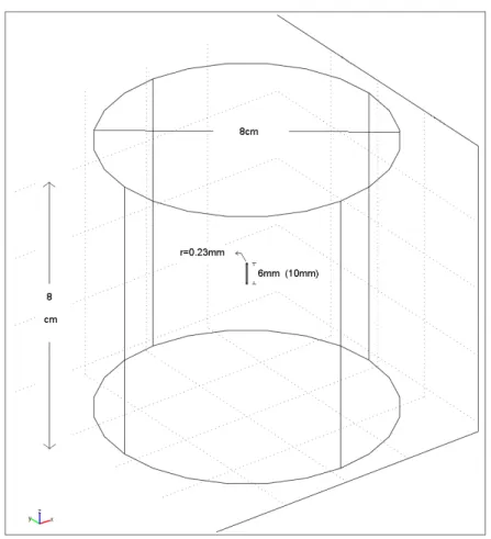
Des simulations furent effectuées dans un modèle présentant une géométrie plus proche de celle du cerveau. Ce modèle se compose d'un grand cylindre (avec un diamètre et une hauteur de 8 cm), représentant le cerveau et d’un petit cylindre au centre avec les caractéristiques de l'applicateur en acier.
Les simulations furent effectuées avec deux longueurs optimisées d’applicateur (6 mm et 10 mm) ayant un diamètre de 0.46 mm pour trouver les meilleures tensions et durées d'application et valider la sécurité de la méthode.
Des tensions différentes (5, 10, 15V) furent appliqués à une extrémité de l'applicateur durant 120 secondes et il a été constaté que pour minimiser les dommages aux tissus nerveux, nous devons prendre en compte la durée d'application et la tension.
Étude des effets de l’augmentation de la conductivité électrique due à la température
Finalement, comme la valeur de la conductivité électrique augmente légèrement avec la température (environ 2% par degré centigrade), le modèle numérique fut modifié pour tenir compte de cet effet et des simulations furent effectuées afin d’évaluer si la conductivité électrique peut être considérée comme constante (comme dans nos simulations précédentes), ou si sa variabilité en fonction de la température ne peut être négligée.
Cette étude a montré que pour des voltages faibles, où la température ne montre pas une grande élévation après 120 secondes, l'influence de la température sur conductivité électrique être négligée. Toutefois, pour des tensions de plus de 15 V, cet effet ne peut être ignoré et il doit être pris en compte.
Conclusion
En conclusion, nous suggérons que le courant de radiofréquence ne doit pas être injecté directement aux spirales de platine à cause de leur grande résistance électrique, mais qu'il doit être injecté dans un applicateur en acier placé au centre des spirales.
Aussi, un applicateur d'une longueur de 6 à 10 mm est approprié pour générer des distributions uniformes de température.
xvii
Enfin, des études animales devraient être réalisées afin d'étudier davantage cette approche prometteuse.
TABLE OF CONTENTS
ACKNOWLEDGMENTS ... III RÉSUMÉ ... IV ABSTRACT ... VI CONDENSÉ EN FRANÇAIS ... VIII TABLE OF CONTENTS ... XVIII LIST OF TABLES ... XXI LIST OF FIGURES ... XXII LIST OF ACRONYMS AND ABREVIATIONS ... XXVI
CHAPTER 1. INTRODUCTION ... 1
1.1 Cerebral Aneurysms ... 1
1.2 Causes, Developments and Risk Factors ... 3
1.3 Symptoms ... 4
1.4 Epidemiology ... 4
1.5 Treatments ... 5
1.6 Objectives ... 5
1.7 Thesis Outline ... 6
CHAPTER 2. LITERATURE SURVEY AND PRIOR RESULTS ... 7
2.1 Introduction ... 7
2.2 Surgical Treatment ... 7
2.2.1 Clipping ... 7
2.3 Minimally Invasive Treatments ... 9
2.3.1 Coiling ... 9
2.3.2 Coiling Method Follow-up Studies ... 11
2.3.3 Risks and problems ... 12
2.4 Clipping vs. Coiling ... 13
xix
2.5.1 Balloon Occlusion ... 13
2.5.2 Liquid Embolic agents ... 14
2.6 Prior Results ... 15
2.6.1 Previous attempts ... 15
2.6.2 In vivo Radiofrequency Current Experiments ... 16
2.6.3 In vitro Experiments ... 17
2.7 Summary and Conclusions ... 19
CHAPTER 3. INVESTIGATING THE EFFECTS OF FREQUENCY ... 20
3.1 Introduction ... 20
3.2 Tissue phantom and experimental setup ... 21
3.3 Effects of frequency on the temperature distributions ... 23
3.4 Investigating the impedance of a simple coil ... 25
3.5 Conclusion ... 27
CHAPTER 4. ELECTROTHERMAL MODELING ... 28
4.1 Introduction ... 28
4.2 Theoretical analysis ... 28
4.3 High resistance coil model ... 29
4.4 Low resistance applicator model ... 31
4.5 Applicator-in-coil model ... 32
4.6 Effects of Mesh Size on the Simulation Results ... 32
4.7 Additional simulations and experiments ... 33
4.8 Applicator-in-coil experiments and modeling ... 33
4.9 Applicator-in-brain model ... 34
4.10 Temperature dependant electrical conductivity ... 36
CHAPTER 5. MODELING AND EXPERIMENTAL RESULTS ... 37
5.1 Introduction ... 37
5.2 High Resistance Coil Simulations ... 37
5.4 Applicator and Coil Size Optimization ... 41
5.5 Applicator-in-Coil Simulations ... 45
5.6 Effects of Mesh Size ... 47
5.7 Additional Applicator Experiments and Simulations... 50
5.8 Applicator-in-Coil Experiments and Corresponding Simulations ... 54
5.9 Applicator-in-Brain Simulations ... 58
5.10 Temperature Dependant Electrical Conductivity ... 60
MAIN CONCLUSIONS ... 63
xxi
LIST OF TABLES
Table 3.1 Electrical and temperature values during RF power application ... 23
Table 3.2 Impedance and Resistance of different kind of coils at different frequencies ... 26
Table 4.1 Parameters and constants of the platinum coil model ... 29
Table 4.2 Parameters and constants of the stainless steel applicator model ... 31
Table 4.3 Parameters and constants of the Brain Model ... 35
Table 4.4 Parameters of Equation 4.4 ... 36
Table 5.1 Effects of the dimensions of the applicator on the maximum temperature. ... 43
Table 5.2 Effects of the dimensions of the applicator in a coil on the maximum temperature. ... 46
Table 5.3 Effects of mesh size on maximum temperature ... 47
Table 5.4 Electrical and temperatures measurements for different lengths of applicator ... 50
Table 5.5 Electrical and temperatures measurements for different lengths of an applicator placed in the middle of a coil. ... 54
LIST OF FIGURES
Figure 1.1 Location of the arteries likely to have aneurysm (Brisman, 2009) ... 2 Figure 1.2 Different types of aneurysm (Yale Medical Group, 2010) ... 3 Figure 2.1 Clipping (Yale Medical Group, 2010) ... 8 Figure 2.2 Coiling (Yale Medical Group, 2010) ... 9 Figure 2.3 Platinum coil configuration (White et al., 2008) ... 10 Figure 2.4 Localized lesion after RF transmission through a platinum coil imbedded in a chicken
breast (Jean Raymond et al., 2010) ... 18 Figure 2.5 Lesion obtained with RF probe (Jean Raymond et al., 2010) ... 19 Figure 3.1 Electrical Model of a Coil imbedded in a conductive tissue ... 20 Figure 3.2 Electrical set up ... 21 Figure 3.3 A coil immersed in the gel. The color bar shows the different colors of the temperature
sensitive film. From left to right, the colors range from highest to lowest temperature with a range of 5 degrees Celsius. ... 22 Figure 3.4 Temperature distribution after 2 minutes with RF applied to the left side of the coil,
from left to right: f = 50 kHz, 500 kHz, 5000 kHz ... 23 Figure 3.5 Temperature distribution after 5 minutes with RF applied to the left side of the coil,
from left to right: f = 50 kHz, 500 kHz, 5000 kHz ... 24 Figure 3.6 Temperature distribution after 10 minutes with RF applied to the left side of the coil,
from left to right: f=50kHz, 500kHz, 5000kHz ... 24 Figure 3.7 Temperature distribution after 2 minutes with RF applied to the right side of the coil,
from left to right: f=50kHz, 500kHz, 5000kHz ... 24 Figure 3.8 Temperature distribution after 5 minutes with RF applied to the right side of the coil,
from left to right: f = 50 kHz, 500 kHz, 5000 kHz ... 24 Figure 3.9 Temperature distribution after 10 minutes with RF applied to the right side of the coil,
from left to right: f = 50 kHz, 500 kHz, 5000 kHz ... 25 Figure 4.1 Geometry of the first model ... 30 Figure 4.2 Mesh created by COMSOL ... 30
xxiii
Figure 4.3 Model of a platinum coil which will be placed around the steel applicator ... 32 Figure 4.4 Model of a solenoidal platinum coil ... 34 Figure 4.5 Applicator-in-Brain Model ... 35 Figure 5.1 Voltage distribution in the high resistance coil model. ... 37 Figure 5.2 Steady state temperature distribution for the high resistance coil model. ... 38 Figure 5.3 Temperature vs time at different points in the high resistance coil model. The upper 4
curves (yellow, red, blue, purple) illustrate the temperature at 4 points in the vicinity of the current entry point. The 2 lowest curves (black, green) correspond to parts of the other end of the coil (black) and the periphery (green). ... 38 Figure 5.4 Voltage distribution for the low resistance applicator model. ... 40 Figure 5.5 Steady state temperature distribution for the low resistance applicator model. ... 40 Figure 5.6 Temperature vs. time at different points in the low resistance applicator model. The
upper curves illustrate the temperature at the vicinity of both ends of the applicator. The lowest curves correspond to the periphery. ... 41 Figure 5.7 L = 3mm, from left to right r = 100 µm, 150 µm, 200 µ m. ... 42 Figure 5.8 L = 6 mm, from left to right r = 100 µm, 150 µm, 200 µm. ... 42 Figure 5.9 L = 10 mm, from left to right r = 100 µm, 150 µm, 200 µ m. ... 42 Figure 5.10 L = 15 mm, from left to right r = 100 µm, 150 µm, 200 µm. ... 42 Figure 5.11 L = 20 mm, from left to right r = 100 µm, 150 µm, 200 µm. ... 43 Figure 5.12 L = 3 mm, From left to right, voltage and steady state temperature distributions for
the high resistance coil model. ... 44 Figure 5.13 L=10 mm, From left to right, voltage and steady state temperature distributions for
the high resistance coil model. ... 44 Figure 5.14 L= 20 mm, From left to right, voltage and steady state temperature distributions for
the high resistance coil model. ... 44 Figure 5.15 L = 3 mm, from left to right r = 100 µm, 150 µm, 200 µ m. ... 45 Figure 5.16 L = 6 mm, from left to right r = 100 µm, 150 µm, 200 µ m. ... 45 Figure 5.17 L = 10 mm, from left to right r = 100 µm, 150 µm, 200 µm. ... 45
Figure 5.18 L = 15 mm, from left to right r = 100 µm, 150 µm, 200 µm. ... 46 Figure 5.19 L = 20 mm, from left to right r = 100 µm, 150 µm, 200 µm. ... 46 Figure 5.20 Maximum temperatures for the four mesh sizes in the applicator model. ... 49 Figure 5.21 Maximum temperatures for the four mesh sizes in the applicator-in-coil model. ... 49 Figure 5.22 L = 3 mm, images taken after 2, 5, 10 minutes... 51 Figure 5.23 L = 6 mm, images taken after 2, 5, 10 minutes... 51 Figure 5.24 L = 10 mm, images taken after 2, 5, 10 minutes... 51 Figure 5.25 L = 15 mm, images taken after 2, 5, 10 minutes... 51 Figure 5.26 L = 20 mm, images taken after 2, 5, 10 minutes... 52 Figure 5.27 Applicator simulation results, L = 3 mm. ... 52 Figure 5.28 Applicator simulation results, L= 6 mm. ... 52 Figure 5.29 Applicator simulation results, L = 10 mm. ... 53 Figure 5.30 Applicator simulation results, L = 15 mm. ... 53 Figure 5.31 Applicator simulation results, L = 20 mm. ... 53 Figure 5.32 L = 3 mm, images taken after 2, 5 and 10 minutes of RF delivery ... 55 Figure 5.33 L = 6 mm, images taken after 2, 5 and 10 minutes of RF delivery ... 55 Figure 5.34 L = 10 mm, images taken after 2, 5 and 10 minutes of RF delivery ... 55 Figure 5.35 L = 15 mm, images taken after 2, 5 and 10 minutes of RF delivery ... 55 Figure 5.36 L = 20 mm, images taken after 2, 5 and 10 minutes of RF delivery ... 56 Figure 5.37 Applicator-in-coil simulations, L = 3 mm. ... 56 Figure 5.38 Applicator-in-coil simulations, L = 6 mm. ... 56 Figure 5.39 Applicator-in-coil simulations, L = 10 mm. ... 57 Figure 5.40 Applicator-in-coil simulations, L = 15 mm. ... 57 Figure 5.41 Applicator-in-coil simulations, L = 20 mm. ... 57 Figure 5.42 Brain model with 6 mm long applicator, voltage = 5 V. ... 58 Figure 5.43 Brain model with 6 mm long applicator, voltage = 10 V. ... 58 Figure 5.44 Brain model with 6 mm long applicator, voltage = 15 V. ... 59 Figure 5.45 Brain model with 10 mm long applicator, voltage = 5 V. ... 59
xxv
Figure 5.46 Brain model with 10 mm long applicator, voltage = 10 V. ... 59 Figure 5.47 Brain model with 10 mm long applicator, voltage = 15 V. ... 59 Figure 5.48 Temperature dependant brain model for a 6 mm long applicator at 5 V. ... 60 Figure 5.49 Temperature dependant brain model for a 6 mm long applicator at 10 V. ... 61 Figure 5.50 Temperature dependant brain model for a 6 mm long applicator at 15 V. ... 61 Figure 5.51 Temperature dependant brain model for a 10 mm long applicator at 5 V. ... 61 Figure 5.52 Temperature dependant brain model for a 10 mm long applicator at 10 V. ... 61 Figure 5.53 Temperature dependant brain model for a 10 mm long applicator at 15 V. ... 62
LIST OF ACRONYMS AND ABREVIATIONS
ANBD Aneurysmal neck-bridge deviceAVM Arteriovenous malformation BPM Bioabsorbable Polymeric Material EVAL Ethylene Vinyl Alcohol Copolymer EVT Endovascular treatment
GDC Guglielmi detachable coils
ISAT International subarachnoid aneurysm trial Lipiodol Iodized oil
NBCA N-butyl-2-cyanoacrylate PVA Polyvinyl Alcohol
RF Radiofrequency
RFA Radiofrequency ablation SAH Subarachnoid hemorrhage SMC Smooth muscle cells WSS Wall shear stress
1
CHAPTER 1.
INTRODUCTION
1.1
Cerebral Aneurysms
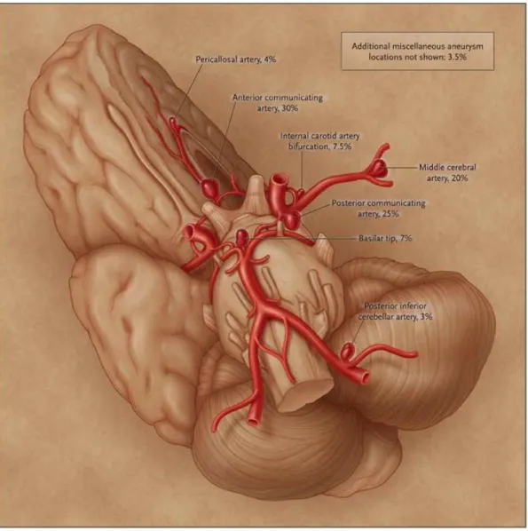
In general, arteries have three layers: the tunica externa (mainly composed of connective tissue), the tunica media (smooth muscle cells (SMCs), and elastin) and the tunica intima (endothelial cells; usually 1-3 layers of SMCs). The internal cavity, where blood flows, is called the lumen. The loss or absence of the muscular wall of the artery and of the elastin, which can occur in any blood vessel but more often in arteries than veins, will cause a weakening of the artery. This kind of structural effect may result in a ballooning or widening of the artery which is called a brain aneurysm, cerebral aneurysm, or intracranial aneurysm. Figure 1.1 shows the location of the arteries that are more likely to have aneurysms, along with their prevalence (as published by Brisman (2009)).
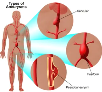
There are three types of cerebral aneurysm: saccular, fusiform, and dissecting. The saccular aneurysm, the most common type occurring in 90% of aneurysms, is a “berry” like aneurysm with a narrow stem (or neck). A fusiform aneurysm is a swelling on all sides and is associated with atherosclerosis. A dissecting aneurysm, a less common aneurysm, usually results from a small tear in the inner layer of the arterial wall, with blood entering and separating the structural layers of the artery (Brisman, 2009; Yale Medical Group, 2010). (Figure 1.2)
3
Figure 1.2 Different types of aneurysm (Yale Medical Group, 2010)
1.2
Causes, Developments and Risk Factors
Cerebral aneurysm may have a congenital cause or may be acquired. The frequent localization of saccular aneurysms in cerebral arteries, as compared to other systemic arteries, suggests that, some local factor is involved. Branching patterns may influence the formation of aneurysms. It has been shown that changes in the configuration of the bifurcation could alter blood flow patterns (N. Brown, 1991). Since cerebral aneurysms frequently occur at a vascular branching point or a curvature, its development may depend on various properties of blood flow. For instance hypertension and atherosclerosis can alter the blood flow and this may cause a weakness in the arterial wall (Shojima et al., 2005; Brisman, 2009). Flow may act through two directionally different forces. The first factor is the “impacting force”, acting perpendicular to the vessel wall. The other factor thought to have effects on the creation and development of cerebral aneurysms, is wall shear stress (WSS). WSS is a hemodynamic stress which acts parallel to the vessel wall and affects the cellular function of the endothelium (Shojima et al., 2005; Shojima et al., 2004).
Some congenital risk factors for cerebral aneurysms include arteriovenous malformation (AVM), coarctation of the aorta, polycystic kidney disease, Noonan’s syndrome (genetic disorder causing abnormal developments of parts of the body) and many others (Liebeskind, 2009; University of Virginia Health Center, 2007). A familial form may be present in 10% of cases.
Acquired risk factors can be age (>40), hypertension, atherosclerosis, smoking, illicit drug usage, trauma, and infection (Taylor et al., 1995; Brisman, 2009).
1.3
Symptoms
In many cases, cerebral aneurysms remain clinically silent and unruptured aneurysms are discovered during imaging for unrelated symptoms, although it is possible to list headache, dizziness, eye pain, and vision problems as symptoms associated with the discovery of unruptured aneurysms.
Most aneurysms are discovered at the time of ruptures that have caused subarachnoid hemorrhage (SAH) and in some cases stroke or death. The size and the location of the aneurysm have been reported as risk factors for hemorrhage (Murayama et al., 1999). When a blood vessel ruptures, bleeding normally occurs in the subarachnoid space but the brain will face severe problems. The tissues may not receive enough oxygen and nutrients. The resulting pressure will cause irritation and swelling. About 20% of strokes happen this way (Brisman, 2009). Some of the symptoms that can be listed include: severe headache, nausea and vomiting, stiff neck, hypertension, loss of balance, blurred vision, photophobia, irritability, and altered level of consciousness (including a deep coma) (Brisman, 2009; University of Virginia Health Center, 2007). Frequent symptoms such as headache, nausea, stiff neck may last for several days.
1.4
Epidemiology
Studies show that the prevalence of cerebral aneurysms in the adult population is between 1% and 5% (Wiebers et al., 2003). It mostly occurs in late 40s and early 60s (A Sadato et al., 1995; Brisman, 2009), and it is more common in women than men (Brisman, 2009). It has also been
5
estimated that the incidence of SAH from a ruptured aneurysm is approximately 1 case per 10,000 persons in the United States (Schievink, 1997).
1.5
Treatments
There are three main treatments for unruptured cerebral aneurysm: conservative management, surgery, and endovascular treatment (Brisman, 2009). Most clinicians believe ruptured aneurysms should be actively treated, because the risks of a second hemorrhage are so high. The chosen treatment depends on several factors such as: shape, size and location of the aneurysm, age, overall health and medical history, signs and symptoms, presence or absence of risk factors for aneurysm rupture, opinion and preference of the patient. These conditions can also affect the clinical outcome of the treatment (Murayama et al., 1999). There is still no evidence, however, that unruptured aneurysms must be treated.
Surgical treatment, which will be explained in next chapter, is the oldest reported method of treating cerebral aneurysms. However, it is now less in usage because of the emergence of new minimally invasive methods. The most popular endovascular treatment is coil embolization. An important drawback of the endovascular method is the occurrence of recurrences, in 10-30% of cases (Lozier et al., 2002). Therefore, research projects were designed to understand and hopefully minimize this problem. Although the exact mechanism involved in recurrences is unclear, one of the hypotheses is that recanalization originates from the endothelium and that endothelial denudation can prevent recanalization (Jean Raymond et al., 2004). The most recently proposed method to ablate the endothelial lining to prevent recurrences is radiofrequency ablation (RFA) which is still under investigation.
1.6
Objectives
In radiofrequency applications, it is possible to achieve different outcomes by varying energy output, time of application and configuration of the RF electrodes. For RF heating of coils, we wish to ablate the endothelial lining as completely as possible while limiting the risk of damage to surrounding tissues. The main objective of this study will be to investigate the effects of
radiofrequency delivery to the platinum coil (the coil which is placed in the aneurysm in the coil embolization procedure) on temperature and voltage distribution in the surrounding tissues. The reason for monitoring these effects is to optimize the parameters, minimize the risk of recurrences, and minimize the risks of adverse effects. We will consider the effects of following factors on the temperature distribution: coil size, the duration of applied current, the frequency, and the power. The proposed methods to investigate the influence of these specific factors are computer simulation and in vitro experiments. The finite element method is used to compute the current distribution in the tissues surrounding a simple coil; the dissipated power density is used to compute the temporal evolution of the temperature distribution. Temperature measurements performed in a similar tissue phantom are used to validate the model.
1.7
Thesis Outline
In Chapter 2, entitled Literature survey and prior results, a brief description of the treatment techniques, their advantages and failures are provided and then, the first attempts at applying RFA are explained. In Chapter 3 the effects of RF in this application is investigated. Chapter 4 will describe the details of the methods used in this study. In Chapter 5 results of the simulations and experiments are shown and discussed. The last chapter will conclude and provide suggestions for future research.
7
CHAPTER 2.
LITERATURE SURVEY AND PRIOR RESULTS
2.1
Introduction
Intracranial aneurysms (cerebral aneurysms or brain aneurysms) relate to a weakening of a brain artery which produces a ballooning of the wall of the artery. As the wall is weakened, it may rupture and lead to stroke or death. We can categorize treatments into two groups: surgical treatments and endovascular treatments (EVT). EVT are minimally invasive, such as coil embolization. In this chapter, the existing treatments, their advantages and drawbacks will be discussed and compared.
2.2
Surgical Treatment
2.2.1
Clipping
The first reported treatment for cerebral aneurysm is surgical clipping which was introduced in 1937 by Walter Dandy, a neurosurgeon at John Hopkins Hospital. Surgical clipping is an invasive method where surgeon will reach the brain by removing part of the skull. A metallic clip will be placed around the neck of the aneurysm, as shown in Figure 2.1, in order to prevent the blood flow from entering the aneurysm. Although surgical clipping is effective, some risk factors are associated with this method. The risk factors associated with this method are the size and location of the aneurysm and the general status of the patient (age, other diseases). According to a study done from 1976 to 1994 in Japan, among 173 patients with subarachnoid hemorrhages (SAH), 115 cases were treated and followed. The cumulative risk for SAH was 1.4% and 12.4% at 10 and 20 years respectively. This study clearly proved the long term efficacy of clipping but also showed that the risk is still present even 20 years after the treatment (Tsutsumi et al., 1999).
Figure
For evaluating the long-term survival of patients w
reported in 2001. This study was mainly about comparing patients with unruptured aneurysm who did and did not have a clipping. Observed patients were 4619 patients who were hospitalized from 1987 to 2001 because of cerebral aneurysm. The rates of 30
underwent surgical clipping with ruptured aneurysm were 13.4% while in the ones with unruptured aneurysm were 5.5%.
13.4% and 29% vs. 24% at 1, 5 and 10 years respectively
Their results showed that among patients with unruptured aneurysm who underw clipping, the rate of 30-day mortality w
undergo clipping. These rates at 1,
vs. 44.5%, respectively. Thus, survival estimates f significantly higher (P<0.001)
Figure 2.1 Clipping(Yale Medical Group, 2010)
term survival of patients who underwent clipping, a retrospective study is reported in 2001. This study was mainly about comparing patients with unruptured aneurysm who did and did not have a clipping. Observed patients were 4619 patients who were hospitalized use of cerebral aneurysm. The rates of 30-day mortality in patients who underwent surgical clipping with ruptured aneurysm were 13.4% while in the ones with
nruptured aneurysm were 5.5%. Follow-up study shows the rates of 17.9% . 24% at 1, 5 and 10 years respectively (Britz et al., 2004)
mong patients with unruptured aneurysm who underw
day mortality was 5.5%, while this rate was 7.9% in patients who did not hese rates at 1, 5 and 10 years were 8.5% vs. 16.8%, 13.4%
. 44.5%, respectively. Thus, survival estimates for the patients who had the clipping were igher (P<0.001) (Britz et al., 2004).
ho underwent clipping, a retrospective study is reported in 2001. This study was mainly about comparing patients with unruptured aneurysm who did and did not have a clipping. Observed patients were 4619 patients who were hospitalized day mortality in patients who underwent surgical clipping with ruptured aneurysm were 13.4% while in the ones with 17.9% vs. 8.5%, 22.4% vs. (Britz et al., 2004).
mong patients with unruptured aneurysm who underwent surgical in patients who did not . 16.8%, 13.4% vs. 30% and 24% or the patients who had the clipping were
There are multiple methodological flaws in this study
2.3
Minimally Invasive Treatments
2.3.1
Coiling
Coil embolization or endovascular coiling is t treat cerebral aneurysm. In this method catheter is guided through a blood vessel
catheter is placed inside the aneurysm with the help of
there, a thin platinum coil is advanced through the catheter into the aneurysm 2.2 (Yale Medical Group, 2010)
Figure
The platinum coil has a helical design with the configuration
dimensions of the coil vary according to the application and manufacture dimensions of D1, D2, and D3 varies between
to 20 mm, respectively (White et al., 2008)
gical flaws in this study however(Jean Raymond et al., 2005)
Invasive Treatments
Coil embolization or endovascular coiling is the most popular minimally invasive technique to In this method, instead of reaching aneurysm
blood vessel to reach the aneurysm from an artery in the groin. The the aneurysm with the help of fluoroscopic guidance
a thin platinum coil is advanced through the catheter into the aneurysm (Yale Medical Group, 2010).
Figure 2.2 Coiling (Yale Medical Group, 2010)
tinum coil has a helical design with the configuration presented in Figure 2.3. dimensions of the coil vary according to the application and manufacture
and D3 varies between 44.45 to 76.2 microns, 0.254 to (White et al., 2008).
9
(Jean Raymond et al., 2005).
he most popular minimally invasive technique to aneurysm through the skull, a from an artery in the groin. The fluoroscopic guidance and once it gets a thin platinum coil is advanced through the catheter into the aneurysm as shown in Figure
presented in Figure 2.3. The dimensions of the coil vary according to the application and manufacturers, the typical 0.254 to 0.381 mm, and 2
Figure 2.3 Platinum coil configuration (White et al., 2008)
The presence of the coil induces blood clotting, which results in an occlusion in the aneurysm and prevents rupture or re-bleeding. This technique was proposed in 1991 by Guido Guglielmi, a physician at UCLA. The coils are known as Guglielmi Detachable Coils (GDC). They are sometimes used in treatment of some tumors as well. In this application they are utilized to occlude the arteries feeding tumors (Guglielmi, 1998).
The occlusion method is based on two electrochemical principles: electrothrombosis and electrolysis. The cause of electrothrombosis is the negative charges of blood cells and proteins. Positive charges will attract these negative charges and make them form a clot (Guglielmi et al., 1991). The role of electrothrombosis has been clarified by Guglielmi et al. (1991). Their study showed that electrically charged coils will be covered by clot, a phenomenon that is not seen in noncharged coils. They also found that the deposition of blood cells on the coil increases with time (Zucchi et al., 2001). The other phenomenon, electrolysis, happens when a direct electrical current is applied to two immersed iron electrodes. Under these circumstances, the positive end dissolves and the negative one recruits the ferrous ions from the anode to the cathode. Since this phenomenon excludes noble metals, electrolysis will detach the platinum coil from the stainless steel delivery wire (Guglielmi et al., 1991). The detachment procedure will occur after several minutes of application of electrical current. The problem here is that if the number of coils increases, the duration of the procedure will increase as well as the risk of electrothrombosis (A
11
Sadato et al., 1995). To avoid these risks, another method for detaching the coils was introduced in 1995 by Sadato et al. In this method the coil is detached immediately after applying a monopolar high frequency current. A polyvinyl alcohol (PVA) rod is used at the junction of the coil and the delivery wire. By applying a high frequency electrical current, the heat produced by the current disrupts the PVA junction (A Sadato et al., 1995).
2.3.2
Coiling Method Follow-up Studies
So far, the coiling method has been described. As with any other treatment, some specific problems are associated with this method. The best way to investigate these problems is a follow-up study.
One retrospective study, which started after the introduction of GDC, showed that coil embolization is an effective method for patients suffering from ruptured posterior circulation aneurysms. Before that, treating the posterior circulation aneurysms was more difficult than for the ones located in other areas (Lempert et al., 2000). This study also showed the important role of GDC for patients in poor health condition. The majority of individuals in this study had saccular narrow neck aneurysms and most of the aneurysms were located at the basilar bifurcation. After treatment, recanalization was seen in 22.4% of patients. Most of the recanalization occurred in aneurysms with large neck size or in fusiform aneurysms (Lempert et al., 2000). Another follow-up study done at approximately the same period showed almost the same results and their authors suggested that long-term angiography should be used in order to find additional information (Ng et al., 2002). These studies showed good results for patients who are not good candidates for surgical clipping.
Reported series were thus far uncontrolled and the efficacy and benefit of coiling remained unproved.
Another study was done to investigate the effectiveness of endovascular treatments in conditions where clipping used to be preferred option. In this study, aneurysms located in the middle
cerebral artery (an artery closer to the surface of the surgical field) were treated with the use of GDC. The necks of aneurysms in this area usually are wide and they were considered less favorable for coiling. This study showed that, the mortality and morbidity rate for ruptured aneurysms were 6% and 1% respectively. The mortality and morbidity rate for unruptured aneurysms were 1% and 3% respectively. Recurrences were shown in 20% of patients. Thus, it was concluded that middle cerebral artery aneurysms can also be treated by coiling in most patients and that it is not subjected to neurologic deficits (Iijima et al., 2005).
Recurrences, the recanalization of the aneurysm, are considered more frequent after coiling than after clipping. A study was done amongst all patients treated in a hospital for ten years (Jean Raymond et al., 2003). In this study, recurrences were found in 33.6% of patients after one year. The important factors for the recurrences were listed as: aneurysm size, treatment of ruptured aneurysm, incomplete initial occlusions and duration of follow-up. Standhardt et al. also have done a study to evaluate the results of coiling treatment for unruptured intracranial aneurysms. According to their long term study, the occlusion rate depends on aneurysm size; for increasing aneurysm size, the proportion of completely occluded aneurysms decreased and complete occlusion was observed in 57.5% of cases. The value of this study was that it was done in patients with unruptured aneurysms (Standhardt et al., 2008).
2.3.3
Risks and problems
An important potential complication of EVT is perioperative aneurysmal hemorrhage. According to McDougall et al., the incidence of hemorrhage is low and even if hemorrhage happens, most of the patients will survive without serious problems. The possible factors of iatrogenic rupture may be excessive packing with coils, advancing the guidewire or the coil itself. To avoid rupture, it is important to be aware of the problem, decrease the catheter’s contact time and by not exerting forward pressure on the catheter before removing the guidewire (McDougall et al., 1998).
13
One of the problems occurring after the treatment is coil compaction. Researches were focused on this matter in 2001, Kawanabe et al. showed the relation between coil packing density and coil compaction (Kawanabe et al., 2001).
One of the other problems associated with the endovascular treatment discussed in follow-up studies, is that the occlusion may not be complete and it may result in recurrences. Some studies have been done to identify risk factors for recurrences. Raymond et al. did a research based on animal models showing that the type of aneurysm is an important factor which determines the degree of occlusion and the ones that are not coiled completely will recur more often (J. Raymond et al., 2008).
2.4
Clipping vs. Coiling
So far, the two main methods for treatment of cerebral aneurysms were discussed. Now reviewing the studies in which these treatments are compared might be useful.
International Subarachnoid Aneurysm Trial (ISAT) compared coiling and clipping in a large group of subjects: 2143 patients with ruptured intracranial aneurysms were followed for 6 to 14 years after treatment (Molyneux et al., 2009). The authors concluded that there was an increased risk of recurrent bleeding from coiled aneurysm compared with a clipped aneurysm, but the risks were small and that the risk of death at 5 years was significantly lower in the coiled group than it was in the clipped group. The risk factors for retreatment after 3 months of endovascular treatment are younger age, larger lumen size and incomplete occlusion (Campi et al., 2007).
2.5
Other endovascular treatments
2.5.1
Balloon Occlusion
One of the minimally invasive methods for treatment of cerebral aneurysm is balloon occlusion. This method, which was the first approach to embolization, was introduced by Fedor Serbinenko in 1971 (Linfante & Wakhloo, 2007). This method was helpful in treating the aneurysms that
were inappropriate for clipping because of their size and location (Añon et al., 1992; Ferrito et al., 1994; Meyers et al., 1999).
This method was abandoned after the introduction of GDC coils because it was less effective and more risky in most patients.
2.5.2
Liquid Embolic agents
In the cases where the neck of the aneurysm is too large or irregular, or the location of the aneurysm is not accessible, or performing a surgery can be difficult, parent artery occlusion is the solution, but it is not always possible because of the anatomical location. In such cases, Nishi et al. used an EVAL mixture (Ethylene Vinyl Alcohol Copolymer) as a liquid embolus. They first occluded the parent artery temporarily with a balloon catheter and then injected EVAL through a microcatheter located in the aneurysm (Nishi et al., 1996).
Aburano et al. also used another material when they could not reach the aneurysm. The material was a mixture of NBCA (N-butyl-2-cyanoacrylate) and Lipiodol (iodized oil) (Aburano et al., 2006). Though their aneurysms were on a bronchial artery, the material may be useful for the aneurysms in the brain.
More recently, Vanninen et al. introduced a new liquid embolic material called Onyx for peripheral interventions. It also can be used in combination with coils or balloon catheters. The problem with this material is that it is difficult to control (Vanninen & Manninen, 2007).
Interventions with materials such as balloons and microcoils can be accompanied with rupture or migration of the material to the main vessel, so they are not a good alternative to clipping. However GDC with its adaptability to the shape of aneurysm is a good option (Kawanabe et al., 2001).
15
2.6
Prior Results
2.6.1
Previous attempts
In order to solve the problems related to coiling, many studies have been done in this area. As it was mentioned earlier, recurrences and recanalization after coil embolization are the most important limitations of this treatment. Now, we will discuss some methods used in order to solve this problem.
Another concept to improve long term results of EVT was used by Murayama et al.: accelerating the “healing process”. They used Bioabsorbable Polymeric Material (BPM), which is a stimulator to inflammation in order to promote neointima formation, in addition to GDC. Although the results of long-term follow-up study are not available, the short-term animal based experiment showed good results (Murayama et al., 2002). Following this study, Taschner et al. did another study with the use of Matrix detachable coils (platinum coils covered with an absorbable copolymer) in order to assess its safety and stability after 6 months. They found that the stiffness of the Matrix coils makes the packing difficult. Their report showed that using the Matrix coils plus bare platinum coils result in stable outcomes (Taschner et al., 2005). Bendszus et al. used a new bioactive coil (Cerecyte) with polyglycolic acid loaded inside of the coil which did not affect the coil. They found that it was safe and potentially more efficient than bare coil, but their study needed to be verified by a prospective randomized trial (Bendszus et al., 2007).
In 2002, Raymond et al. suggested in situ beta radiation to inhibit the cellular process leading to recanalization. Their animal based study demonstrated that low-dose of beta radiation can prevent recanalization and it also showed improvement in short-term result of coil embolization (Jean Raymond et al., 2002). They also performed another study to find out the effects of coil properties and of the location of applied radiation. They concluded that coil properties can minimally affect the recanalization; however the necessary condition for the effectiveness of this process is thrombosis (Jean Raymond et al., 2003). They proved the feasibility of radioactive coils in a human experiment as well, though the long-term result of any damage to the nervous
system is unknown (Taschner et al., 2005). Based on subsequent animal studies, radiation did not show any harmful effects on nervous structure or on neointima formation. However, since clot organization will be influenced by high activities, fixing an upper limit for implanted radioactive is suggested (Jean Raymond, Metcalfe et al., 2006).
One of the hypotheses to be proved to prevent recanalization was endothelial denudation. Raymond et al. performed denudation by the means of an aneurysmal neck-bridge device (ANBD). ANBD is a mechanical device used in order to help placing and retaining the coils into the aneurysm. Though, it is hard to achieve complete denudation and it should be limited to the coiled lesion, endothelial denudation can inhibit recanalization. However, finding a better way rather than ANBD to perform the denudation process would be more convenient, since mechanical denudation is not practical in thin walled or ruptured aneurysms (Jean Raymond et al., 2004). They also suggested cryoablation of the endothelial lining as a substitute method for inhibiting recanalization. They found that cryotherapy can be helpful to some extent in preventing the recanalization, but there exist excessive nerve injuries in their cryotherapy procedure (Jean Raymond, Mounayer et al., 2006). Darsaut et al. assessed stenting combined with endothelial denudation and found that the stent alone cannot produce a solid form to occlude the aneurysm, however their combination will elevate the occlusion and lead to a better result (Tim Darsaut et al., 2007).
2.6.2
In vivo Radiofrequency Current Experiments
The latest attempt by Dr Raymond to improve the effectiveness of coil embolization is based on radiofrequency application (Jean Raymond et al., 2010). Radiofrequency current has lots of clinical applications to create targeted lesions, for example, it is widely used for catheter ablation of arrhythmogenic substrates in cardiology. In vivo studies were performed in order to show the effects of radiofrequency ablation (RFA) on recanalization. In this application, RFA was likely to denude endothelial layer while having minimum effects on surrounding nervous tissues. Two methods were compared; standard coil embolization and coil embolization followed by RFA of the endothelial lining. The coils (3 to 4 mm 0.015 platinum-tungsten coils 8 to 10 cm in length)
17
were placed in the arteries. The experiment was done in 6 dogs. In the cases with RFA, a 500 kilohertz (kHz) sinusoidal current with an output power of 20 to 30 W which was adjusted in order to keep the temperature constant at 60°C, was applied to a standard platinum coil for 60 seconds. The tissue surrounding the coil is heated by both resistive heating and conductive heating. Complete occlusion was shown after the procedure in both cases. After two weeks, the results of coil embolization with RF were compared with the results of coil embolization alone, these results suggested that RFA can be effective for both endothelial denudation and improvement of coil embolization, but there is a need to find optimal RFA parameters (power, duration, electrode size, etc.).
2.6.3
In vitro Experiments
A first set of in vitro experiments was done in order to show the power distribution along the coil. To perform this experiment, a coil (2-5mm caliber 0.015; 2 to 8 cm in length; Boston Scientific) connected to an RF generator (HAT 200, Osypka Company, Germany) was placed in a piece of chicken breast meat. An RF current at 10 watts with a 500 kHz frequency was applied to the coil for 60 seconds. As it is shown in Figure 2.4, the lesion (white) is limited to the first part of the coil. One of the possible causes of this effect may be related to the coil shape; as it was shown previously (Figure 2.3), the coil is rolled up on itself and forms a solenoid whose inductive impedance might oppose the passage of radiofrequency current.
Figure 2.4 Localized lesion after RF transmission through a platinum coil imbedded in a chicken breast (Jean Raymond et al., 2010)
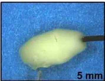
Another experiment was also done by applying a RF current through a stainless steel coil (homemade neurovascular probe) imbedded in an egg white solution. When the temperature reaches a critical value (about 60oC), the solution coagulates (Figure 2.5). The length, caliber and shape of the probe were investigated and it was found that for long probes, the lesion was not be continuous and that short probes had sudden impedance rises and peak temperature. It was found that by increasing the caliber, the lesion area was increased and that the shape of the probe affected the depth of the lesion. The best result is shown in Figure 2.5 where a homogenous lesion was produced.
To investigate the effects of the platinum coil, some preliminary experiments were performed by placing the probe in the middle of a standard platinum coil. This showed the feasibility of the approach and the need for further experiments.
19
Figure 2.5 Lesion obtained with RF probe (Jean Raymond et al., 2010)
2.7
Summary and Conclusions
This chapter reviewed the studies dealing with the treatment of cerebral aneurysms. Two main treatments were compared and their respective merits were discussed. To improve the coiling technique, radiofrequency ablation was proposed. Based on preliminary in vitro and in vivo studies which showed the feasibility of this approach, there is a need to further investigate the modalities of radiofrequency current delivery (electrode shape and position, power, duration). In the following chapter, we will thus investigate various parameters that may impact on the efficacy of radiofrequency ablation as applied to this practical problem.