HAL Id: hal-01827400
https://hal.archives-ouvertes.fr/hal-01827400
Submitted on 26 Feb 2021
HAL is a multi-disciplinary open access
archive for the deposit and dissemination of
sci-entific research documents, whether they are
pub-lished or not. The documents may come from
teaching and research institutions in France or
L’archive ouverte pluridisciplinaire HAL, est
destinée au dépôt et à la diffusion de documents
scientifiques de niveau recherche, publiés ou non,
émanant des établissements d’enseignement et de
recherche français ou étrangers, des laboratoires
Application Deployment Strategies for Spatial Isolation
on Many-Core Accelerators
Maria Méndez Real, Philipp Wehner, Vianney Lapotre, Diana Göhringer, Guy
Gogniat
To cite this version:
Maria Méndez Real, Philipp Wehner, Vianney Lapotre, Diana Göhringer, Guy Gogniat. Application
Deployment Strategies for Spatial Isolation on Many-Core Accelerators. ACM Transactions on
Em-bedded Computing Systems (TECS), ACM, 2018, 17 (2), pp.1 - 31. �10.1145/3168383�. �hal-01827400�
Application Deployment Strategies for Spatial Isolation
on Many-core Accelerators
Maria M ´endez Real, Univ. Bretagne-Sud, UMR 6285, Lab-STICC, F-56100 Lorient, France
Philipp Wehner, Ruhr-University Bochum, Germany
Vianney Lapotre, Univ. Bretagne-Sud, UMR 6285, Lab-STICC, F-56100 Lorient, France
Diana G ¨ohringer, Technische Universitatet Dresden, Germany
Guy Gogniat, Univ. Bretagne-Sud, UMR 6285, Lab-STICC, F-56100 Lorient, France
Current cache side-channel attacks (SCAs) countermeasures have not been designed for many-core architectures and need to be revisited in order to be practical for these new technologies. Spatial isolation of resources for sensitive applications has been proposed taking advantage of the large number of resources offered by these architectures. This solution avoids cache sharing with sensitive processes. Consequently, their cache activity cannot be monitored and cache SCA cannot be performed. This work focuses on the implementation of this technique in order to minimize the induced performance overhead. Different strategies for the management of isolated secure zones are implemented and compared.
CCS Concepts: •Security and privacy→ Domain-specific security and privacy architectures;
1. INTRODUCTION
Side-Channel Attacks (SCAs) [Ge et al. 2016] allow an attacker, which has no direct access to criti-cal data, to analyze indirect or side channel information during or after the execution of a sensitive application (e.g., a cryptographic algorithm) in order to deduce the sensitive application behavior or critical information such as a cryptographic key. Depending on the side channel information to exploit, the attacker may or may not require physical access to the system. We focus on logical cache-based SCAs which do not require any physical access and which see the memory cache as the source of leakage. The cache is indeed a resource that several concurrent processes, sensitive and potentially malicious, compete for. When shared with an adversary, this latter can extract some information about the victim’s activity that can be used to perform cryptanalysis. These attacks can be performed
at different granularities; within a single core when the victim and attacker processes ex-ecute on the same core and share the level 1 (L1) cache [Percival 2005] as well as across cores, when the victim and attacker applications execute on different cores but share the Last Level Cache (LLC). These attacks have been proved practical as well in a cloud environ-ment when the victim and the attacker applications execute on different Virtual Machines (VMs) logically isolated, since applications across VMs are still sharing the LLC [Yarom and Falkner 2014][Liu et al. 2015][Irazoqui et al. 2015]. These attacks can steal sensitive infor-mation from systems implementing logically isolated execution environments [Evtyushkin et al. 2016]. Recently, these attacks have been extended to multiprocessor and Network-on-Chip (NoC)-based systems [Irazoqui et al. 2016] [Reinbrecht et al. 2016b]. We focus on clustered
NoC-based multi and many-core architectures (Figure 1). In fact, these latter architectures have re-cently emerged as they provide massive parallelism and high performance allowing a wide number of applications, from different sources and with different levels of trust, to be executed in parallel sharing physical resources (computation, memory and communication infrastructure). One example
is the automotive field, in which the vehicle computer is indeed responsible for handling multimedia applications (user interface, car navigation, entertainment such as radio, In-ternet, etc.), safety-critical vehicle applications (airbag and braking system for instance), vehicle communication applications (in a connected car context), as well as vehicle and en-gine management applications. In this context, multi and many-core systems could cope with the performance requirements [Trung-Dung et al. 2016][Burgio et al. 2016]. However, the co-habitation of these different applications sharing physical resources, makes mandatory the integration of security mechanisms. In particular, sensitive processes sharing caches with
poten-tially malicious applications are vulnerable to logical cache-based SCAs and can be attacked. A large amount of works aiming at countering logical cache-based SCAs have been proposed (Section 2.2). However, most of them have not been designed for recently emerged many-core architectures. These solutions require to be evaluated and, or revisited in order to be practical and efficient on multi and many-core architectures.
L2 L2 L2 L2 L2 L2 L2 L2 L2 L2 L2 Trusted kernel L2 L2 L2 R R R R R R R R R R R R R R R R NI PE1 PE4 PE2 PE3 L1 L1 L1 L1 L2 Apps OS
Host machine Many-core accelerator
. . .
Memory Cluster
Fig. 1: Overview of the considered system
A countermeasure taking advantage of the large number of resources in many-core architectures has been proposed in [M´endez Real et al. 2016a]. The aim is to prevent cache sharing with a sensitive application by temporarily dedicating part of the physical resources in order to execute it within an isolated environment (secure zone). All the resources within the secure zone are dedicated to this single isolated application preventing it from cache sharing. Consequently, its cache activity cannot longer be monitored and cache-based SCAs cannot longer be performed. In the meanwhile, non-isolated applica-tions execute normally and still share resources.
This paper is an extension of [M´endez Real et al. 2016a]. It particularly focuses on its imple-mentation in order to study and reduce the induced performance overhead. In this work we ex-tend [M´endez Real et al. 2016a] with different deployment strategies for the dynamic creation, man-agement of the secure zones. These strategies are evaluated on a TSAR-like architecture [TSAR 2014] and are compared in terms of induced performance overhead according to several performance met-rics. Results show that hybrid strategies between completely static and dynamic secure zone size ap-proaches offer more flexibility and reduce the induced performance overhead on the total execution time compared to fully dynamic approaches.
The new contributions presented in this paper are:
— The implementation of a set of services on a manager kernel based on the ALMOS Operating System (OS) kernel [Almaless 2014] in order to dynamically control the deployment of applications.
— The extension of the manager kernel in order to integrate the secure-enable mechanisms proposed in [M´endez Real et al. 2016a] guaranteeing the physically isolated execution of each sensitive ap-plication.
— The proposal of different secure zones deployment strategies including a static and dynamic secure zone size, as well as hybrid deployment strategies targeting a minimum guaranteed performance and resources reservation.
— The implementation and evaluation of the proposed strategies on a TSAR like many-core architec-ture through virtual prototyping.
— The comparison of the gathered results regarding performance metrics including the total perfor-mance overhead, the perforperfor-mance overhead on the execution of both, spatially isolated and non-isolated applications, the resources utilization rate, the waiting time for each application to be mapped, the time spent on the Trusted Manager kernel services including the deployment strate-gies algorithms and resource allocation decisions.
— Finally, the comparison of the different deployment strategies according to the performance metric to be optimized and to the considered execution scenario.
The remainder of this paper is organized as follows: Section 2 presents some background on cache-based side-channel attacks and current countermeasures. Section 3 presents the targeted architecture and associated threat model, and further explains the spatial isolation countermeasure that we
con-sider in our work. In Section 4, different secure zone deployment and management strategies are explained and discussed. Then, Section 5 presents the baseline strategy as well as the implementa-tion of the proposed deployment strategies. Secimplementa-tion 6 presents the evaluaimplementa-tion environment and the evaluation setup for the validation of the proposed approaches. In Section 7, results for each proposed strategy are analyzed and compared regarding a set of performance metrics. Section 8 discusses the
presented work in terms of security, previous and future work. Finally, Section 9 draws some conclusions and presents some future work.
2. BACKGROUND
SCAs correspond to an important class of attacks on multitasks systems [Ge et al. 2016]. These attacks exploit the leakage of information during or after the execution of the sensitive process from different physical measurements in order to deduce important information about a critical process (e.g., a cryp-tographic algorithm) [Bl¨omer and Krummel 2007]. When the attacker has no physical access to the platform, analyzing neither the electromagnetic radiation nor the power consumption of the system is possible. However, when physical resources are shared between sensitive and malicious applications, logical SCAs based on the analysis of the execution time of certain operations or memory accesses, are still possible. Especially, cache-based SCAs represent a main threat when caches are shared. This section first introduces logical cache-based SCAs. Then, literature related work is presented.
2.1. Cache-based SCAs
Cache-based attacks may be sophisticated, but their underlying idea is relatively simple: an attacker observes cache-based side-channel information such as the victim’s execution time or memory accesses in order to gain information about the victim process sensitive data. Additionally, if the attacker can run code on the victim’s machine, as well as manipulate the state of the cache, he/she is able to gain extra information. By exploiting this knowledge, the attacker can retrieve confidential data of the critical program [Bl¨omer and Krummel 2007]. Among cache-based SCAs, one distinguishes time-driven (or timing) from access-driven attacks.
2.1.1. Time-driven attacks.These attacks exploit the vulnerability that, for some algorithms, the execu-tion time is directly related to sensitive data. Moreover, attackers can exploit the fact that the execuexecu-tion time of an application is influenced by the current state of the cache leading to potential leakage of information. There are two categories of time-driven attacks; passive and active. The main difference is the location of the attacker. A passive adversary does not have access to the victim’s machine and thus, cannot manipulate the state of the cache directly. Here, the attacker process triggers the sensi-tive application (e.g., an encryption algorithm) a certain number of times and measures the execution time. This latter is influenced by the state of the cache, which is itself influenced by each sensitive application execution. These attacks need more samples than active ones and often require statisti-cal methods in order to successfully retrieve the sensitive information. In [Bernstein 2005], a passive time-driven attack is remotely performed on AES algorithm. On the other hand, an active attacker has access and is able to run code on the victim’s machine. This allows him to directly manipulate and probe the state of the cache by filling it with its own data or by evicting some specific cache lines. Here, the attacker can trigger the sensitive application, manipulate the state of the cache and measure the execution time. This gives to the attacker additional cache information, compared to passive attacks, and leads to more efficient attacks. A well known technique is the EVICT+TIME [Osvik et al. 2006]. Authors perform an active timing attack on AES showing its efficiency compared to the passive attacks presented in [Bernstein 2005]. Finally, in [Bonneau and Mironov 2006], authors improve this
type of attacks by almost four orders of magnitude compared to [Bernstein 2005] by specif-ically focusing on individual cache collisions during encryption and by attacking the final round of AES encryption instead of the first one in previous work.
2.1.2. Access-driven attacks.Access-driven attacks rely on the fact the attacker has access to the vic-tim’s machine and that there is a shared cache between the attacker and the victim processes. These attacks exploit the vulnerability that, for some systems, some instructions are related to sensitive data. The principle is to deduce which cache lines the victim has accessed by directly manipulating and probing the shared cache and observing the memory access time. This additional information about the victim’s cache accesses makes these attacks more efficient than time-driven ones. PRIME+PROBE is a well known technique [Percival 2005]. Assume that an attacker manipulates the state of the shared
cache by accessing some specific memory addresses by filling the cache with its own data (PRIME). Then, the victim runs for a certain time and potentially changes the state of the cache. Finally, the attacker measures the time to access the same memory addresses again (PROBE). A short access time would indicate that the attacker’s data is still in the cache (a cache hit) and thus that the victim has not accessed this cache memory line. On the contrary, a large access time would indicate a cache miss which indicates that the victim has accessed the same cache memory line. By exploiting this tech-nique, the attacker infers information about the memory locations accessed by the victim, and thus the instructions and data that have been accessed. These attacks are possible both, among the same execution core and across-cores.
Among the same execution core: Initially, cache-based attacks were performed through L1 caches
in multithreaded system when two processes, an attacker and a victim one, are concurrently running on the same core and thus share the same L1 cache. In [Gullasch et al. 2011], authors implemented this technique against a 128-bit AES implementation of OpenSSL 0.9.8n on Linux.
Across-cores: The focus of cache-based attacks has shifted from first-level to shared Last-Level
Caches (LLC) [Liu et al. 2015] [Irazoqui et al. 2016] [Kayaalp et al. 2016], enabling to perform these attacks across cores. The FLUSH+RELOAD technique [Yarom and Falkner 2014] for instance, targets the LLC. Consequently, to launch this attack, the victim and the attacker programs do not need to ex-ecute on the same core. This attack extends the technique presented above [Gullasch et al. 2011] with adaptations for multi-core environments. Furthermore, the FLUSH+RELOAD attack is a variant of the PRIME+PROBE technique [Percival 2005] but relies on shared memory pages between the victim and the attacker. Here, the attacker exploits the inclusiveness property of Intel LLC; every data on lower caches is cached as well in the LLC. Consequently, the attacker can evict a specific cache line (e.g., through a specific assembly instruction such as cflush) from the LLC wich will in turn evict the line from all the lower level caches. A round of attack of the FLUSH+RELOAD [Yarom and Falkner 2014] technique consists of three phases: In the first phase, a monitored shared memory line is flushed from the cache hierarchy. During the second phase the attacker waits letting some time to the victim to execute and to potentially access the monitored cache line. Finally, in the third phase, the attacker reloads the monitored cache line measuring the time necessary to load it. If the victim accessed the cache line during the waiting phase, then the line will be accessible in the cache and the load time measured by the attacker will be short. On the other hand, if the victim did not access the line, when reloaded, the line will be fetched from the main memory and the measured access time will be sig-nificantly longer. In [Yarom and Falkner 2014], Yarom et al., present some implementations of this technique. However, attackers might request a significant number of reloads which can be detectable. A variant in order to prevent attackers from reloading, resulting in a faster attack, is to replace the reload phase by a second flush phase (FLUSH+FLUSH) [Gruss et al. 2016]. Across-cores access-driven attacks have been proven practical across VMs [Irazoqui et al. 2015]. Furthermore, in [Reinbrecht et al. 2016b], a PRIME+PROBE-based attack has been implemented on a NoC-based Multiprocessor System-on-Chip (MPSoC). While cache-based SCAs are often performed against cryptographic algo-rithms, techniques presented above are generic and can be used to eavesdrop other non-cryptographic applications in order to recover sensitive (e.g., personal) information. In [Gruss et al. 2016] for instance, authors use the FLUSH+RELOAD technique in on eavesdropping keystroke timings.
In this work we focus on active time-driven and access-driven SCAs. In the next subsection, existing countermeasures are presented.
2.2. Cache-based SCAs countermeasures
We distinguish three different categories according to their main goal.
2.2.1. Modifying the implementation or traces of critical processes.Application-specific countermeasures have been proposed in order to make sure that the leaked information by the critical applications implemen-tation is independent of secret data. Crane et al. [Crane et al. 2015], propose a technique to transform each program in order to make its trace unique offering probabilistic protection against cache-based SCAs. A countermeasure against access-driven attacks, is to modify the implementation of sensitive applications (i.e., cryptographic algorithms) in order to avoid any cache access preventing cache leak-age useful for access-based SCAs. Different implementations of some classic cryptographic algorithms have been proposed. In [Bl¨omer and Krummel 2007], authors focus on AES algorithm [Daemen and Rijmen 2002] and propose several implementations. Results show that this approach leads to less ef-ficient implementations in terms of execution time. Against time and access-driven SCAs, some works
propose to modify the critical applications implementation in order to make them constant-time, i.e. which do not branch on secrets and do not perform memory accesses that depend on secrets [Campo 2016]. In [Barthe et al. 2014], authors give a proof that constant-time programs do not leak confi-dential information through the cache. However, these solutions are application specific. Alternative approaches are presented below.
2.2.2. Disrupt the adversary measurements.A more flexible approach is to allow non constant-time im-plementations but to introduce some disruptions on the possible attacker measurements in order to prevent the extraction of sufficient useful information from caches. One approach is to completely flush all the caches at each context switch [Tromer and Osvik 2010]. In this way, cache line monitoring would be ineffective since the attacker will always observe that all lines are evicted from the cache. In [Guan-ciale et al. 2016], this approach is implemented in AES examples on one core execution. However, this approach introduces a significant performance overhead on the execution of all processes (untrusted but also trusted processes) due to the increased cache miss rate (up to one order of magnitude delay overhead). This overhead is added to the cost of the flushing itself.
At the cache-level, in [Wang and Lee 2007], authors propose to introduce some uncertainty on the behavior of the cache by randomly permuting cache lines or by randomizing the memory-to-cache mapping. At the NoC level, in [Sepulveda et al. 2015], authors introduce random delay on each memory and cache access.
However these solutions offer probabilistic protection only. Other solutions, providing strict isolation in order to avoid any interference between the attacker and victim processes, are presented below.
2.2.3. Avoiding cache sharing.Disabling caches seems a naive solution in order to counter cache-based SCAs. Indeed, blocking attackers to use the caches concurrently with sensitive processes would make caches invisible to them and consequently, cache-based attacks would be impossible. However, this countermeasure may entail great performance costs for applications not using the cache.
Another approach is to partition the physical resources, especially the cache. One solution is to exploit a partitioned cache against cache-based SCAs guaranteeing that a sensitive application does not share partitions in cache. This solution avoids cache interference. Partitions are mostly static [Page 2005] [Kim et al. 2012]. A variant of this approach introducing dynamism on a cloud environment is page coloring [Shi et al. 2011] [Raj et al. 2009] which aims at isolating VMs cache dependencies. In this manner, physical memory pages are partitioned among VMs in such a way that no VM shares cache lines with any other VM. Same than page coloring, specific memory lines can be locked in the cache in order to ensure that only a given sensitive application can evict these lines from the cache [Wang and Lee 2007].
Previous approaches have not been originally designed for emergent architectures such as many-core systems. These solutions need to be evaluated and, or revisited in order to be practical and efficient for these new technologies. In contrast, in [M´endez Real et al. 2016a], the spatial isolation has been proposed in order to thwart cache-based SCAs on multi and many-core systems. This solution takes advantage of the large number of resources available in these systems. The main idea is to temporary dedicate part of the physical resources (called secure zone) to a single sensitive application providing an isolated environment for its execution. This solution avoids any cache sharing with the critical application and ensure the non interference with any other applications. Consequently, the sensitive application’s cache activity cannot longer be monitored and cache-based SCAs cannot longer be per-formed. This countermeasure will be further explained in Section 3.4. In this work we focus on this last solution and especially on its implementation in order to minimize its performance degradation. 3. CONSIDERED SYSTEM
We consider a many-core accelerator and we focus on the evaluation of different application strate-gies for the implementation of the spatial isolation solution against cache-based SCAs proposed in [M´endez Real et al. 2016a]. In this section, the system and associated threat model are explained. 3.1. Many-core accelerator
The system considered in this work (Figure 1) is composed of a host machine and a clustered NoC-based many-core accelerator. The host machine runs an OS and executes a great number of applications in parallel. The host machine and the accelerator are connected via a local interface (e.g., a Peripheral Component Interconnect (PCI)). TSAR [TSAR 2014] architecture, Kalray’s Massively Parallel
Proces-Application Number of clusters Percentage of the App exec. time Applications sharing
(App) used by this App where clusters have been shared the cluster with
Application 1 5 clusters 1 cluster shared for 99.4% of the exec. time Application 2 Application 2 5 clusters 1 cluster shared for 74.6% of the exec. time Application 1 1 cluster shared for 99.9% of the exec. time Application 3 Application 3 5 clusters 1 cluster shared for 83.0% of the exec. time Application 2 1 cluster shared for 16.9% of the exec. time Application 4 1 cluster shared for 99.9% of the exec. time Application 5 Application 4 6 clusters 1 cluster shared for 75.6% of the exec. time Application 3 1 cluster shared for 37.1% of the exec. time Application 5 Application 5 8 clusters 1 cluster shared for 15.7% of the exec. time Application 3 1 cluster shared for 45.6% of the exec. time Application 4
Table I: Cache attacks vulnerability in baseline strategy with 77% average resources utilization rate sor Array (MPPA) [Kalray’s 2016], Mellanox’ TILE-Gx36 Gx36 2017] and TILE-Gx72 [TILE-Gx72 2017] processors, are some examples of many-core architectures.This work relies on the TSAR architecture [TSAR 2014] used as an accelerator. This latter is composed of clusters interconnected with a 2D-Mesh NoC. Each cluster is composed of 4 processing elements (PEs), a network interface and a L2 memory bank (here the L2 cache is the LLC). While L1 cache is private to each PE, L2 cache is shared among all clusters of the platform. Moreover, the physical address space of the main memory is statically partitioned into a fixed number of segments (equal to the number of clusters in the archi-tecture). Each segment is statically mapped on a L2 memory bank as shown in Figure 1. Consequently, each cluster L2 memory bank is in charge of one memory segment. The memory is then logically
shared among all the PEs but physically distributed. Indeed, L2 caches are instantiated close to the cluster’s cores. This particularity of the architecture that was initially designed in order to
al-low a locality aware deployment is suitable as well for the implementation of the spatial isolation. For this work we consider a monotask PE. This prevents to share L1 caches. However processes ex-ecuting on different processors still share the LLC. When launching an application through the host machine OS, the user specifies whether the application needs to be executed spatially isolated within a secure zone. The host machine is responsible for the launch and execution of applications. However, it can delegate part of the execution workload to the many-core accelerator. Moreover, depending on the user applications requirements, the host machine can request the accelerator manager to create a secure zone on the accelerator. On the accelerator side, a dedicated cluster allows the execution of the manager responsible for the dynamic deployment and execution of applications.
3.2. Case study cache-based attacks vulnerability
A study was conducted in order to evaluate the vulnerability to cache-based SCA of applications in a normal execution scenario on a many-core architecture. For this, a TSAR-like (Figure 1) [TSAR 2014] architecture and ALMOS OS [Almaless 2014] are considered. In this scenario, there is no security mechanism implemented. The architecture encompasses a 4×4 2D-mesh NoC connecting 16 clusters: 15 regular clusters encompassing 4 processors, and one manager dedicated cluster encompassing only one processor (61 processors in total). Table II summarizes the parameters of the architecture used for these experimentations. 5 concurrent matrix multiplication applications are considered.
Each executing a 256×256 matrix computations. Each application is composed of 17 parallel tasks. A master task creates the matrices, splits the computation load, creates 16 child tasks and sends to each the required data. Each child task makes its own computation and sends the results to the master task (see further details in Section 6.2.2). Tasks of each application
may be spread across several clusters and thus may use and share several cluster memory banks (one LLC memory bank per cluster) with other applications. Experiment results, summarized in Table I, present, for each application, the percentage of its execution time where the application shared LLC memory banks, as well as the number of different applications the banks have been shared with. These results highlight the time that each application is vulnerable to cache-based attacks as well as the potential attacker processes (applications sharing LLC memory banks with). It can be concluded that, in this scenario, where the average resources (computing and memory) utilization rate is 77%, resource sharing introduces an important vulnerability for each application (from 15.7% up to 99.9% of their execution time) that needs to be addressed.
(3,0) (2,0) (1,0) (0,0) (0,0) (0,1) Execution at t0 (0,2) (0,3) Trusted Manager Idle cluster Isolated application 1 Isolated application 2 Non-isolated applications (3,0) (2,0) (1,0) (0,0) (0,0) (0,1) Execution at t1 (0,2) (0,3) (3,0) (2,0) (1,0) (0,0) (0,0) (0,1) Execution at t2 (0,2) (0,3) (3,0) (2,0) (1,0) (0,0) (0,0) (0,1) Execution at t3 (0,2) (0,3)
Fig. 2: Principle of spatial isolation 3.3. Threat model
For this work, the physical platform is considered trusted and not physically accessible. Furthermore,
we consider that the attacker is able to know the code of sensitive applications running on the accelerator (e.g., cryptographic algorithm which code is public) and to trigger its execu-tion, but cannot access it during runtime nor modify it. Finally, this work focuses on cache-based
SCAs which do not require any physical access to the system. The manager on the accelerator executes the minimum services required to control the deployment and execution of the applications (Section 5). It is also responsible for the isolation mechanisms and secure zones deployment strategies. Hence, the software code running on the manager must be trusted (Trusted Manager). This work focuses on the dynamic application deployment, execution and resource management on the accelerator. Thus, we assume that:
— the manager on the accelerator is trusted (Trusted Manager) and the boot step is protected, — the communication between the host machine OS and the Trusted Manager is protected,
— the off-chip accesses to external memory and peripherals as well as the NoC communications are secured.
Moreover, in this work, application migration is not considered due to the induced complexity and cost. Indeed, migration would imply the secure remapping of the application and processor context switch as well as the memory remapping of the application data and instructions in order to leverage data locality. However, migration might be considered in the future in order to cope with problemat-ics such as dark silicon, component aging, faulty components, etc. Finally, sensitive and potentially malicious applications may run concurrently on the accelerator.
3.4. Spatial isolation of sensitive applications
In order to thwart cache-based SCAs, we consider the physical isolation of sensitive applications pro-posed in [M´endez Real et al. 2016a]. The aim is to prevent cache sharing for every critical application by temporarily dedicating physical resources (secure zone) for its execution. A secure zone, is composed of a number of clusters that are completely dedicated to a single sensitive application during its en-tire execution time. Secure zone clusters might be spatially contiguous in order to minimize
the NoC latency on the communication between tasks within an isolated application. Secure
zones are dynamically deployed, managed and released. In this way, cache sharing with an isolated application is avoided, and cache-based attacks are no longer possible against isolated applications. Moreover, several isolated applications can run simultaneously (Figure 2), each one within a separate secure zone. Finally, when an isolated application has been executed, memory within its secure zone is cleared in order to avoid any leakage of information. Figure 2 illustrates the principle of this technique for dynamic size secure zones. Different consecutive execution times are shown (t0 < t1 < t2). At t0, there is no load on the platform. Then, at t1, three different applications, including Isolated applica-tion 1 requiring to be spatially isolated, are deployed and start their execuapplica-tion. At that time, there
are enough available resources. Consequently, applications do not share resources and do not interfere with each other. Later, at t2, previous applications have extended on several clusters, secure zone 1 encompasses now two clusters which are dedicated and are not shared with any other application. Further, Isolated application 2 has been deployed and executes within a 4 clusters secure zone. Other isolated applications have been deployed as well. Due to the increasing load on the platform, non-isolated applications are obliged to share their resources with each other. Before deploying a sensitive application, a secure zone is created dedicating a certain number of clusters, depending on the chosen deployment strategy (see Section 4). The sensitive application executes within the secure zone. Every task created by an isolated task is mapped and executed within the secure zone. Depending on the deployment strategy, secure zone resources can be dynamically released. Once the isolated applica-tion finishes, its remaining secure zone resources are released and memory within the secure zone is cleared in order to avoid any leakage of information. At this stage, released resources are declared available again and can be used by other applications. In order to integrate the new services required to dynamically manage the secure zones, the kernel services are extended. Notice that in this ap-proach, the non-isolated applications still use and share caches with other untrusted applications.On the other hand, the dedication of secure zone clusters resources might introduce an under utilization of resources and thus a performance degradation. In this work, we focus on the implementation of this technique in order to minimize and handle the induced performance overhead.
4. DIFFERENT APPROACHES FOR THE DEPLOYMENT OF SECURE ZONES
To implement spatial isolation, the kernel executed by the Trusted Manager requires to be extended with new services responsible for the dynamic management of applications and secure zones.
4.1. Static approach
A naive approach is to create a secure zone of a static size in terms of clusters. It can be composed of all the needed resources in order to achieve the isolated application maximum parallelism. Or it can be restrained to a limited size. The secure zone size is assumed to be known (e.g., previously determined, specified by the user, or through application profiling). The secure zone is created and all the resources within it are dedicated before the first task of the application can start executing. The secure zone size being fixed, each new task within the application will need to be mapped on the secure zone resources. If the zone includes all the resources the isolated application needs, each time there is a new isolated application task, resources within its secure zone will be available and the task will be mapped without waiting for resources. Once all tasks of the isolated application are finished, all the secure zone resources are released and are declared available again. If there are not enough available resources to create a secure zone, another attempt will be made when a resource is released. Consequently, the application will wait for available resources. Figure 3 shows the flow of the secure zone creation for every deployment strategy, the dashed block corresponds to a secure zone creation algorithm (see Algorithms 1 and 2). Algorithm 1 is responsible for the creation of a fixed size secure zone. This algorithm is the base for every strategy presented below. Algorithm 1 explains the fixed size secure zone algorithm with the following notations (lists are spelled in upper-case letters while single elements and variables in lower-case letters):
— A: architecture,
— P : list of idle clusters in A,
— l: required size in terms of number of clusters for the secure zone, — E: list of secure zone clusters,
— c: an initial cluster from which the secure zone is created (white cluster in Figure 4),
— d: current depth of explored clusters starting from c. Depth d is ranged from 1 to l. Figure 4 shows
the cluster exploration space according to d, for l=3. Indeed, when d=1, only the initial cluster c is explored (white cluster in Figure 4). When d=2, the initial cluster c has been explored and its 4 direct neighbor clusters are explored (light gray clusters in Figure 4). Finally, when d=3, thus, d=l, (c and its 4 direct neighbor clusters have been explored) the neighbor clusters of the neighbor clusters of c are explored (dark gray clusters in Figure 4). In Figure 4, it can be seen that the solution, a zone of l contiguous clusters starting from
c, can exist only within the represented zone (when d is less or equal to l, see Algorithm 1,
line 33),
Application intended to be spatially isolated
Secure zone creation algorithm
Did the algo-rithm succeed?
Dedicate resources to this secure zone and deploy the application
Wait until resources are released
Isolated application deployed yes
no
Fig. 3: Creating a Secure Zone
c d d d d d+1 d+1 d+1 d+1 d+1 d+1 d+1 d+1 Initial cluster c V c V n Fig. 4: Exploration of clusters — c0: the first cluster in V c,
— sort(list): sort of clusters in a list by the distance between each cluster and the initial cluster c (in ascending order) and
— V n: list of clusters to explore at depth d+1 (dark gray clusters in Figure 4).
For performance reasons, deployment strategies are based on greedy algorithms aiming at finding a solution, in this case l idle contiguous clusters, as fast as possible and not necessarily at finding the global best solution. The algorithm receives as input the architecture state as well as the
required size of the secure zone (A, and l respectively in notations above). It gives as output, a list of l contiguous clusters starting from a given cluster initial cluster, c in Algorithm 1 if success (here E). On the contrary, if the algorithm does not succeed, then the output is a failure notification.
Considering that idle clusters are in list P , the algorithm considers each idle cluster as the initial cluster c (Algorithm 1, line 14), but stops as soon as it finds a solution. Starting from c, it tries to find enough idle contiguous clusters by selecting for each cluster in the secure zone, the idle neighbor cluster the closest one to the original cluster c. This, in order to minimize the communication cost between the father task, that will be mapped on the original cluster
c, and the children tasks created by the father task and mapped on the remaining clusters
within the secure zone.
First, the algorithm considers the first element in P list (Algorithm line 18), adds it to a list of currently considered clusters V n (line 19), and removes it from P (line 20) in order to prevent from considering the same cluster again. Clusters in V n are sorted in V c by their Manhattan distance to the original cluster c in an ascending order (line 22). The variable
d, indicating the current clusters exploration depth, is increased. The closest idle cluster to
c found (first element in V c), c0, is added to the list of secure zone clusters E (line 27) and
removed from V c (line 28). If the required size of E is reached, then the algorithm is finished and E is returned. Otherwise, if the clusters exploration depth has not reached l, then the
idle direct neighbor clusters of c0 in P are added to the currently considered clusters in V n
list and removed from P (lines 34, 35). This procedure is repeated until the list V n is empty. Indeed, an empty V n list indicates that there is no zone of l idle contiguous clusters starting
ALGORITHM 1: Creating a fixed size Secure Zone
1:Input:
2:l: size of E in terms of number of clusters
3:A: architecture
4:Output:
5:E: list of clusters in the Secure Zone if success,
6:FAILED: if failure
7:Let be:
8:P : list of idle clusters in A
9:V c: list of clusters from P to explore at depth d
10:V n: list of clusters from P to explore at depth d + 1
11:d: current depth 12:c, c’: clusters in P 13: 14:while P 6= [] do 15: d := 0 16: V c := [] 17: E := []
18: let c being the first cluster in P
19: V n := [c]
20: remove c from P
21: while V n 6= [] do
22: V c := sort(V n), Vn is sorted by the distance from c in ascending order
23: V n = []
24: d = d + 1
25: while V c 6= [] do
26: let c’ be the first cluster of V c
27: add c’ to E
28: remove c’ from V c
29: if size(E) = l then 30: return E 31: end if
32: for all v a neighbor cluster of c’ in P do 33: if d<l then 34: remove v from P 35: add v to V n 36: end if 37: end for 38: end while 39: end while 40:end while 41:return FAILED
from c in the architecture A. In this case, a different initial cluster c is selected in P . If every cluster in P has been considered as initial cluster, then, there is no secure zone of l idle contiguous clusters. In this case the algorithm returns a failure notification.
— Advantages: In this approach, the size of the secure zone, in terms of clusters, is
deter-mined before its deployment. The amount of resources that the secure zone will include, will determine the parallelism that the isolated application will be able to achieve. There-fore, the performance of the isolated application can be favored by selecting a suitable secure zone size. The application will indeed be able to achieve its maximum parallelism if the secure zone is composed of all the resources needed by the isolated application.
— Drawbacks: On the other hand, before the isolated application can be deployed, it will
wait until the necessary contiguous clusters are available in order to create its secure zone. Thus, we can expect an extra waiting time before the execution of isolated applications that
will depend on the load of the accelerator and size of its secure zones. Moreover, since the resources within the secure zone are dedicated to a single sensitive application during the application entire execution time, an under-utilization of resources within the secure zone is expected. In the same
way, the untrusted applications are prevented to use the dedicated resources, which will impact their performance as well as the global performance (i.e., execution time of the set of applications running on the accelerator) due to the potential under-utilization of resources within the secure zones.
4.2. Dynamic approach
In order to cope with the under-utilization of resources within secure zones, three approaches involving a dynamic secure zone size have been considered.
ALGORITHM 2: Creating a dynamic size Secure Zone
1:Input: 2:A: architecture
3:Output:
4:E: list of clusters in the Secure Zone if success,
5:FAILED: if failure 6:Let be: 7:c: cluster in A 8: 9:E := [] 10:for all c ∈ A do 11: add c to E if c is idle 12: return E 13:end for 14:return FAILED
ALGORITHM 3: Extending a dynamic size Secure Zone
1:Input:
2:E: list of clusters in the Secure Zone,
3:A: architecture
4:c: original cluster on which the father task is mapped
5:Output:
6:E: list of clusters in the Secure Zone if success,
7:FAILED: if failure
8:Let be:
9:P : list of idle clusters in A
10:V c: list of clusters from P
11:V n: list of clusters from V c
12:c0: a cluster in E 13:c00a cluster in V c 14: 15:for all c0∈ E do 16: V c := [] 17: V n := []
18: for all v a non explored neighbor cluster of c0in P do
19: add v to V n
20: end for 21: if V n 6= [] then
22: V c := sort(V n), V n is sorted by the distance from c in ascending order
23: let c00be the first cluster of V c 24: add c00to E
25: return E 26: end if 27:end for 28:return FAILED
4.2.1. Fully dynamic approach.In this fully dynamic approach, the size of the secure zone is dynamically adapted to the needs of the isolated application according to the load of the platform. For this, the isolated application requires only one single idle cluster to form its initial secure zone (see Algorithm 2), and physical clusters are dynamically added (Algorithm 3) and released from the secure zone. When a new task belonging to an isolated application requires to be mapped, the dynamic approach algorithm first searches for an idle processor within the secure zone. If there is no idle processor within the secure zone, then it searches for an idle cluster contiguous to clusters within the secure zone. If no contiguous cluster is available, then, there are two possibilities, either the new task waits until a resource within the isolated application secure zone is released, or the task waits until a resource on the architecture is released and the secure kernel adds it to its secure zone.
— Advantages: Isolated applications might wait a shorter time than in a static size approach since an isolated application only needs one single cluster to start executing. Moreover, since the size of a secure zone is dynamically adapted, a better utilization of resources is expected. Consequently, the performance of untrusted applications may be less penalized.
— Drawbacks: While this approach might entail better resources utilization and less impact on the untrusted applications performance, isolated applications performance will no longer be a priority. Consequently, we can expect that increasing the secure zones size will be more difficult.
4.2.2. Hybrid approach.A variant of the fully dynamic approach explained above, is to dedicate a non-optimized number of clusters (specified by the user, parameter l in Algorithm 1) to an isolated appli-cation before executing it, but to dynamically add resources to the secure while needed (following the approach presented in Algorithm 3). In this approach the isolated application needs to wait until the secure kernel finds the minimum number of clusters required to form a secure zone before starting its execution. Once the secure zone is created and the secure kernel launches the execution of the isolated application, clusters can be dynamically added and released, but the minimum specified secure zone size is always guaranteed.
— Advantages: This solution guarantees a minimum size of the secure zone, and by consequence, a minimum performance of the isolated application. On the other hand, it also takes into account the current load of the accelerator when trying to dedicate more resources to the secure zone. Resources utilization rate is thus expected to be better than in a static approach thanks to dynamism. More-over, untrusted applications are expected to be less penalized than in the static secure zone size scenario since less resources are expected to be dedicated.
— Drawbacks: However, this solution may penalize the isolated applications performance since achieving their maximum parallelism is not guaranteed. Finally, this solution requires fixing a minimum secure zone size for each isolated application.
4.2.3. Resource reservation.An approach in order to favor the dynamic extension of secure zones when there are not enough available resources to create a secure zone of a suitable size (e.g., encompassing all the resources the isolated application needs), is to reserve currently non-available resources, in order to prevent other applications from using them once they are declared completely available again. Indeed, when an application intended to be isolated is ready to be mapped and there are not enough available resources to create an optimal size
secure zone (referred to as l), the largest available zone is chosen (of size l0) and dedicated to
the isolated application which immediately starts its execution. Further, the number of miss-ing clusters on the secure zone (l-l’) are selected among contiguous clusters to be reserved. These latter need to be contiguous to clusters within the secure zone or if necessary, to the reserved clusters. Reserved clusters are tagged and when a resource within them is avail-able, it will not be allocated to any other (trusted or untrusted) application. Once all the resources within a reserved cluster are declared available, the kernel adds it to the secure zone if the isolated application still needs it. Moreover, the secure kernel will constantly up-date the number of required clusters by the isolated application. In the meanwhile, if there are not sufficient clusters within the secure zone, isolated application tasks will need to wait for computing resources in its secure zone to be released. In this case, less reserved clus-ters would be necessary. Consequently, the secure kernel may dynamically release reserved clusters. As in this work application migration is not considered (see Section 3.3), once an isolated application starts to be executed, it cannot be migrated when a larger zone than its current secure zone is released. More sophisticated parameters can be used in order to decide
which clusters are worthy to reserve. Indeed, the execution time left for processors in each cluster or the number of pending tasks could also be taken into account when selecting clusters to reserve. While this would entail higher and more complex activity on the secure kernel, it would certainly increase the chances of extending the secure zones.
— Advantages: In case of a good bet, this solution can be very interesting as isolated applications only need one single cluster to start to be executed and reserved clusters allow achieving a good perfor-mance of isolated applications. Furthermore, the dynamism of the approach entails good resources utilization rates.
— Drawbacks: On the other hand, if the bet turns out to be bad, this approach can be very penalizing for isolated applications. In fact, if the reserved resources are not released during the execution of the isolated application, then, the secure zone will not be extended and new tasks within this application will wait for other tasks within the secure zone to finish in order to start its execution. Consequently, the isolated application may not achieve its maximum performance depending on the load of the accelerator and on the quality of the bet. Moreover, this approach requires a high activity on the trusted kernel compared with a static approach.
(3,0) (2,0) (1,0) Trusted Manager (0,0) (0,0) (0,1) (0,2) (0,3)
Physical architecture (Level 0 clusters)
Level 2
Level 1
Level 0
(0,0) (0,1) (1,0) (1,1) (0,2) (0,3) (1,2) (1,3) (2,0) (2,1) (3,0) (3,1) (2,2) (0,3) (3,2) (3,3)
Associated monitoring structure
A cluster structure Ch0 Ch1 Ch2 Ch3 Total M M M M M R R R R R P P P P P T T T T T
Chx: Child cluster number x M: Memory utilization R: Computing resources utilization rate P: Number of active processors = number of active tasks
T: Secure tag and secure zone identifier
Fig. 5: Overview of the monitoring structure
5. IMPLEMENTATION: BASELINE STRATEGY AND ITS EXTENSION
The services responsible for the dynamic allocation and management of resources on the accelerator (kernel services) are executed on a dedicated processor called manager. In their original state, they do not encompass any security mechanism and have been designed to favor performance based on the implementation of the ALMOS OS [Almaless 2014] (baseline strategy). These services have been extended in order to integrate the spatial isolation mechanisms proposed in this work. In this section, key kernel services are explained in their original and extended versions.
5.1. Monitoring
The state of the accelerator needs to be constantly monitored in order to dynamically make decisions on the resource allocation. For performance purposes, as in [Almaless 2014], a tree structure show-ing the state of each cluster has been implemented. Figure 5 shows an overview of the monitorshow-ing structure for a 16 clusters architecture, each cluster encompassing 4 processors. In this tree structure, physical clusters (level 0 clusters) are grouped by 4 forming a logical cluster (level 1). In the same way, logical clusters are grouped by 4 forming an upper level logical cluster (level 2). Each physical or logical cluster is associated with a data structure (A cluster structure in Figure 5) containing some parameters describing the state of the resources (the processors and memory utilization rates as well as the number of active processors and tasks). For a physical cluster, the first 4 columns in its corre-sponding cluster structure concern the state of the memory and the computing resources within the physical cluster. The fifth column is the sum of the 4 first columns. On the other hand, for a logical cluster the first 4 columns concern the states of the 4 child clusters (lower level clusters). The fifth column concerns the sum of the first 4 columns. This organization has been designed for performance purposes as it allows, when visiting the structure from top to bottom, to bypass clusters that do not provide enough resources for the current request. Moreover, it allows a bottom-up approach as well, in order to locally find available resources from a given physical cluster. While the shape and size of the monitoring structure are static, the parameters within the cluster structures describing the state of the accelerator are regularly updated. Two monitoring updates are implemented. First, a systematic one is made when a task is mapped on a processor or when a processor is released. For this update, it is necessary to visit and update values of the concerned physical cluster(s) but also of each upper level parent (logical) cluster. Second, resources utilization rates are periodically updated. The monitoring structure is consulted each time a decision on resource allocation needs to be made.
Extension: The monitoring structure has been extended in order to associate to each cluster a
secure tag indicating if the cluster is dedicated to a secure zone as well as the secure zone identifier (T in Figure 5). In fifth column, this active tag would indicate that all child clusters are already dedicated to a secure zone. Secure tags and secure zone identifiers are taken into account when taking a resource allocation decision, since these clusters are not available to other applications while tagged secure.
5.2. Mapping new applications or new tasks
The new application and new task mapping services are described in this subsection. First, the algorithm responsible to map new applications aims at finding a good processor to map the new task. At most, this algorithm visits the entire monitoring structure. The structure browse starts from the highest level cluster (i.e., the root of the tree structure, level 2 in Fig-ure 5). The aim is to find an idle processor. For this, if according to the fifth column values there is at least one idle processor, the first 4 columns are visited until one idle processor is found. When it is the case, the child cluster containing the found idle processor is visited. The process is repeated until an idle processor is found on a physical cluster. If there is no idle processor on the entire platform, the task is added to the pending tasks list and it will wait for a processor to be released. Second, a task may ask for the mapping of child tasks. Parent and child tasks are expected to communicate together. In order to favor performance, the mapping algorithm aims at minimizing the communication costs. For this purpose, a child task must be mapped the closest possible to its parent task. Indeed, the task mapping algorithm searches for an idle processor starting from the physical cluster of the parent task (level 0 cluster). If no idle processor is found in this cluster, the algorithm goes up and searches on the logical cluster containing the parent physical cluster (level 1 cluster). The algorithm consults then the fifth column of the logical cluster structure and if there is at least one idle processor in one of the child clusters (level 0), it goes down to the found clus-ter. On the other hand, if there is no idle cluster, the algorithm goes up to the parent cluster (level 2 logical cluster). This process is repeated until either one idle processor is found, or the entire structure has been visited and no idle processor is found. In this last case, the task is added to the pending tasks list and it will wait for a processor to be released.
Extension:These two services have been extended considering that, when deploying a new
application or task, the Trusted Manager knows whether it is intended to be isolated. If the new application or task to be mapped does not require to be isolated, then the original mapping algorithm is used. However, resources within clusters tagged secure in the monitor-ing structure are considered temporarily not available for non-isolated applications. Con-sequently, the original service algorithm exploration zone might be reduced since clusters tagged secure are not visited. On the other hand, if the application or task requires to be iso-lated, then the Trusted Manager uses one of the new algorithms for the creation and manage-ment of a secure zone proposed in this work according to the considered strategy presented in Section 4.
5.3. Releasing secure clusters
When an isolated application is finished, all the clusters remaining within its secure zone are released. Additionally, in dynamic secure zone size approaches, clusters are dynamically released. When a cluster from a secure zone is released, different steps are taken. First, memory within the cluster as well as remanent information (buffers, registers, state of the caches) need to be cleared in order to avoid any leakage of information. Second, the cluster is declared available again. This latter step requires to modify the secure tag T in the monitoring structure (Figure 5), for the corresponding cluster structure. Finally, the monitoring structure is updated in order to propagate the new information.
The extension of the kernel services including the different strategies presented in Section 4 have been implemented and compared via a virtual prototyping environment.
6. EVALUATION ENVIRONMENT AND EXPERIMENTAL SETUP
In this section, the virtual prototyping tool used for these evaluations and the experimental setup are presented.
6.1. Evaluation environment
The extension of the kernel manager services including the proposed deployment strategies have been evaluated and compared through the MPSoCSim tool [Wehner et al. 2015]. MPSoCSim is based on the Open Virtual Platforms (OVP) technology [OVP 2017], coupled with SystemC models [SystemC 2017]. It allows the evaluation of clustered NoC-based multi- and many-core architectures [M´endez Real et al.
Processor parameters Chosen value
Cortex A9 ARM Frequency 667MHz MicroBlaze (MB) Frequency 100MHz
Nominal MIPS 100 Real flit time (ARM) 850ns
Real flit time (MB) 40ns
System memory parameters Chosen value
L1 cache size 64 KBytes LLC Size 3 MBytes
NoC parameters Chosen value
Network frequency 100MHz 2D Mesh network size 4×4 clusters Number of processors per regular cluster 4
Number of processors in total 60 MBs + 1 ARM Router clock delay pass through 1 cycle
Table II: System parameters used for the Sevaluations
Trusted Manager R R R R R R R R R R R R R R R R LM: Local memory SHMem: Shared memory Cluster NI PE1 PE2 PE3 PE4 LM1 LM2 LM3 LM4 SHMem
Fig. 6: Overview of the prototyped system
2016b]. MPSoCSim relies on a system level modeling SystemC NoC where each router is connected to a SystemC Transaction Level Modeling standard (TLM-2.0) Network Interface (NI) connected to a local group called cluster. Each cluster can encompass up to 4 OVP processor models, each one connected to its local memory and shared resources within the cluster such as shared memory and a NI.
6.2. Experimental setup
6.2.1. MPSoCSim setup.For the evaluation of the experimentations presented in this work, a 2D mesh 4×4 NoC-based system has been prototyped (Figure 6). The NoC is composed of 15 regular clusters of 4 processors each, and one cluster encompassing one single processor dedicated to the execution of the kernel manager services. The system encompasses 60 processors and 1 processor dedicated to the kernel manager services. Each processor is connected to a private and shared memory that emulate L1 and L2 memory banks respectively. Table II summarizes the system parameters used for the experimentations. Notice that the chosen NoC parameters are identical to those used for the validation of the MPSoCSim tool [Wehner et al. 2015] providing reliable results.
6.2.2. Execution scenario.In this subsection, the Trusted Manager, the evaluated applications and ex-ecution scenarios are presented.
— Many-core accelerator Trusted Manager:
For these experimentations, one processor is dedicated and acts as the Trusted Manager of the accelerator. It computes the decision algorithms for the dynamic deployment of the applications (see Section 5), as well as the services needed for creating and handling secure zones (Section 4). — Applications:
We consider that, when launching an application, the user specifies whether it requires to be iso-lated within a secure zone. Synthetic applications with a high degree of parallelism such as matrix multiplications are used. Each application corresponds to 256×256 matrix computations. A first task (master task), generates the matrices, splits the computation and dynamically sends the data to each mapped slave task. Slave tasks can be mapped on the cluster executing the master task or on distant clusters according to the load of the platform. Slave tasks access to the memory within their cluster, perform the corresponding computation and send back to the master task the gen-erated results.When a task is finished, its PE is released and the Trusted Manager flushes the corresponding memory partition. A 17 parallel tasks application allows the study of an unfavorable scenario for the considered system. Indeed, when the size of the secure zone is fixed to achieve the application maximum parallelism, or when there are sufficient available resources, the secure zone will be composed of 5 clusters out of 16 in this considered case. However, only 17 processors out of 20 will be used. In consequence, 3 out of 4 processors on the 5th cluster will not be used, which represents an unfavorable case for the considered architecture. Applications are duplicated in order to increase the workload on the accelerator. All the applications are supposed to be ready to exe-cute from the beginning of the execution scenario. However, a priority level is associated to each application (master task) to determine in which order the ready tasks are served. For these experi-mentations, 5 applications, each one composed of 17 parallel tasks, are concurrently executing. This is 85 concurrent tasks in total and an average resources utilization rate of 77% when there is no isolated application.
— Evaluated secure zone deployment and management strategies:
The deployment strategies explained in Section 4 have been evaluated and compared:
— baseline strategy This scenario corresponds to the minimum services presented in Section 5. It does not include any security mechanism and no application is isolated.
— Strategy A.1. Secure zones with a fixed size encompassing all the resources needed by the spa-tially isolated application in order to achieve its maximum parallelism. In the case considered in this work, the application parallelism is 17 tasks running in parallel and clusters are composed of 4 PEs. Consequently, the secure zone size in this case encompasses 5 clusters (20 dedicated PEs in total).
— Strategy A.2. Secure zones with a fixed restrained size limited to 4 clusters. — Strategy B.1. Fully dynamic approach.
— Strategy B.2. Hybrid approach. In this case we fixed the guaranteed minimum secure zone size to 2 clusters.
— Strategy B.3. Resource reservation. — Evaluated execution scenarios:
For the evaluation of the performance overhead induced by each proposed strategy, different execu-tion scenarios have been considered.
— Single zone, priority 1 scenario. One single application (out of 5) requires to be spatially isolated within a secure zone. In this first scenario, this application has the highest priority (1 out of 5, 1 being the highest and 5 the lowest priority). Consequently, when mapped, there
is no load on the platform. This is the best scenario for an isolated application since it will be mapped the first one, then when there is no load on the accelerator.
— Single zone priority 4 scenario. One single application needs to be isolated. However, unlike the previous scenario, this application has a medium priority (4 out of 5). This allows to take into account the load of the accelerator when trying to create the secure zone.
— Multiple zones, multiple priorities scenario. In this last scenario, the load of the accelera-tor, as well as the number of applications requiring to be isolated, are considered. In fact, 3 out of 5 applications, with priority levels of 1, 3 and 5 respectively, require to be spatially isolated. 7. RESULTS
In this section, results of each pair of deployment strategy and each execution scenario are presented. Then, results are summarized and strategies are compared according to several performance metrics. 7.1. Results organization
Applications introduced in Section 6.2.2 are first run concurrently without any secure-enable mecha-nism (baseline strategy). Then, applications are concurrently run according to each pair of secure zone
deployment strategy, and execution scenario. Finally, since approaches are deterministic, experiments are run once. The main objective is to compare the different deployment strategies for the implemen-tation of the spatial isolation in terms of induced performance overhead and to analyze them according to different performance metrics:
— total execution time for the set of applications,
— average execution time of spatially isolated applications, — average execution time of non-isolated applications, — average computing resources utilization rate,
— execution time spent on the kernel services impacted by the spatial isolation mechanisms, — average time the isolated applications wait before been mapped.
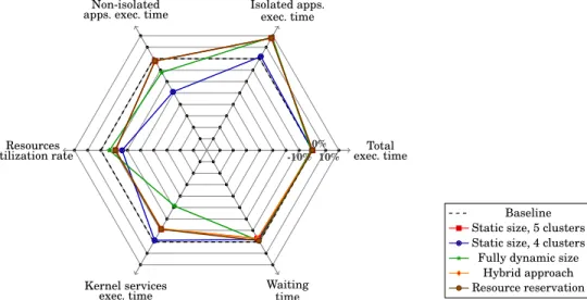
Apart from resources utilization rates in Table III, overhead results are presented in terms of percent-age compared to the baseline strategy. Results in Figures 7 to 11 and Table III allow the comparison of each performance metric for each pair of secure zone deployment strategy, and execution scenario (Section 7.2). Then, Figures 12 to 14 gather results of every performance metric classified by execution scenario.
7.2. Comparison according to each performance metric
First, notice that, execution scenario Single zone, priority 1 is particular. In fact, in this sce-nario, the application intended to be spatially isolated is served the first one since it has the highest priority. Consequently, when the manager deploys it there is no load on the accel-erator. As a result, strategies with a guaranteed minimum secure zone size (B.2.) and with resource reservation (B.3) give similar results than 5 cluster static secure zone size strategy A.1. Indeed, in B.2 strategy, only the kernel services execution time and total performance overhead are slightly different. Regarding B.3, it turns out to be identical than A.1 since the algorithm finds a secure zone encompassing all the resources needed by the application (5 clusters secure zone) directly without requiring to reserve any cluster. In this subsection, results for each performance metric are presented.
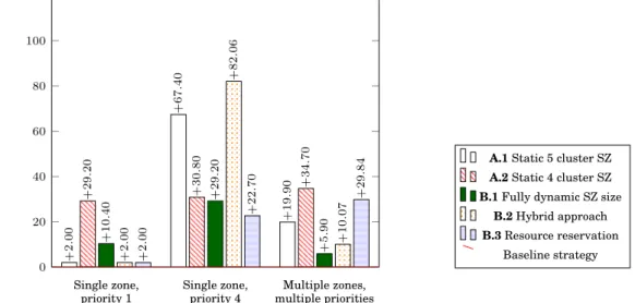
The total execution time overhead for each pair of secure zone deployment strategy, and execution scenario, is presented in Figure 7. While the dynamism in the considered scenarios makes it difficult to explain every aspect of the results, several observations can be made. First, according to these results, the static 5 clusters Secure Zone (SZ) (A.1. strategy) turns out to be the best solution in the evaluated scenarios providing the lowest overhead on the total execution time, almost negligible when there is no load on the accelerator (0.04%). While limiting the size of the SZ to 4 clusters (A.2.) entails a higher overhead than a 5 clusters SZ, the rest of the strategies does not seem to follow any trend but depend on the execution scenario. In order to better understand and compare these results, it is important to take into account that the total execution time is mostly impacted by both, the applications (isolated and non-isolated) execution time as well as the time spent on the Trusted Manager services for the ex-ecution of the deployment mechanisms. Finally, notice that applications and the Trusted Manager run in parallel. In order to compare the impact of different deployment strategies, the execution time
of both, isolated and non-isolated applications are highlighted in Figures 8 and 9 respectively. First, in Figure 8, it can be seen that in scenario Single zone, priority 1, results are neg-ative. As these results represent an overhead, negative ones indicate a better performance (reduced execution time) for isolated application(s) compared to the baseline strategy when the considered application was not isolated. This is explained by the exclusiveness of cluster resources and by the fact that, since the isolated application has the highest priority in this scenario, it is deployed the first one when there is no load on the platform. Indeed, contrary to the baseline strategy, isolated applications do not share cluster resources which avoids resource concurrency. Moreover, due to the highest priority of the isolated application, all the strategies, except for A.2., achieve the optimal size for the secure zone (5 clusters in this case), statically (i.e., A.1. strategy), or dynamically (B strategies). Consequently, the isolated application achieves its maximum parallelism which entails achieving better performance. In the A.2. strategy on the contrary, the size of the secure zone is fixed to a non-optimal size (4 clusters in this case), regardless of the fact that at the deployment time, all the resources are available on the accelerator. Furthermore, the static 5 cluster SZ strategy (A.1.) always achieves
Single zone, priority 1 Single zone, priority 4 Multiple zones, multiple priorities 0 10 20 30 40 +0 .04 +0 .32 +1 .31 +0 .32 +14 .10 +30 .74 +0 .99 +19 .22 +23 .85 +0 .06 +5 .17 +35 .86 +0 .04 +17 .97 +9 .02 Overhead on the total exec . time (%)
A.1 Static 5 cluster SZ A.2 Static 4 cluster SZ B.1 Fully dynamic SZ size
B.2 Hybrid approach B.3 Resource reservation
Baseline strategy (363.35 msec.)
Fig. 7: Total exe. time overhead (in %) compared to the baseline strategy
Single zone, priority 1 Single zone, priority 4 Multiple zones, multiple priorities −50 0 50 100 150 − 18 .00 +6 .00 − 10 .00 − 1 .90 +33 .40 +3 .70 − 20 .00 +98 .00 +86 .00 − 18 .00 +88 .00 +10 .00 − 18 .00 +105 .00 +8 .00 Overhead on the isolated application exec . time (%)
A.1 Static 5 cluster SZ A.2 Static 4 cluster SZ B.1 Fully dynamic SZ size
B.2 Hybrid approach B.3 Resource reservation
Baseline strategy (0.202 sec.)
Fig. 8: Overhead on the average exec. time of isolated applications, in % compared to the average application exec. time in the baseline strategy
when limiting the resources within the secure zone (A.2.) the performance of isolated applications is lower than in the first strategy for every scenario. However, limiting the secure zone size to 4 clus-ters (A.2.) instead of 5, further penalizes non-isolated applications execution time. This is because less resources are dedicated (only 4 clusters) and thus not available for non-isolated applications, but for a longer time. Indeed, in this case, isolated tasks need to wait for available resources within the se-cure zone, entailing longer execution time and thus longer resources dedication time. Furthermore, the fully dynamic strategy (B.1) and hybrid approach (B.2.) tend to penalize isolated over non-isolated applications. However, the hybrid approach guarantees a minimum number of resources for isolated applications so they can achieve better performance.
On the other hand, the time spent by the Trusted Manager kernel on the services impacted by the isolation mechanisms proposed in this work are presented in Figure 10. These services are:
mapping of each application and task (both, isolated and non-isolated), dynamic allocating and releasing resources, as well as creating, managing and releasing secure zones. Results are presented in terms of induced overhead in percentage of the time spent on the baseline

![Table I: Cache attacks vulnerability in baseline strategy with 77% average resources utilization rate sor Array (MPPA) [Kalray’s 2016], Mellanox’ TILE-Gx36 Gx36 2017] and TILE-Gx72 [TILE-Gx72 2017] processors, are some examples of many-core architectures.](https://thumb-eu.123doks.com/thumbv2/123doknet/11640058.307062/7.918.100.799.49.237/vulnerability-baseline-strategy-resources-utilization-mellanox-processors-architectures.webp)