I
Ministère de l'Enseignement Supérieur et de la Recherche Scientifique Université Ferhat Abbas Sétif 1
Institut d'Optique et de Mécanique de Précision
THESE DE DOCTORAT EN SCIENCES
Option :Optique et mécanique de précision Présentée par :
MR : BENTOUHAMI ABDERRAHMANE
Analyse expérimentale et numérique du comportement des structures
sandwiches à âmes en nids d’abeille soumises à l’impact
Experimental and numerical analysis of behavior of honeycomb sandwiches
panels subjected to impact.
Soutenue le: …/…/ …… Devant la commission d’examen:
Jury
Président BOUAOUADJA Nourdine Professeur Université Sétif 1 Directeur de thèse KESKES Boualem MCA Université Sétif1 Examinateurs : BOUSAID Ouzin MCA Université Annaba CHAOUI Kamel ProfesseurUniversité Annaba
II
بحلا لك مهبحأ نم ىلإ
ماطفلا هملؤي لفطلاو مهاوه عيضر انأ و
.يلإ هيف نوكي ام جوحأ تقو يف ثحبلا و رفسلا و ملعلا ةصرف يل حاتأو ينملعو ينهجو نم يبأ ىلإ
.مامتلإا و قيفوتلاب يل ءاعدلا اهلاح ناسل ناك يتلا يمأ ىلإ
ا ىلع امهرمع يف ليطي نأ ىلاعت و هناحبس الله لأسا
لعجي نأ و ةيفاعلا و ةحصلا امهعتمي نأ و ةعاطل
ضرعلا موي امهتانسح نازيم يف لمعلا اذه رجا بتكي نأ و ضرلأا و تاومسلا اهضرع ةنج امهتبقاع
.نيملاعلا يبر ىلع
III
First and foremost, I thank God through whom all things are possible.
I would like to express my deepest gratitude to my supervisor, Dr. KESKES BOUALEM, for his unwavering support and guidance throughout this research project. His patience, leadership, and never ending encouragement gave me the confidence to focus and proceed. I owe him an unbelievable amount of gratitude for his prominent role in helping me to achieve one of the greatest accomplishments in my life. His insight and generous support throughout
the various stages of this research work will always be appreciated.
Even, I would like to thank Dr. Keskes and the LMPA staff to accept me among them since 2009, I take here the opportunity to thank each member of LMPA with his name for the warm
welcome, kindness and help.
Special thanks go to Pr Crupi and Dr Epasto, whom provided great technical experience and guidance during my formation at Messina University in Italy.
I gladly extend my acknowledgments to Professor Bouaouadja Noureddine (Chair) again, Dr. Bousaid Ouzine (Examiner), Professor Chaoui Kamel (Examiner) in addition to their willingness to be members of my PhD dissertation committee, for their time, extreme
IV
complete this project without them, for their guidance, love and support throughout this long college career, I know it’s been tough, but we are finally through.
My thanks go also to my sisters Nadia and Amani.
From all my heart, I would like to thank my wife, Hayem, who enlightened my life with her love. Without her, I would not have been able to accomplish this work. I would like to thank her for believing in me and for all her support. For all her love, patience and dedication, I am truly grateful.I owe her an unbelievable amount of gratitude for her prominent role in helping
me to achieve one of the greatest accomplishments in my life.
For my little prince BAHAEDDINE
V
Experimental analysis and modeling of the buckling of loaded honeycomb sandwich composite.MTAEC 9, 49 (2), 2015
Meterials and Technology 49 (2015) 2, 235-242 2- Matériaux 2015 Mahdia (Tunisie), 22-26 Mars 2015 :
Study of honeycomb sandwich panel in low velocity impact.
3- Second International Workshop on Frature Mechanics FRACT’ 2 24-25 November 2013 Chlef, Alegria :
Communication 1:
Honeycomb sandwich panel under compression and three point bending loading tests.
Communication 2:
Experimental study of foamed sandwiches structures loaded in three point bending.
4- La 2eme journée des doctorants de l’IOMP le 29 mai 2013 :
Etude comparative du comportement en statique et en dynamique des structures sandwiches
5- Second Euro-Mediterranean Meeting on functionalized Materials EMM-FM 2013 Hammamet (Tunisie) March 24-28 ; 2013
Communication 1:
Mechanical behavior during compressive and numerical analysis of buckling of honeycomb composite.
Communication 2:
Experimental study and numerical modelling on three point bending test of honeycomb sandwich panels.
6- International Symposium of Aircraft Materials ACMA 2012 May 09-12, 2012 Fez, Morocco :
Experimental analysis and numerical modeling of buckling behavior on honeycomb sandwich panels under compression.
7- The International Congress for Applied Mechanics. La mécanique et les matériaux, moteurs du développement. JET 2012 Mai 02-04 mai, Marrakech-Morocco
Communication 1 :
Modélisation en flambement et étude du comportement en compression des structures sandwichs à âmes en nids abeilles.
VI d’abeilles.
8- Premier colloque national en aéronautique- first national congres on aeronautics CNA 2012 Mai2-3, Constantine- Algérie.
Communication 1 :
Analyse numérique et expérimentale du comportement en compression des structures sandwiches à âmes en nid d’abeilles.
Communication 2 :
Caractérisation des panneaux sandwichs à âmes en nid d’abeilles aluminium/aluminium.
9- 2eme Conférence Internationale sur les matériaux et les structures en composite , Novembre 28-30, 2011 ALGERIA, Oran
Communication 1 :
Modélisation en flambement et étude du comportement en compression des structures sandwiches à âmes en nid d’abeilles.
Communication 2 :
Modélisation numérique du comportement en flexion des panneaux à âmes en nid d’abeilles.
10- First international workshop on fracture mechanics FRACT’1 , 13-14 november 2011, Chlef, Alegria :
Experimental analysis and modelling of the buckling of loaded honeycomb sandwich panels.
VII
Acknowledgments ... III List of Symbols ... IX List of Figures ... XI List of Tables ... XIX
Chapter I: Introduction and Overview... 1
Chapter II: Literature Review... 8
II.1. Definition of composite sandwich panels ... 9
II.2. Advantages of Sandwich Composites ... 13
II.3. Application Areas of Sandwich Structures ... 14
II.4. Summary of Literature Review ... 16
II.5. Mechanical Properties and The theoretical models in literature ... 31
II.5.1. In-Plane Properties ... 31
II.5.2. Out-of-Plane Properties ... 34
II.5.3. The energy-balance model ... 39
II.5.4. Euler’s Buckling Analysis ... 41
II.5.5. The Johnson-Cook constitutive model [64] ... 43
Chapter III: Experimental Study ... 47
III.1. Materials ... 48
III.2. Experimental procedure ... 50
III.2.1. Low velocity impact tests ... 50
III.2.2. 3D Computed Tomography System (CT) ... 51
III.2.3. Quasi static indentation tests ... 56
III.2.4. Compression tests ... 57
III.3. Experimental Results, Analysis and Discussion ... 58
III.3.1. Low-velocity impact tests ... 58
III.3.1.1. Effect of impact energy on buckling behavior ... 58
III.3.1.2.Effect of cell diameter on the critical buckling load and deflection: ... 61
III.3.1.3.Effect of impact velocity on the critical buckling load and deflection ... 62
III.3.1.4. Effect of impact diameter on the critical buckling load and deflection (Wb).... 63
III.3.1.5. Effect of impact energy on deflection (Wb) of honeycomb sandwiches panels: 65 III.3.2.Tomography system results ... 66
III.3.3. Quasi-static indentation tests ... 82
III.3.3.1. Effect of indenter geometry ... 83
III.3.3.2. Effect of the cell size of honeycomb core ... 87
VIII
III.3.4. Compression tests: ... 93
III.3.4.1. Conclusions ... 99
CHAPTER IV: Theoretical Analysis of Buckling In Honeycomb Sandwiches under Different Loading Conditions ... 101
IV.1. Introduction ... 102
IV.2. Theoretical approach ... 103
IV.2.1. Theoretical approach for Compression loading ... 106
IV.2.1.1. Results ... 107
IV.2.2. Theoretical approach for Quasi-static indentation loading ... 108
IV.2.3.Theoretical approachfor Low-velocity impact loading ... 113
IV.2.3.1. Results ... 114
CHAPTER V: Finite Element Analysis and Results (Model of honeycomb panel subjected to Buckling). ... 118
V.1. Introduction ... 119
V.2. Development of FE Model ... 121
V.2.2. FEA model for quasi-static indentation and low velocity impact loading ... 126
V.2.2.1. Material and damage modeling ... 127
V.2.2.2. Contact and interactions ... 128
V.2.2.3. Mesh element ... 128
V.3. Results and discussion ... 129
V.3.1. Finite element compression results ... 129
V.3.2. Finite element Results and analysis for low velocity impact loading ... 134
V.3.3. Finite element results and analysis for quasi-static indentation loading ... 142
CHAPTER VI: ... 147
Comparison of Experimental, Theoretical and Finite element analysis Results (compressive, quasi-static indentation and low-velocity impact tests). ... 147
VI.1. Comparison of experimental, theoretical and finite element analysis results of honeycomb sandwich panel subjected to compression loading conditions ... 148
VI.2. Comparison of experimental, theoretical and finite element analysis results of honeycomb sandwich panel subjected to quasi-static indentation loading conditions ... 153
VI.3. Comparison of experimental, theoretical and finite element analysis results of honeycomb sandwich panel subjected to Low-velocity impact loading ... 156
CHAPTER VII: ... 163
CONCLUSIONS, RECOMMENDATIONS, AND FUTUREWORK ... 163
REFERENCES ... 166
Abstract ... 171
IX
Nomenclature
a length of panel (mm)
d diameter of the hemispherical indentor (mm) hc core thickness (mm)
m impact mass (kg) tf face thickness (mm) tc cell wall thickness (mm) v impact velocity (m/s)
w displacement perpendicular to the neutral face of cell wall (mm) wi impactor displacement (mm)
wb sandwich deflection (mm) Af failure area (mm2)
D flexural stiffness (Nmm) E Young’s modulus (MPa) Fc axial load per unit length (N)
Fexp experimental value of the buckling load (N) Fcbuckling critical buckling load (N)
Fwbuckling cells wall critical buckling load (N)
Fpbuckling honeycomb panel critical buckling load (N) Fcindbuckling indentation critical buckling load (N) FIshear critical shear load (N)
Fcimbuckling impact critical buckling load (N) Kc constraint factor
X α indentation depth (mm)
ν Poisson’s ration
cd dynamic crushing strength of the core material (MPa)
XI
figure 1.1: sandwich structure with honeycomb core. ... 2
figure 2.1: honeycomb sandwich structure. ... 9
figure 2.2: schematic diagram of hexagonal honeycomb. ... 10
figure 2.3: sandwich panels with (a) corrugated (b) foam and (c) honeycomb core. ... 11
figure 2.4: sandwich structure in comparison with an i-beam. ... 12
figure 2.5: mc laren mercedes slr bumper tube. ... 15
figure 2.6: over 50% composite commercial plane - boeing's 787 dreamliner. ... 16
figure 2.7: the graph shows the dependence of try on cell geometry. the solid line shows the prediction from the large-deformation model, and the dashed line shows the results from the small deformation model. the anisotropy ratio r = 0.58 (1 + sinα)/cosα [30]. ... 17
figure 2.8: typical strain curve obtained from the compressive test: (a) typical stress-strain curve, (b) schematic micro structural change during the compressive deformation of specimen [31]. ... 18
figure 2.9: variation of compressive strength of honeycomb composites with increasing temperature [31]. ... 18
figure 2.10: stages of quasi-static compression test of aluminum honeycomb: (a) initial state, (b) buckling initiation, (c) progressive folding and (d) densification [32]. ... 19
figure 2.11: stages of quasi-static compression of aluminum honeycomb at 30% and 60% compressive strain: (a) experiment, and fe analysis with (b) 2 mm, (c) 1 mm and (d) 0.5 mm element size. ... 20
figure 2.12: numerical (three different mesh sizes) and experimental load–displacement responses of aluminum honeycomb under compression. ... 21
figure 2.13: effect of cell size and cell wall thickness on crush response on aluminum honeycomb in compression. ... 21
figure 2.14: force–time histories with impact energy for the sandwich specimens. (a) body-shell sandwich panels (ge/ah) and (b) floor sandwich panels (al/ah) [33]. ... 22
figure 2.15: comparison of impact damage areas for floor sandwich panels (al/ah) after impact loading. (a) 1.57 j, (b) 3.04 j, (c) 4.49 j and (d) 5.93 j [33]. ... 23
figure 2.16: comparison of post-impact damage for sectioned sandwich panels after impact loading. (a) ge/ah specimens (4.13 j), (b) ge/ah specimens (6.00 j), (c) al/ah specimens (4.49 j) and (d) al/ah specimens (5.93 j) [33]. ... 23
XII
figure 2.18: impact tests performed; hc: honeycomb. grey indicates undamaged, black
indicates first panel damage noted [34]. ... 25
figure 2.19: damage observed after impact: honeycomb, 3m 18.8 kg [34] ... 26
figure 2.20: recorded data from tests versus impact energy. a) maximum loads (sum of four load cells) b) central displacements [34]. ... 26
figure 2.21: force–displacement curves of sandwich specimens under conical indenter [35]. 27 figure 2.22: effects of projectile nose shape on: (a) force–displacement curves and (b) energy absorption and energy-absorbing effectiveness (the error bars denote the standard deviations in replicate experiments) [35]. ... 27
figure 2.23: photographs showing typical deformation of (a) a monolithic plate (sample m1-2); (b) a honeycomb sandwich panel (sample b4); (c) an air sandwich panel (sample g6) [28]. ... 29
figure 2.24: four specimens showing core compression ratio reduces from the centre towards the edges of the sandwich panels. from top to bottom: samples a2, b2, c2 and d2 [28]. . 29
figure 2.25: permanent back-face deflection of honeycomb sandwich panels at various impulse levels [28]. ... 30
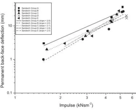
figure 2.26: the logelog graph of the permanent back-face deflection of honeycomb sandwich panels vs. impulse [28]. ... 31
figure 2.27: elastic deformation, (a) ‘w’ compression, (b) ‘l’ compression [15]. ... 32
figure 2.28: example of the variation between in-plane compression properties depending on sample size [62] ... 33
figure 2.29: comparison between theoretical size dependency influence on peak crushing strength and foam compression results [63]. ... 34
figure 2.30: deformed honeycomb due to out-of-plane compression loading [30] ... 34
figure 2.31: alexander's model: folding of thin walls in a cylinder [31] ... 35
figure 2.32: mcfarland model: ‘t’ direction crushing mechanism [32] ... 35
figure 2.33: shear flows in cell walls when honeycomb sample subjected to out-of plane shear stresses [22] ... 36
figure 2.34: spring-mass model for impact dynamics. ... 40
figure 3.1: illustration of honeycomb core material (ahs with d=6.4mm) by ct system. ... 48
figure 3.2: honeycomb core structure: (a) general view, (b) honeycomb unit cell, and (c) unit cell parameters. ... 48
XIII
figure 3.5: computerized tomography (ct) configuration. ... 52
figure 3.6: example of application on ct system. ... 52
figure 3.7: 3d computed tomograph system (y.ct vario machine). ... 53
figure 3.8: description of computed tomography system. ... 54
figure 3.9: ct analysis of an aluminum honeycomb core (ahs d=6.4mm). ... 55
figure 3.10: quasi-static experiment machine (zwick/roell). ... 56
figure 3.11: the different indenters’ geometry used in this study: (a) cylindrical, (b) conical, (c) truncated cone, (d) hemispherical 16mm and (e) hemispherical 20mm. ... 57
figure 3.12: experimental set up of the compressive test. ... 57
figure 3.13: load-displacement curves measured under impact loading (ahs d=3.2 mm). ... 59
figure 3.14: load-displacement curves measured under impact loading (ahs d=6.4 mm). ... 59
figure 3.15: load-displacement curves measured under impact loading (ahs d=19.2 mm) ... 59
figure 3.16: load-displacement curves measured under impact loading (nhs d=3.2 mm; di=20 mm). ... 60
figure 3.17: max load- impact energy for ahs d = 3.2 mm and ahs d = 6.4 mm. ... 60
figure 3.18: effect of impact energy on critical buckling load (nhs d = 3.2 mm). ... 61
figure 3.19: critical buckling load-deflection (w) for all used materials. ... 62
figure 3.20: effect of velocity and core cell size on impact critical buckling load... 63
figure 3.21: effect of impactor diameter on the impact critical buckling load (ahs d = 19.2 mm). ... 63
figure 3.22: effect of impactor diameter n the impact behavior (nhs d = 3.2 mm). ... 64
figure 3.23: effect of impactor diameter n the impact behavior (nhs d = 3.2 mm). ... 64
figure 3.24: effect of impactor diameter n the impact behavior (nhs d = 3.2 mm). ... 65
figure 3.25: effect of impact energy and impactor diameter on core deflection (buckling) (nhs d = 3.2 mm). ... 65
figure 3.26: comparison between experimental and ct results (ahs d = 3.2 mm) ... 66
figure 3.27: comparison between experimental and ct results (ahs d = 6.4 mm) ... 66
figure 3.28: effect of impact velocity on the middle plan core buckling (deflection) (comparison between ahs d = 3.2 and ahs d = 6.4 mm). ... 67
figure 3.29: the failure mode demonstrated by the ct image: (a) ahs d=3.2mm (v=3ms-1) and (b) ahs d=6.4mm (v=3ms-1). ... 68
XIV
figure 3.31: ct images of honeycomb panels after impact tests ahs 3.2 mm: (a) v = 1.5 m/s, (b)
v= 2 m/s and (c) v = 4m/s ... 71
figure 3.32: ct images of honeycomb panels after impact tests 6.4 mm: (a) v = 1.5 m/s, (b) v = 3 m/s and (c) v = 4m/s. ... 74
figure 3.33: ct images of honeycomb panels after impact tests nhs 3.2 mm: (a) v = 1.5 m/s, (b) v = 3 m/s and (c) v = 4m/s ... 77
figure 3.34: photographs of deformed specimens at different impact velocities: (a) ahs d = 6.4 mm and (b) ahs d = 3.2 mm ... 78
figure 3.35: photographs of deformed specimens at different impact energies (ahs d = 19.2 mm). ... 79
figure 3.36: total failure of ahs d = 19.2 mm ... 79
figure 3.37: photographs of deformed specimens at different impact energies (nhs d = 3.2 mm) for both impact (hs 20 et hs 10). ... 80
figure 3.38: perforation of nhs d = 3.2 mm ... 81
figure 3.39: failure evolution at different impact velocities with ct images system... 81
figure 3.40: load-indention curve of ahs d = 6.4 mm (hs 20 mm). ... 82
figure 3.41: effect of indenter geometry on indentation behavior (ahs d = 3.2 mm). ... 83
figure 3.42: failure modes of indentation test for each indenter... 84
figure 3.43: effect of indenter diameter on indentation behavior at varying cell size: a)hs ri = 16 mm and b) hs ri = 20 mm. ... 85
figure 3.44: effect of indenter diameter on fmax of indentation at varying cell size. ... 86
figure 3.45: effect of cell size on indentation behavior: a) conical b) hemispherical and c) cylindrical indenter ... 88
figure 3.46: effect of core cell size on fmax of indentation at varying cell size. ... 88
figure 3.47: effect of core material on indentation load at same cell size for all indenters. .... 89
figure 3.48: effect of core material on fmax of indentation at varying same cell size for each indenter. ... 90
figure 3.49: photographs of deformed ahs specimens under quasi-static loading. ... 90
figure 3.50: failure modes of ahs observed during indentation: core crushing, failure of face core shear ... 91
figure 3.51: failure modes of ahs and nhs observed during indentation: buckling, core crushing, and failure of face core shear. ... 91
XV
(2) buckling initiation, (3) progressive folding and (4) densification. ... 94
figure 3.54: load-displacement curve for honeycomb sandwich panels for different core densities :(a) ahs and (b) nhs . ... 95
figure 3.55: evolution of the critical maximal load with the core density. ... 96
figure 3.56: effect of the core density on the critical buckling load. ... 96
figure 3.57: effect of the cell wall thickness on the buckling load for aluminum honey combcore. ... 97
figure 3.58: effect of the cell number on the buckling load for ahs d = 19.2 mm. ... 97
figure 3.59: failure mode of ahs. ... 98
figure 3.60: failure modes of nhs. ... 98
figure 4.1: buckling in honeycomb sandwich structures. ... 101
figure 4.2: failure process in sandwiches structures under different loading. ... 103
figure 4.3: the mechanical models for investigation: the axially compressed rectangle plate with simply supported. ... 104
figure 4.4: cell wall of the honeycomb sandwich subjected to uni-axial loading. ... 105
figure 4.5: deformed honeycomb due to out-of-plane compression loading. ... 105
figure 4.6: fe simulation of cell walls buckling using abaqus. ... 105
figure 4.7: theoretical buckling load for different cell size and core materials subjected to compression. ... 107
figure 4.8: failure process in sandwiches structures under compression loading. ... 108
figure 4.9: parameters and geometrical configuration of indentation problem. ... 110
figure 4.10: theoretical buckling load for different cell size and core materials under quasi-static loading conditions. ... 112
figure 4.11: failure process in sandwiches structures under indentation loading. ... 113
figure 4.12: theoretical buckling load for different cell size and core materials at different impact velocities. ... 115
figure 4.13: failure process in sandwiches structures under indentation loading. ... 116
figure 5.1: finite element model of ahc d = 6.4 mm (gouge of cells). ... 119
figure 5.2: full finite element model (ahc d = 6.4 mm). ... 120
figure 5.3: geometry analysis. ... 120
figure 5-4: fe boundary conditions and loads. ... 121
XVI
figure 5.8: the number of elements used from convergence studies that follow (ahc d = 6.4
mm). ... 126
figure 5.9: correct finite element model of the honeycomb sandwich plate and a rigid impactor/indenter ... 127
figure 5.10: finite element meshed model (ahc d = 6.4 m). ... 129
figure 5.11: numerical computation of buckling response from unit cell (ahc d = 6.4 mm). 130 figure 5.12: numerical buckling modes of cell of honeycomb core before total cruching (fbuckn=235n). ... 131
figure 5.13: numerical sequence from initial buckling to the total crushing configurations corresponding to perfect cell (ahc d = 6.4 mm). ... 131
figure 5.14: numerical sequence from initial buckling to the total crushing configurations corresponding to perfect cell (ahc d = 19.6 mm). ... 133
figure 5.15: numerical buckling load for different cell size and core materials under low-velocity impact conditions. ... 134
figure 5.16: numerical sequence of damage in honeycomb panel after impact (d=6.4 mm,v=3 m/s). ... 136
figure 5.17: numerical sequence of damage in honeycomb panel after impact (d=6.4 mm, v= ... 138
1.5 m/s). ... 138
figure 5.18: numerical sequence of damage in honeycomb panel after impact (d=3.2 mm, v= 1.5 m/s) ... 138
figure 5.19: numerical sequence of damage in honeycomb panel after impact (d=3.2 mm, v= 3 m/s) ... 139
figure 5.20: face-sheet failure and buckling in honeycomb panel subject to low velocity impact loading (ahc d=6.4 mm) ... 140
figure 5.20: face-sheet failure and buckling in honeycomb panel subject to low velocity impact loading (ahc d=3.2 mm) ... 140
figure 5.21: sandwich deflection (wb) of honeycomb panels with d=6.4 mm (v=1.5, 3 m/s). ... 141
figure 5.22: peak load for ahc d=6.4 mm and ahc d=3.2mm (v=1.5 and ... 141
3 m/s). ... 141
XVII
figure 2.26: max indentation wi of an aluminum honeycomb panel with d=3.2 mm. ... 143 figure 5.27: numerical model of an ahc d=6.4 mm under quasi-static indentation loading
(local indentation failure, detail of damaged area). ... 144
figure 5.28: detailed numerical damage shape at different indenter displacements (ahc d=6.4
mm). ... 145
figure 6.1: comparison of numerical and experimental data for compression loading (ahs
19.2, 6.4 and 3.2 mm). ... 148
figure 6.2: first buckling modes for domains with 1 cell (ahs d=19.2 mm) ... 149
a) numerical and b) experimental deformation. ... 149
figure 6.3: crushing of honeycomb cell (ahs d=19.2mm):a) numerical and b) experimental
deformation. ... 149
figure 6.4: crushing of honeycomb core (ahc d = 6.4 mm):a) experimental and b) numerical
deformation. ... 150
figure 6.5: sequence from initial buckling to the total crushing configurations corresponding
to perfect cell (ahc d = 19.6 mm): (a) experimental and (b) numerical. ... 150
figure 6.6: comparison of buckling peak load obtained from theoretical approach and
experimental test of compressed specimens (ahs 19.2, 6.4, 3.2 mm and nhs 3.2 mm). . 151
figure 6.7: summery of obtained buckling load under compression loading (ahs 19.2, 6.4, 3.2
mm). ... 152
figure 6.8: comparison of buckling peak load obtained from theoretical approach and
quasi-static indentation test (ahs 6.4, 3.2 mm and nhs 3.2 mm). ... 154
figure 6.9: typical failure modes observed during indentation: core crushing and failure of
face. ... 154
figure 6.10: typical failure modes observed during indentation: core crushing and failure of
face. ... 155
figure 6.11: comparison of buckling peak load obtained from theoretical approach and impact
test (ahs 6.4 mm). ... 156
figure 6.12: comparison of buckling peak load obtained from theoretical approach and impact
test (ahs 3.2 mm). ... 157
figure 6.13: comparison of buckling peak load obtained from theoretical approach and impact
XVIII
ct image, (b) finite element (fe) model. ... 158
figure 6.15: deformed shapes of honeycomb panel (d=3.2 mm) after impact test (v=3 m/s):
... 158 ct image, (b) finite element (fe) model. ... 158
figure 6.16: comparison of numerical, theoretical and experimental buckling load of
honeycomb panel at different velocities for ahc 3.2 mm and ahc 6.4 mm. ... 160
figure 6.17: comparison of deflection wi numerical and experimental of honeycomb panel at
XIX
Table 3.1: physical and geometrical properties of the ahs panels. 49
table 3.2: physical and geometrical properties of the nhs panels. 50
table 3.3: mechanical properties of the face-sheets. 50
table 3.4: parameters of the tomographic investigation. 55
table 3.5: experimental results (impact loading). 61
table 3.6: experimental data result for wi and wb for d=3.2mm 68
table 4-1: the theoretical data for compression loading. 107
table 4-2:the theoretical data for indentation loading. 112
table 4-3:the theoretical data for low-velocity impact loading. 115
table 5.1.elastic and johnson-cook parameters for aa5052 aluminum alloy. 123
table 5.2.johnson-cook damage parameters for aa5052 aluminum alloy 124
table 5.3: mechanical and part properties used for fea model validationgeometric parameters
of al-5052 honeycomb used in the numerical study. 125
table 5.4: numerical result of low velocity impact (peak loads and wi). 142
table 5.5: numerical result of quasi-static indentation loading. 144
table 6-1: summery comparison of fea, experimental and theoretical data for compression
tests. 152
table 6-2: comparison of fea, experimental and theoretical data for indentation loading. 155
table 6-3: comparisonof experimental and theoretical data underimpact loading at different
velocities (nhs 3.2 mm). 159
table 6-4: experimental and predicted critical loads of ahs panels under impact loading at
different velocities (ahs 3.2 mm). 159
table 6-5: experimental and predicted critical loads of ahs panels under impact loading at
1
Chapter I: Introduction and Overview
In recent years, numerous studies have been carried out to find lighter structures with better mechanical performance. Composite sandwiches are an excellent compromise when an optimal trade-off between light weight and high performance is required. Consequently these structures are being increasingly used in many industrial fields such as shipbuilding, automotive, aerospace and civil structures [1, 2]. In particular, the sandwich structure provides more bending stiffness and longer fatigue life cycles and is excellent in insulating applications [3, 4]. The use of these structures offers advantages in terms of reduction of the weight of transit, improvement of the speed, and increased energy efficiency.
A typical sandwich structure, as shown in Figure 1.1, is made of two thin, stiff and strong outer skins that are adhesively bonded and separated by a lightweight core. The skins are usually aluminum plates or fiber-reinforced composite laminates. Core material can be classified as being cellular, corrugated or honeycomb. By separating the skins through a low density core, the moment of inertia of the panel is increased so increasing bending stiffness. In fact, the geometric features and the mechanical properties of the core play an important role in depicting the loading capacity and energy absorption capability of sandwich structures. The core mainly ensures that a higher bending rigidity of the skins is maintained acting like the web in a structural 1- beam - while the skins, being relatively stronger and stiffer, carry most of the impact load. The bending rigidity of the structure is directly proportional to the thickness of the core. However, the maximum thickness is often dictated by the core's shear failure.By varying the cell geometry, density and mechanical properties of honeycombs, different combinations of curvature can be produced. Aluminum honeycomb sandwich structures having open cell structures are lighter than foam and balsa cores, but their impact characteristics are inadequate [5]. While polymeric foams have been applied for many years, currently there is a significant and growing interest in sandwich structures with aluminum foam core [6, 7] and with honeycomb core [8].Honeycomb cores with hexagonal cells are widely used in the aeronautics, aerospace and shipbuilding industries and are the subject of this study. A good alternative is the sandwich panels, made of aluminum alloys.
2
Figure 1.1: Sandwich structure with honeycomb core.
Theoretical analysis of sandwich panels has been developed by several authors [9–13] with general agreement on the formulation to be used, especially for linear behavior of sandwiches. Non-linear analysis of three-point bending of sandwich panels has also been described by Goutos et al. [13]. As a consequence of the capability of FEM codes in modeling sandwich structures, this has been the main focus of research topics on the analysis of failure of sandwich panels [12–13].
Sandwich structures are commonly subjected to severe impacts, such as those from runway and space debris, hailstones and birds. This can result in partial penetration or complete perforation of a structure. Although the impact event is a highly dynamic event, statistically determined contact laws can be used in the impact dynamics analysis of low-velocity impacts, because strain rate and wave propagation effects are negligible with commonly used material systems [14]. Many researchers have studied the mechanical properties of sandwiches with aluminum foam core and with honeycomb core. Gibson and Ashby [15] gave a thorough overview of the literature on cellular materials.
Many researchers have investigated the relationship between the failure mechanisms, the type of material used and the geometrical configuration of sandwich structures when subjected to bending, compression, quasi-static indentation and impact. Steeves and Fleck [16] devised a systematic procedure to compare the performance of sandwich beams with various combinations of materials. They identified the operative failure mechanisms and optimized the geometry of the sandwich structures to minimize the mass for a given load-bearing capacity. Petras and Sutcliffe [17] studied the failure mechanisms for GFRP skins/
3
honeycomb core sandwich beams under three points bending. They then constructed a failure mode map showing the dependence of failure mode and load on skin thickness to span length ratio and honeycomb density.
Yamashita and Gotoh [18] studied the impact behavior of honeycomb structures with various cell thicknesses and branch angles. They showed the effects of the cell shape and thickness on the crush strength by numerical simulations and experiments.
The strength of aluminum honeycomb-cored sandwich panels was evaluated in the same year by Paik et al. [19]in different loading conditions: three-point bending, axial compression and lateral crushing loads. Analytical and numerical (Finite Element) approaches have been used for the modeling of an aluminum honeycomb sandwich panel during a typical four-point bending test [20].
The failure mode and the damaged structure of the honeycomb panels have been also investigated by a Computed Tomography (CT) system, which allows a three-dimensional reconstruction of the analyzed object [21] and to obtain the data for Finite Element models of open-cell aluminum foam specimens [22]. Static and dynamic bending tests were carried out on AFS panels and simplified collapse models were developed [23] to explain the experimental observations. The failure mode and the damaged structure of the impacted panels have been also investigated by a Computed Tomography (CT) system [24]. An extensive series of experimental tests has been carried out by the authors for analyzing the mechanical behavior and collapse failure of the aluminum honeycomb sandwiches under static bending and low-velocity impact loading. Simplified collapse models were developed for honeycomb panels in order to define the bending collapse loads as a function of the support span values and a good agreement between predicted and experimental limit loads was achieved. The failure mode and the damaged structure of the impacted panels have been also investigated by a Computed Tomography (CT) system that allows a three dimensional reconstruction of the analyzed object. The CT system can detect the damage and internal flaws, including delamination and microcraking, in fiber-reinforced polymeric matrix composites [25]. Core deformation and failure are decisive factors for the energy absorption capability of sandwich structures. In the case of sandwiches, with aluminum honeycomb cores, damage consists of “buckling” of cell walls in a region surrounding the impact point, while, in foam cores, damage looks more like a crack for low-energy impacts [22-25].
[26] Simulation of the water impact (slamming) loading of sandwich boat structures has been presented. A weighted elastomer ball was dropped from increasing heights onto rigidly supported panels until damage was detected. Results from this test indicated that honeycomb
4
core sandwich panels, the most widely used material for racing yacht hulls, start to damage due to core crushing at impact energies around 550 J. Sandwich panels of the same areal weight and with the same carbon/epoxy facings but using a novel foam core reinforced in the thickness direction with pultruded carbon fibre pins, had not show signs of damage until above 1200 J impact energy. This suggests that these will offer significantly improved resistance to wave impact. Quasi-static test results cannot be used to predict impact resistance in their study as the crush strength of the pinned foam was more sensitive to loading rate than that of the honeycomb core.
An extensive study of the dynamic out-of-plane indentation of aluminum honeycombs at a range of different loading velocities. Dynamic and quasi-static mechanical properties of honeycombs were comparatively analyzed to investigate the strain rate effect on both mean plateau stress and energy absorption. Indentation and compression tests of three types of HEXCELL-5052-H39 aluminum hexagonal honeycombs were tested. The tearing energy was calculated as the difference in energy dissipated in indentation and compression of the same type of honeycomb. It was found that tearing energy was affected by strain rate and nominal density of honeycomb. Empirical formulae were proposed for tearing energy in terms of strain rate. [27]
Deformation of the sandwich panels has been studied by analyzing the deformation and the failure modes of the face sheets and the core for different core configurations, while the resistance of the sandwich panels has been studied by measuring the back-face deflection of the panels. The back-face deflection of the sandwich panels has also been compared with monolithic plates of equivalent mass and air sandwich panels. The air sandwich panel has a structure which consists of only two parallel plates (without core) at a distance similar to the core thickness of honeycomb sandwich panels. Finally the back-face deflection histories of the sandwich panels have been compared with the deflection histories of monolithic plates of equivalent mass to determine the benefit of using sandwich panels in reducing elastic spring-back. The histories of the back-face deflection have been captured experimentally by using a laser displacement sensor. The advantages and limitations of using sandwich panels in absorbing impact energy of foam projectile impact have been discussed [28].
They purpose in their research the characterization of honeycomb sandwich panels with two kinds of defects (Brinell ball, and drilling hole) on two types of honeycomb core (aluminum and aramide fibre) under fatigue loading. First, fatigue results of the characterization were compared to fatigue results of aluminum alloy skin which is the reference case. Second, Wöhler curve in the term of (load versus number of cycles) of honeycomb sandwich panels
5
with and without defects have been presented and discussed. Finally, damage and failure of sandwich panels with and without defects have been reported [29].
As described above, many studies have been conducted on the impact characteristics of the existing honeycomb sandwich panel with respect to the material quality, variation of thickness, and other parameters related to the face-sheet and the core. Therefore, this study is attempted to identify and investigate responses of these structures under static and dynamic loading and their damage mechanism according to the change of sum key parameters.
The goal of this present research is the experimental, analytical and numerical investigation of response of honeycomb panels under different loading (compression, quasi-static indentation and low velocity impact). Otherwise, we try to understand how geometrical configuration affects failure mechanisms for honeycomb sandwich structures subjected to different loadings. All structures tested in this work had an aluminum skin and honeycomb core (AHC and NHC). By varying the geometrical parameters (core’s density, cell size, indenter geometry); core material (AHC and NHC) and loading conditions (velocity of solicitation) experimental tests were carried out. To optimize the use of the honeycomb sandwiches composites as structural elements, a theoretical approach was developed which will allowing parametric studies to be performed. In addition, the energy-balance model is used in conjunction with the law of conservation of momentum to solve for the impact load and deflection histories under low-velocity impacts. The theoretical results tallied with the experimental ones and consequently it was shown that the theoretical model is a reliable predictor of failure mechanisms in composite sandwiches with defined geometry. The critical buckling loads and failure modes of the sandwich panels have been determined by applying quasi-static and dynamic tests on these structures. A three-dimensional geometrically finite element model of the honeycomb sandwich plate and a rigid impactor is developed using the commercial software, ABAQUS. By adopting a discrete modeling approach where the cellular walls and the face sheets are explicitly modeled using shell elements, accurate prediction of the damage mechanisms and failure are possible. The obtained numerical buckling loads have been compared with the experimental results and presented in tables.
8
Chapter II: Literature Review
A literature review on composite sandwich construction is developed in this chapter. The review will begin with general exposure of the sandwich structure: the different components, the interest and advantages of its use and the different application areas. Secondly, the focus is set on experimental, theoretical and numerical results of previous works. Indeed, the term "buckling" is defined and the main damage mechanisms of a sandwich structure are presented. Finally, the influence of different structural parameters related to the core material of the sandwich structure and the influence of the experimental parameters related to the static and dynamic tests are explained.
9
II.1.
Definition of composite sandwich panels
In the aircraft industry every extra kilogram of structural mass taken off, means an increase in payload mass as well as a decrease in fuel mass, which trickles down to an increase in profit. Thus honeycomb sandwich panels were one of the outcomes of research into decreasing structural mass. Sandwich construction results in lower lateral deformations, higher buckling resistance and higher natural frequencies than monocoque constructions.
Amongst all possible design concepts in composite structures, the idea of sandwich construction has become increasingly popular because of the development of manmade cellular materials as core materials. Sandwich structures consist of (Figure 2.1) 1) a pair of thin stiff, strong skins (faces, facings or covers), 2) a thick, lightweight core to separate the skins and carry loads from one skin to the other; and 3) an adhesive attachment which is capable of transmitting shear and axial loads to and from the core [ 9]. The separation of the skins by the core increases the moment of inertia of the panel with little increase in weight, producing an efficient structure for resisting bending and buckling loads.
Figures 2.1 and 2.2 show the honeycomb sandwiches structure, which is used extensively in this thesis.
10
Figure 2.2: Schematic diagram of hexagonal honeycomb.
In structural sandwiches, face-sheets are mostly identical in material and thickness and they primarily resist the in-plane and bending loads. The face-sheets are strong and stiff in tension and compression compared to the low density core material whose primary purpose is to keep the face-sheets separated in order to maintain a high section modulus. These structures are called symmetric sandwich structures. However, in some special cases face-sheets may vary in thickness or material because of different loading conditions or working environment. This configuration is named as asymmetric sandwich structures. In general sandwich structures are symmetric; the variety of sandwich constructions basically depends on the configuration of the core. The core of a sandwich structure can be almost any material or architecture, but in general they are classified in four types; foam or solid core, honeycomb core, web core and corrugated or truss core (figure 2.3). The adhesion of face-sheets and core is another important criterion for the load transfer and for the functioning of the sandwich structure as a whole (ASM Handbook 1987). The core material has relatively low density (e.g., honeycomb or foam), which results in high specific mechanical properties, in particular, high flexural strength and stiffness properties relative to the overall panel density. Therefore, sandwich panels are efficient in carrying bending loads. Additionally they provide increased buckling resistance to shear panels and compression members.
11
Figure 2.3: Sandwich panels with (a) corrugated (b) foam and (c) honeycomb core.
The relative separation of the stable face sheets result in high stiffness to weight ratios. Essentially the honeycomb was used as a shear web between two upper and lower skins, with the early honeycomb sandwiches made of balsa wood as the core and plywood as the skins. With the development of Epoxy resin, it was possible to bond aluminum skins to an aluminum honeycomb core. Since then, much advancement has been made in honeycomb studies, with the most commonly used honeycomb for aircraft structures being aluminum and Nomex Honeycomb which have been identified as one of the potential candidate protective structures as they have a high strength to weight ratio and have a good energy absorption capacity.
A sandwich structure operates in the same way with the traditional I-beam, which has two flanges and a web connecting the flanges (Figure 2.4). The connecting web makes it possible for the flanges to act together and resist shear stresses. Sandwich structure and an I-beam differ from each other that, in a sandwich structure the core and laminates are different materials and the core provides continuous support for the laminates rather than being concentrated in a narrow web. When the structure subjected to bending the laminates act
12
together, resisting the external bending moment so that one laminate is loaded in compression and the other in tension. The core resists transverse forces, at the same time, supports the laminates and stabilizes them against buckling and wrinkling.
Allen [9] and Plantema [10] presented the fundamental models of sandwich structures, assuming that the core is incompressible in the out-of-plane direction and does not have any bending rigidity, the skins only have bending rigidity, and the core has only shear rigidity. This approach is good for sandwich structures with incompressible cores, which are Anti-plane, like honeycomb cores.
Figure 2.4: Sandwich structure in comparison with an I-beam.
Sandwich structures should be designed to meet the basic structural criteria such as the face-sheets should be thick enough to withstand the tensile, compressive and shear stresses and the core should have sufficient strength to withstand the shear stresses induced by the design loads. Adhesive must have sufficient strength to carry shear stress into core. The core should be thick enough and have sufficient shear modulus to prevent overall buckling of the sandwich under load to prevent crimping. Compressive modulus of the core and the face-sheets should be sufficient to prevent wrinkling of the face-face-sheets under design load. The core cells should be small enough to prevent the face-sheet dimpling under design load. The core should have sufficient compressive strength to resist crushing design loads acting normal to the panel face-sheets or by compressive stresses induced through flexure. The sandwich structure should have sufficient flexural and shear rigidity to prevent excessive deflections under design load (ASM Handbook1987).
13
II.2.
Advantages of Sandwich Composites
Sandwich structures utilize each of its constituent materials’ properties. The thin face sheets’ high stiffness combined with low-density cores give a sandwich structure of high stiffness to weight ratio when compared with a face sheet beam of same weight, and a high bending strength to weight ratio. In addition to the efficiency between stiffness and strength, honeycomb sandwich panels are fairly fatigue resistant, great insulators or radiators depending on the core material selection, highly serviceable and have smooth aesthetically pleasing surfaces.
Honeycomb sandwich panels are analogous to beams or plates. The use of honeycomb prevents buckling of the thin skins by providing the amount of shear strength to do so. Honeycomb panels are lightweight, easy to work with, and not labor intensive. By increasing the thickness of the core, the composite panel’s strength and flexural stiffness increases much like increasing the height of a beam, but without the weight increase shown in Table 2.1. This is due to an increase in the panels’ moment of inertia. Composite panels are designed such that failure occurs in the core of the panel, thus shear strength is the main factor in design, which is the core’s predominant material property. Composite panels are designed to meet the application requirements. They have the same normal strengths that composites have, due to the face sheets being constructed from materials of high modulus of elasticity’s (when compared with the core) like fiber-resin mixtures, metal alloys and plastics. The cores have low elastic moduli that yield without failure in the high deflection regimes. Cores usually consist of metallic and fibrous honeycomb structures to opened and closed cell structured foams.There are many standards, manufacturing techniques and accepted methods for constructing and testing materials such as metals. As sandwich composite structures are relatively new, there are not nearly as many standards for manufacturing and testing, particularly with the inclusion of honeycomb. Quality control thus is difficult to ensure correct integration into the strict design requirements of the aerospace industry. This results in a much higher safety factor when constructing the sandwich design, which is counterproductive to the main goal of reducing weight.
14
II.3.
Application Areas of Sandwich Structures
The use of composite sandwich structures in aeronautical, automotive, aerospace, marine and civil engineering applications is getting wider as these structures have excellent stiffness to weight ratios that lead to weight reduction and fuel consumption. Also they have high structural crashworthiness because they are capable of absorbing large amounts of energy in a sudden collision. Various combinations of core and face-sheet materials are being studied by researchers worldwide in order to achieve improved crashworthiness.
Thus sandwich panels are popular in high performance applications where weight must be kept to a minimum, for example aeronautical structures, high-speed marine craft and racing cars (Fig2.5).
15
Figure 2.5: Mclaren Mercedes SLR bumper tube.
The application of composites is in high demand due to their favorable mechanical characteristics and material properties to current materials used, especially in the aerospace industry. In aerospace applications various honeycomb cored sandwich structures were used for space shuttle constructions also they are used for both military and commercial aircrafts. The U.S. Navy and the Royal Swedish Navy has used honeycomb sandwich bulkhead to reduce the weight of the ship and to withstand underwater explosions for more than 20 years. Moreover, locomotives are designed in order to resist the pressure waves occurring during the crossing of two high-speed trains in tunnels. More recently, sandwich constructions are commonly used in civil engineering projects such as bridge decks, wall and roof claddings for buildings because of their low cost and thermal performance. Also, railcars for rapid transit trains, busses, sailboats, racing boats, racing cars, snow skis, water skis and canoes are all employing sandwich constructions [12].
Composite sandwich structures have revolutionized the aerospace industry because of their high stiffness and lightweight attributes when compared with aluminum, the aviation standard. Sandwich structures have proven particular advancements in the latest spacecraft, automobiles, airplanes and racing yachts to name a few. In the civil industry, sandwich composites have revolutionized bridge and flooring structures. In the auto industry, companies have shifted to the use of fiberglass and carbon fiber to dramatically decrease weight, and thus directly increase performance. These advancements are accounted mostly to
16
the large weight reduction sandwich structures and composites offer over traditional materials. The aerospace and military industry has had the most dramatic advancements due to the use of sandwich composites. Aircraft performance, for the most part is directly affected by weight. Sandwich structures can be almost as stiff as steel whilst the low core density maintains the sandwich structure weight at a fraction of that compared with a comparable steel beam. Sandwich structures can be integrated into such aircraft parts as the wings, floor, ceiling, fuselage and cargo compartment paneling, and even control surfaces. Figure 2.4 shows the Boeing 787: the most recent aircraft to be constructed out of mostly composite materials, allowing for a 20% increase in fuel efficiency and 40% increase in engine efficiency over its’ replacement, the Boeing 767 (Fig.2.6).
Figure 2.6: Over 50% composite commercial plane - Boeing’s 787 Dreamliner.
II.4.
Summary of Literature Review
The buckling collapse of a honeycomb was analyzed in their study. A novel large deformation theory using a stiffness method has been introduced to compute the collapse surface for a honeycomb under in-plane biaxial stresses [30]. Otherwise, extensive experiments on a wide range of Nomex honeycombs have been reported, and the results compared with the model. It was founded that the magnitude of the buckling stress depends strongly on the density of the honeycomb and weakly on the shape of the unit hexagonal cell. On the other hand, the shape of the collapse surface depends strongly on the cell geometry and may be thought of as independent of the density of the honeycomb.
Figure 2.7 shows the dependence of the uniaxial collapse stress , normalized by E,(p/p,)3, on the anisotropy ratio, R. The ratio, R, is defined by R = 0.58 (1 + sinα)/cosα (it measures the deviation of the cell shape from a regular hexagon, for which R = 1). The solid line in the figure shows the prediction from this study while the dashed line shows the
17
prediction from Gibson et al. [15]. The diagram clearly shows that the large-deformation model agrees better with the experimental data.
Figure 2.7: The graph shows the dependence of try on cell geometry. The solid line shows the prediction from the large-deformation model, and the dashed line shows the results from the small deformation model. The
anisotropy ratio r = 0.58 (1 + sinα)/cosα [30].
[31]The mechanical behavior and failure mechanism of honeycomb composite consisting of Nomex honeycomb core and 2024Al alloy face-sheets were investigated in their work. The compressive and shear deformation behaviors of honeycomb composite were analyzed at temperatures ranged 25–300◦C. The compressive and shear strengths of honeycomb composite decreased continuously with increasing temperature up to 300◦C. The stress-strain curves obtained from the compressive and shear tests showed that the stress increased to a peak value and then decreased rapidly to a steady state value, which is nearly constant up to failure with increasing strain. The compressive deformation behavior (figure 2.8) of honeycomb composite was progressed by an elastic and plastic buckling of cell walls, debonding fracture at the interfaces of cell walls, and followed by a fracture of resin layer on cell walls.
18
Figure 2.8: Typical stress-strain curve obtained from the compressive test: (a) typical stress-strain curve, (b) schematic microstructural change during the compressive deformation of specimen [31].
Figure 2.9 shows the variation of compressive strength calculated from the maximum value in stress-strain curve with increasing temperature. The measured compressive strengths of 1.7 MPa were compared with the calculated compressive strengths of 1.97 MPa based on Zhang and Ashby’s model [30].
Figure 2.9: Variation of compressive strength of honeycomb composites with increasing temperature [31].
[32] In their work several numerical techniques for modelling the transverse crush behavior of honeycomb core materials have been developed and compared with test data on aluminum and Nomex honeycomb. The methods included a detailed honeycomb micromechanics model, a homogenized material model suitable for use in FE code solid elements, and a homogenized discrete/finite element model used in a semi-adaptive numerical coupling (SAC) technique. The micromechanics model has shown to be suitable for honeycomb design, since it may be used to compute crush energy absorption for different
19
honeycomb cell sizes, cell wall thicknesses and cell materials. However, the very fine meshes required have been making it unsuitable for analysis of large sandwich structures. The homogenized FE model may be used for such structures, but gives poor agreement when failure is due to core crushing. The SAC model has shown to be most appropriate for use in structural simulations with extensive compression core crushing failures, since the discrete particles are able to model the material compaction during local crushing. Figure 2.8 shows the typical stages of the quasi-static compression test on aluminium honeycomb material. Three different regimes can be observed: at low strains a linearly elastic region and buckling, followed by progressive folding and final densification.
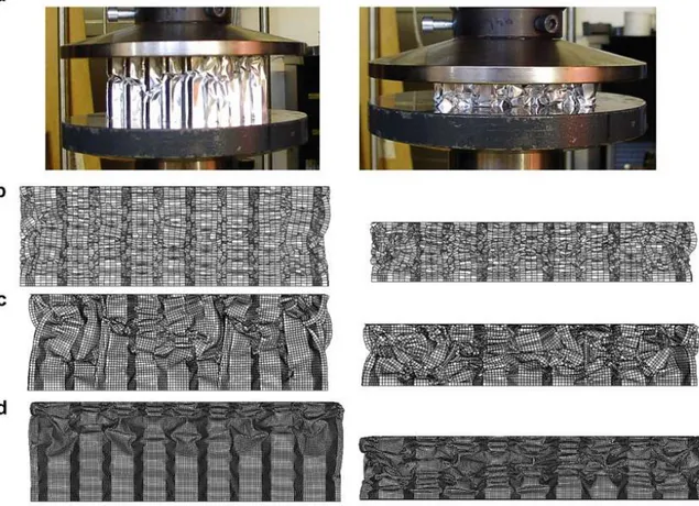
Figure 2.10: Stages of quasi-static compression test of aluminum honeycomb: (a) initial state, (b) buckling initiation, (c) progressive folding and (d) densification [32].
Initial studies on modeling the crush behavior have showed that these micro buckling/failure problems have typically meshing sensitive, so that a mesh sensitivity analysis was conducted. Three different mesh sizes have been chosen: 0.5, 1 and 2 mm, respectively. Figure 2.11shows that the deformation modes at 30% and 60% change slightly with three different mesh sizes. In experimental work, the aluminum honeycomb starts collapsing after
20
buckling. The collapse behavior was a mixture of global and local deformation. At 30% deformation the collapsed mode was the mixture of global (starts approximately from the middle of the honeycomb) and local collapse from the upper side of the honeycomb. However 2 mm mesh size produces pure global collapse.
Figure 2.11: Stages of quasi-static compression of aluminum honeycomb at 30% and 60% compressive strain: (a) experiment, and FE analysis with (b) 2 mm, (c) 1 mm and (d) 0.5 mm element size.
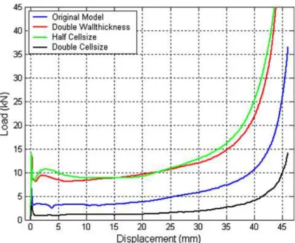
The numerical model with 2 mm mesh size was given higher load response than the numerical models with 1 mm and 0.5 mm mesh sizes. The difference has been get higher when the aluminum honeycomb has been get near to the densification region. This shows that the number of elements through the core thickness can change the global and local deformation responses and the load–deformation history (figure 2.12-13).
21
Figure 2.12: Numerical (three different mesh sizes) and experimental load–displacement responses of aluminum honeycomb under compression.
Figure 2.13: Effect of cell size and cell wall thickness on crush response on aluminum honeycomb in compression.
22
[33]Their work describes the results of experiments and numerical simulation studies on the impact and indentation damage created by low-velocity impact subjected onto honeycomb sandwich panels for application to the BIMODAL tram. The tested panels were subjected to low-velocity impact loading using an instrumented testing machine at six energy levels. Contact force histories as a function of time were evaluated and compared. The extent of the damage and depth of the permanent indentation was measured quantitatively using a 3-dimensional scanner. An explicit finite element analysis based on LS-DYNA3D was focused on the introduction of a material damage model and numerical simulation of low-velocity impact responses on honeycomb sandwich panels. Extensive material testing was conducted to determine the input parameters for the metallic and composite face-sheet materials and the effective equivalent damage model for the orthotropic honeycomb core material. Good agreement was obtained between numerical and experimental results; in particular, the numerical simulation was able to predict impact damage area and the depth of indentation of honeycomb sandwich composite panels created by the impact loading.
Figure 2.14: Force–time histories with impact energy for the sandwich specimens. (a) body-shell sandwich panels (GE/AH) and (b) floor sandwich panels (AL/AL) [33].
23
Figure 2.15: Comparison of impact damage areas for floor sandwich panels (al/ah) after impact loading. (a) 1.57 j, (b) 3.04 j, (c) 4.49 j and (d) 5.93 j [33].
Figure 2.16: Comparison of post-impact damage for sectioned sandwich panels after impact loading. (a) GE/AH specimens (4.13 j), (b) GE/AH specimens (6.00 j), (c) al/ah specimens (4.49 j) and (d) AL/AH specimens
24
[34]They presented results from a test developed to simulate the water impact (slamming) loading of sandwich boat structures. A weighted elastomer ball was dropped from increasing heights onto rigidly supported panels until damage was detected. Results indicated that honeycomb core sandwich panels start to damage due to core crushing at impact energies around 550 J. Sandwich panels of the same areal weight and with the same carbon/epoxy facings but using a novel foam core reinforced in the thickness direction with pultruded carbon fiber pins, did not showed signs of damage until above 1200 J impact energy.
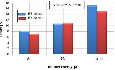
Two examples from the preliminary tests, shown in Figure 2.17, enable the influence of sandwich thickness and density to be examined. The damage energy is the energy at which damage was observed, defined simply as E=mgh. Thinner cores may provide improved impact performance due to improved deflection resulting in higher stored energy, Figure 2.14 a. Increasing density can improve the energy absorbed before damage is observed, as resistance to local crushing is improved, but there may be a plateau to this improvement as higher flexural rigidity results in lower deflection, Figure 2.17 b. It should be noted that the thicker sandwich panels did not show the same damage mechanism as thin panels. For the latter core crushing was apparent, while thicker panels also showed skin/core delamination.
Figure 2.17:Influence of core thickness and core density on energy to first damage, honeycomb core, a) OX 64 kg/m3, b) OX 20mm thick [34].
Four fully instrumented panels were tested, two honeycomb, one pinned foam core and one unreinforced core sandwich. Panels were loaded at drop height increments of one meter. In
25
order to examine repeatability the two meter drop height test was repeated three times on each honeycomb panel. Figure 2.18 summarizes the tests performed on the three materials.
Figure 2.18: Impact tests performed; HC: honeycomb. Grey indicates undamaged, black indicates first panel damage noted [34].
Figure 2.19 shows the damage incurred. The first damage of the standard (64 kg/m3) material was noted visually after a drop from 3 meters, and sectioning revealed this to be permanent crushing of the core (Figure 2.19 a). No skin debonding was noted. A second identical panel was then tested to confirm this result and again first damage was noted at 3 meters. Tests were continued on this second panel up to final complete failure, which occurred at around 1.3 kJ. Figure 2.20 presents the maximum loads and displacements recorded during the instrumented test series. For the honeycomb, the displacements ware very similar initially but beyond the energy required for core crushing there was a break in the plots of both force and displacement, suggesting that the damage introduced has modified the response of the structure.
26
Figure 2.19: Damage observed after impact: honeycomb, 3m 18.8 kg [34]
Figure 2.20: Recorded data from tests versus impact energy. a) Maximum loads (sum of four load cells) and b) central displacements [34].
[35] Perforation response and failure of sandwich panels with composite face sheets and aluminum foam core are investigated experimentally in their study. Quasi-static perforation and low-velocity impact tests were carried out by using a material test system and a drop weight machine, respectively. The load-displacement response, energy absorption and energy-absorbing effectiveness of sandwich panels were obtained and compared for quasi-static and impact tests. Effects of some key parameters on the overall energy absorption behavior of the panels were explored, such as impact energy, face sheets and core thickness, core density and indenter nose shape.
27
Figure 2.21: Force–displacement curves of sandwich specimens under conical indenter [35].
Figure 2.22: Effects of projectile nose shape on: (a) force–displacement curves and (b) energy absorption and energy-absorbing effectiveness (the error bars denote the standard deviations in replicate experiments)
28
It is important to fully understand the resistance of the sandwich panels subjected to impact loading conditions. For this reason [28] were studied the resistance of sandwich panels with different aluminum honeycomb cores, air sandwich panels (no core between the two face sheets) and monolithic plates of equivalent mass subjected to impact from foam projectiles. The deformation and the elastic spring-back of the honeycomb sandwich panels and the monolithic plates have been compared and discussed. The resistance of the panels and plates has been quantified by their back-face deflection with respect to the projectile impulse. Five different types of aluminum honeycombs have been used as the core material. The front-face sheet and the back-face sheet of the honeycomb sandwich panels are made of aluminum plate with 1 mm thickness. Cylindrical ALPORAS aluminum foams with a relative density between 9% and 11% were employed as the metal foam projectiles. They have been fired at several hundred meters per second towards the center of the panels and plates using a gas gun. The deflection histories of the back-face have been measured using a laser displacement sensor. From the deflection histories, the maximum deflection and the final deflection of the back-face has been distinguished. Deformation modes and failure modes of the individual component have been observed and classified into several categories. Moreover, the deflections of the honeycomb sandwich panels have been compared with deflections from air sandwich panels. It has been found that the honeycomb sandwich panels outperform both the air sandwich panels and the monolithic plates within an impulse range of 2.25 kNsm2~ 4.70 kNsm2. Outside this operational range, the advantages associated with employing the honeycomb sandwich panels as a protective structure upon impact of foam projectiles diminishes.
![Figure 2.10: Stages of quasi-static compression test of aluminum honeycomb: (a) initial state, (b) buckling initiation, (c) progressive folding and (d) densification [32]](https://thumb-eu.123doks.com/thumbv2/123doknet/3428434.100126/38.892.144.745.380.890/figure-compression-aluminum-honeycomb-buckling-initiation-progressive-densification.webp)
![Figure 2.14: Force–time histories with impact energy for the sandwich specimens. (a) body-shell sandwich panels (GE/AH) and (b) floor sandwich panels (AL/AL) [33]](https://thumb-eu.123doks.com/thumbv2/123doknet/3428434.100126/41.892.89.817.556.833/figure-histories-impact-energy-sandwich-specimens-sandwich-sandwich.webp)

![Figure 2.17:Influence of core thickness and core density on energy to first damage, honeycomb core, a) OX 64 kg/m3, b) OX 20mm thick [34]](https://thumb-eu.123doks.com/thumbv2/123doknet/3428434.100126/43.892.93.825.625.946/figure-influence-thickness-density-energy-damage-honeycomb-thick.webp)
![Figure 2.20: Recorded data from tests versus impact energy. a) Maximum loads (sum of four load cells) and b) central displacements [34]](https://thumb-eu.123doks.com/thumbv2/123doknet/3428434.100126/45.892.111.781.453.789/figure-recorded-versus-impact-energy-maximum-central-displacements.webp)
![Figure 2.21: Force–displacement curves of sandwich specimens under conical indenter [35]](https://thumb-eu.123doks.com/thumbv2/123doknet/3428434.100126/46.892.220.672.106.469/figure-force-displacement-curves-sandwich-specimens-conical-indenter.webp)