DAMAGE TOLERANCE OF COMPOSITE HONEYCOMB SANDWICH PANELS UNDER QUASI-STATIC BENDING AND CYCLIC COMPRESSION
by
MATTHEW CLAIRE TAYLOR
M.S., University of Southern California (1986)
B.S., University of Minnesota (1980)
SUBMITTED IN PARTIAL FULFILLMENT OF THE REQUIREMENTS OF THE
DEGREE OF
MASTER OF SCIENCE
IN AERONAUTICAL AND ASTRONAUTICAL ENGINEERING at the
MASSACHUSETTS INSTITUTE OF TECHNOLOGY June 1989
Copyright Matthew C. Taylor 1989
The author hereby grants to M.I.T. permission to reproduce and distribute copies of this thesis document in whole or in part.
Signature of Author Z- W-vw ---- LO W,,- -- .
Department of Aeronauticg and Astronaueics
Certified by
Accepted by_
Professor James W. Mar, Thesis Supervisor D Wtment 4,earonauticsjand Astronautics, M.I.T.
MV-40 IN lr~fofessor Harold Y. Wachman A1t par tment
JUN 07/ 1989
WITHDRAW M.I.T. UBRARIM L1BRA4RI6 Committee k~ W; - ~~ - - - - ---- --_ABSTRACT
DAMAGE TOLERANCE OF COMPOSITE HONEYCOMB SANDWICH PANELS UNDER QUASI-STATIC BENDING AND CYCLIC COMPRESSION
by
Matthew Claire Taylor
Submitted to the Department of Aeronautics and Astronautics on May 19, 1989 in partial fulfillment of the requirements
for the Degree of Master of Science
The damage resistance and damage tolerance of minimum gauge face sheet sandwich panels subjected to quasi-static four point bending and cyclic column compression, was experimentally investigated for a graphite/epoxy plain weave fabric and Nomex honeycomb core. Face sheets with [0/901,
[+-45], [0/901s, and [+-45]s layups were constructed from AW193PW/3501-6 prepreg graphite/epoxy fabric and three thicknesses of Nomex honeycomb, 1.0", .687" and .375". Four point bending specimens (2.75" x 14") were constructed with three core thicknesses. Undamaged specimens were constructed with a 2" Nomex test section bounded by aluminum honeycomb core for load point reinforcement. Damage was inflicted with a spring propelled rod (.5" diameter hemispherical tup; .105 slug) at five levels of kinetic energy. Visual and x-ray inspection measurements were made to assess damage. Quasi-static four point loading provided failure moment, face sheet buckling stress and specimen deflection data. Damaged and undamaged column specimens (3.25" x 14") with reinforced grip sections were tested for fatigue life under compression-compression cyclic loading (R =.1). Results indicate that damage resistance increases with face sheet thickness and panel thinness. Residual strength of the 2 ply face sheet is dramatically reduced (0/90, 50 %; +-45, 30 %). The Nomex core limits ultimate bending moment in undamaged 2 ply specimens and all 4 ply specimens, with or without damage. Limited fatigue tests indicate a tremendous high load bearing longevity for undamaged 0/90 specimens. Notch sensitivity of the damaged 0/90 specimen cuts its load capability by at least half. Notch insensitivity of the damaged +-45 specimen allows for 60% of critical load to be carried to .5 million cycles.
Thesis Supervisor: James W. Mar
J.C. Hunsaker Professor of Aerospace Education
AKNOWLEDGEMENTS
I would like to thank all those people who have made this work possible. Captain Robert W. Sherer and Commander James G. Ward gave me moral and financial support for this extracurricular study over the last three years. My thanks to Carl Varnin and Simon Lie who got me started in the TELAC lab and made me feel welcome. I extend my special gratitude to Al Supple who has lead me through many a trying day in the lab, fixed the computer for me and brought me back "on line" as well. Al was there always willing to help in every way. A very warm and heartfelt thankyou is extended to Professor James Mar who got me interested in composites two years ago and offered an avenue of study that is closed to most part time students. Professor Mar's friendliness and helpful instruction will always represent M.I.T. to me.
Aknowledgements would never be complete without mentioning the "worker bees" - The UROPers. I was lucky to be stuck with such a fine group. All hand selected so they had to call me "Sir". My thanks to Dave Wright who stepped in to help when I needed it down the stretch. My warmest appreciation and gratitude is extended to Chantal Moore who helped me break over a hundred specimens and slugged through hundreds of computer files, always producing a polished result. My eternal appreciation and gratitude has been earned by Teri Centner and Cristina Villella who upon hearing Paul Lagace match their names with me, said "Oh no.. we'll have to call him Sir ". They didn't have to say the "Sir" word in the lab, as long as they worked. And they did! Teri and Cristina constructed specimens through the summer while I was called away to summer training. They did everything that could have been asked for the last 13 months. I couldn't have finished without the dedication demonstrated by these four fine young people.
I am lucky to have three young ladies at home that have earned this degree through as much or more sacrifice as I. My lovely daughters, Autumn and Madeline have never known their father when he hasn't had a book in his hand. They tried so hard to leave me alone to study, but often it wasn't enough and I barked at them. This is the price I wish I hadn't paid for this degree. I can only claim part ownership to this degree. My wife April has put in as much sweat, work and frustration as I have. She has raised the girls and kept up the house without me. She has consoled me, kicked me in the pants and even used child psychology to keep me going. She has typed 99% of this thesis to help me end my ego experience. I hope someday I can repay her. Until then, April you have my eternal loving gratitude and
FOREWARD
This work was conducted at the Technology Laboratory for Advanced Composites (TELAC) in the department of Aeronautics and Astronautics at the Massachusetts Institute
of Technology. The work was sponsored by Boeing Helicopters under purchase order TT 70935. The project monitor was Steve Llorente.
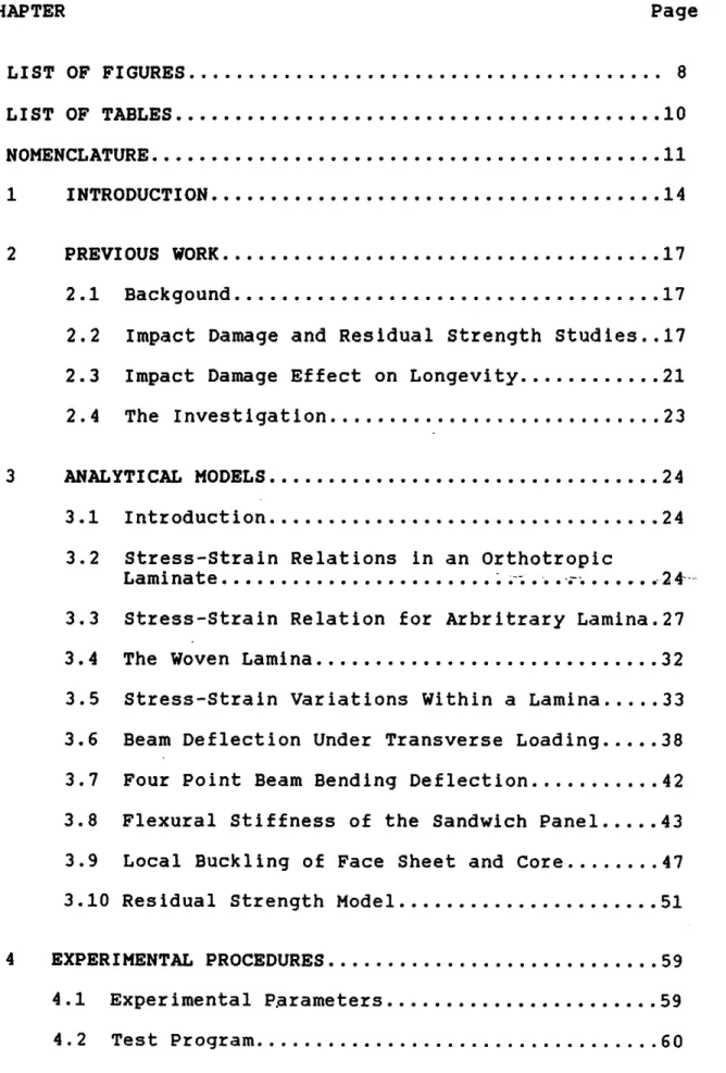
TABLE OF CONTENTS CHAPTER Page LIST OF FIGURES... 8 LIST OF TABLES... NOMENCLATURE ... 1 INTRODUCTION ... 2 PREVIOUS WORK... 2.1 Backgound... 2.2 Impact Damage and Residual Strength 2.3 Impact Damage Effect on Longevity... 2.4 The Investigation...
3
ANALYTICAL MODELS...
3.1 Introduction...
... ... Studies. e...e ....10
.11
.14
.17
.17
.17
.21
.23
... 24 ... 24 3.2 Stress-Strain Relations in an OrthotropicLaminate... . ... 3.3 Stress-Strain Relation for Arbritrary Lami 3.4 The Woven Lamina ...
3.5 Stress-Strain Variations Within a Lamina.. 3.6 Beam Deflection Under Transverse Loading.. 3.7 Four Point Beam Bending Deflection... 3.8 Flexural Stiffness of the Sandwich Panel..
3.9 Local Buckling of Face Sheet and Core ... 3.10 Residual Strength Model...
4 EXPERIMENTAL PROCEDURES ... 4.1 Experimental P.arameters... 4.2 Test Program... .24--.27 .32 .33 .38 .42 .43 .47 .51 .59 .59 .60 · · · · · · · · · · · · · · · · · · · · · · · · 0 0 0 9 0· "QOO'O'O0"" "'OOOO''''" ... o
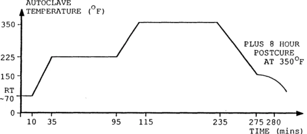
4.3 Specimen Description ... 63 4.4 Manufacturing Procedures...66 4.4.1 Layup ... ... 66 4.4.2 Laminate Cure ... 67 4.4.3 Post-Cure...69 4.4.4 Trimming ... 69 4.4.5 Core Assembly...70 4.4.6 Bond Cure... 70
4.4.7 Load Tab Cure...71
4.4.8 Panel Machining ... 72
4.4.9 Coupon Machining...72
4.4.10 Strain Gauging...73
4.5 Testing Procedure and Data Acquisition... 75
4.5.1 Impact Results ... 75
4.5.2 Damage Assessment...78
4.5.3 Four Point Bending... 79
4.5.4 Static Panel Compression...83
4.5.5 Core Compression and Indentation ... 84
4.5.6 Panel Fatigue...86
5 EXPERIMENTAL RESULTS ... 88
5.1 Impact Test Results ... 88
5.1.1 Impact Velocity and Energy ... 88
5.1.2 Impact Force ... 89
5.1.3 Impact Energy... 93
5.2 Damage Assessment ... 95
5.3 Quasi Static Four Point Bending ... 102
5.3.2 5.3.3 5.4 Panel Panel Deflection Failure Stresses Under Load. AndA StrAin Compression Results. 5.5 Core Compression Results...
5.5.1 Core Indentation Results 5.6 Panel Fatigue Results ...
... 107
... 108
... 109...114
... 114
... 115
6 CONCLUSIONS ... 6.1 Impact Results ... 6.1.1 Impact Force...6.1.2 Force - Time History...
6.1.3 Impact Energy and Damage Assessme 6.1.4 Damage ... 6.2 Residual Strength...
6.2.1 Analytical Comparisons... 6.2.2 Failure Stress and Impact Energy. 6.2.3 Damage Propagation... 6.2.4 Mar - Lin Relation... 6.3 Panel Longevity...
7 CONCLUSIONS AND RECOMMENDATIONS.
7.1 Conclusions... 7.2 Recommendations ... REFERENCES. APPENDIX A: APPENDIX B: APPENDIX C: •..•...•.•.•....oee. Experimental Results; T Sub-Lamina Geometry of Panel Deflection Graphs
ables the Wo and Figures. ven Ply...
.117
.117
.117
.118
.119
.120
.122
.122
.123
.125
.128
.130
.132
.132
.133
.135
.137
.177
.181
u &&·u * aa U~··V · · · · · · · · ,··~ · · · ·LIST OF FIGURES Figure Figure Figure Figure Figure Figure Figure Figure Figure Figure
Figure 3.11 Cross Sectional View of a Dimpled Face Sheet Under Compressive Loading .... Figure 3.12 A [0/901 Panel With Arbitrary
Face Sheet Damage Under Compression Figure 3.13 Mar - Lin Relation with Corrections... Figure 4.1 Basic Sandwich Panel ...
... 50
... 52
... 58
... 64
Reinforced Sandwich Panel... Static Compression Sandwich Panel. Fatigue Sandwich Panel... Laminate Cure Layup... Laminate Cure Cycle... Panel Bend Cure Layup ... Static Core Compression and Indent Strain Gauge Configurations... ... ... .. 64 ... 65 ... 65 ... 68 ... 69 ... 71 ation Coupon73 ... 74
Figure 4.10 Specimen Holding Jig ... 76
3.1 3.2 3.3 3.4 3.5 3.6 3.7 3.8 3.9 3.10 Global Coordinate System ... 25
Ply Orientation With Respect to Loading Axes... 27
Fabric Tow Geometry Within a Lamina ... 32
Coordinate and Displacement Orientation...34
Geometry of Deformation in the z-x Plane...34
Anticlastic Curvature Under Pure Bending...40
Four Point Beam Loading...42
Panel Side View...46
Honeycomb Core Bending and Loading (a) Panel Element Bending...47
(b) Face Element Loading and Curvature...47
Core Deformation...48 Figure Figure Figure Figure Figure Figure Figure Figure 4.2 4.3 4.4 4.5 4.6 4.7 4.8 4.9
Figure Figure Figure Figure Figure Figure Figure Figure Figure Figure Figure Figure Figure Figure Figure Figure Figure Figure Figure Figure Figure Figure Figure Figure Figure Figure Figure 4.11 4.12 4.13 4.14 4.15 4.16 4.17
5.1
5.2 5.3a5.3
5.4
5.5
5.6
5.7
5.8
5.9
5.10
5.11
5.12
5.13
5.14
6.1
6.2 6.3B.1
B. 2Damage Diameter vs. Impact Energy, 1" Panels..100
Damage Area vs. Impact Energy, 1" Panels...101
Compressive Fracture Modes for Damaged Face Sheet...104
Core Failure Modes ... 107
Failure Stress vs. Impact Energy...110
Failure Stress vs. Impact Energy, 1"Panel...111
Failure Stress vs. Damage Cross Sectional....112
Failure Stress vs. Damaged Cross Section ... 113
Longitudinal Section of Dimple Indentation...127
Mar - Lin Residual Strength; +-45... 129
Mar - Lin Residual Strength; 0/90... 129
The "Imaginary Bi-Ply" ... 177
Tow Deflection Angle Within Weave...17•)
FRED's Striking Unit... FRED; Impacting Rod Mechanism... Four Point Bending Installation ... Face Sheet Damage Photography... Panel Compression Test... Core Compression Test... Core Indentation Test... Impact Velocity/Energy vs. Spring Disp Force-Time History: Impact Spectrum. Impact Spectrum - Damage... Force-Time History: Damaging Impacts Cross Sectional Damage Projection.... Damage Diameter vs. Impact Energy .... Damage Area vs. Impact Energy... ... 77 ... 77 ... 81 ... 83 ... 84 ... 85 ... 86 lacement.89 ... 91 ... 92 ... 94 ... 96 ... 98 ... 99
LIST OF TABLES
Material Properties of AW 193PW/3501-6 ...29
Reduced Stiffnesses ... 29
Invariant Values for AW 193PW/3501-6 ... 33
Reduced Stiffnesses Based on Orientation...33
Stiffnesses for Orthotropic Plain Weave Laminates...38
Table 4.1 Four Point Bending Residual Strength Test Matrix ... Table 4.2 Undamaged Panel Strength Test Matrix. Table 4.3 Panel Longevity Test Matrix... Table 5.1 Maximum Impact Energy... Table 5.2 Maximum Impact Forces... Table 5.3 Dimple Lengths at Fracture Load ... Table 5.4 Mean Face Sheet Failure Stresses ... Table 5.5 Core Indentation Results by Cell Row Direction... Table 5.6 Residual Strength Estimates... Table B.1 Tow Bending Within Fabric... ... 61 ... 62 ... 66 ... 89 ... 90
... 105
... 109
...114
... 115 · ·· ·· · rl.· Table Table Table Table Table 3.1 3.2 3.3 3.4 3.5NOMENCLATURE 47 stress o shear stress £ strain Y shear strain C stiffness matrix S compliance matrix V Poisson's ratio E Young's modulus
Q0 reduced stiffnesses matrix G shear modulus
T transformation matrix
Ui invariant constants
8 ply orientation t, t,y lamina thickness
a deformation angle x,y,z cartesian coordinates u,v,w cartesian displacements
K curvature
Nf,Nx force/unit width in face sheet
M, moment/unit width f face sheet thickness h panel thickness
W,b panel width
Aii extensional stiffnesses B6 coupling stiffnesses Dq bending stiffnesses r,R radius of curvature I moment of inertia
s curved path coordinate P transverse load
I moment arm
L panel deflection section
8SrA panel deflection (outboard) angles q load / unit length
d rupture diameter D dimple axis length
y,,y, bending region coordinates
modal amplitude of generalized displacement
Ic core modulus (in z direction) U potential energy
Wet external work TT total energy
Hc fracture parameter
S standard deviation of a sample n population
N fatigue cycles R fatigue ratio
Super-scripts:
dz/dxz
neutral plane or axis
Sub-scripts: Ixx; ,yy f cr d x,y,z 1,2,3 0 dz/dxz ; dz/dyz face sheet critical deformed
direction of action with respect to specimen direction of action with respect to material undamaged, control value
Intentionally left blank for notes:
CHAPTER ONE INTRODUCTION
The sandwich structure has been studied intensively for the past fifty years in order to understand its stress and strain mechanics; its simple design is used for everything from cardboard boxes to supersonic aircraft control surfaces. The sandwich structure can be constructed from virtually any material in order to satisfy its desired use. The three components for construction are two face sheets which carry in-plane loads and a core bonded between the face sheets. The core provides structural stability by maintaining the load bearing face sheets at a constant separation distance, along with maintaining shear stiffness parallel to the faces and normal stiffness perpendicular to the faces. The face sheets carry the compression and tension loads that resist panel bending.
Beyond the beauty of its simple construction, the sandwich panel's reason for being lies in its high strength to weight ratio and bending stiffness. Thus the sandwich structure has been applied to aircraft construction wherever possible and in whatever combination of materials thought feasible. Face sheet materials have included wood, fiberglass, and metals. The core has consisted of balsa wood, pine, glue pulp, polymen foam and light weight metals. The need to reduce weight led to the invention of another structural form - the honeycomb core.
With the advent of advanced filamentary composite
materials which possess exceptional strength-to-weight advantage and the development of aluminum and Nomex honeycomb cores; it is now possible to construct extremely weight efficient composite honeycomb core sandwich panels for aerospace application. Laminate face sheets can be tailored for specific loading orientations, strengths and durability. The honeycomb core can be made from aluminum, phenolic or Nomex material. It provides flexural stiffness, and shearing resistance through its thickness, shear modulus, and density, respectively. Because honeycomb core panels (HCPs) are typically used for part of the aircraft's external surface, the durability aspect of HCP design is now on a par with strength, stiffness and light weight.
"Durability" is the combination of structural longevity and economics of construction and repair. The filiamentary composite fabric facilitates simplified constuction and thus economic production. Structural longevity refers to damage resistance, damage tolerance, and fatigue life. Filamentary composites have exceptional undamaged characteristics, but their heterogeneous composition and brittle nature make their failure criteria complicated and specific to the structure and its accumulated damage.
This study examines the damage resistance and tolerance of a specific graphite epoxy/honeycomb core sandwich panel under quasi-static bending and compression-compression fatigue loading. The objective is to determine the
characteristics of the panel's resistance to damage, along with its maximum capabilities for various parameters of construction and load orientation.
CHAPTER TWO PREVIOUS WORK
2.1 BACKGROUND
A great effort has been made in the last fifteen years
to determine the fracture principles and mechanics of filamentary composites. Work has focused on the factors
that tend to degrade composite laminate structure and the
composite material structures.
Composites have some unique problems in that they are susceptible to damage at low levels of imparted energy such as might happen from runway debris, tool drops or hail. Further, this damage from impact may not be visually detectable. Often the damage inflicted to a sandwich composite panel is below the surface between plies and at
the laminate core interface.
2.2 IMPACT DAMAGE AND RESIDUAL STRENGTH STUDIES
Many investigators have conducted controlled impact tests on composite sandwich panels to determine damage infliction at prescribed energy levels. Oplinger and Slepetz [11 impacted graphite and S-glass epoxy HCP's with a
2 inch diameter steel ball. They found that graphite epoxy was very brittle compared to S-glass because of its low strain to fracture (less than 1% for G/E, about 3% for S-glass). The Nomex was found crushed under the impact due to the graphite face rupturing, while the S-glass face sheet
bridged the crushed core's indentation to remain intact and absorb some of the impact. The graphite face sheets absorbed energy by progressive fracture along planes defined by the laminate fiber orientations due to the low strain capability relative to the indentor radius. The authors point out the need for a larger strain to failure level for graphite to be damage resistant and suggest that a tougher core (more dense) will prevent large impact damage at a weight penalty. Oplinger et al also suggests a hybrid face sheet of graphite and S-glass to improve resiliency at the cost of ultimate strength.
Rhodes [2] also recommended a hybrid face sheet as a means of raising the damage threshold for graphite sandwich structures. He compared graphite epoxy to Kevlar-491 epoxy under projectile impacts. Once again graphite was found to be more susceptible to breaking. Rhodes found that core
indentation (crushing) during impact causes high local stresses in the face, which precipitates buckling. He also impacted panels under compression and was able to cause buckling at impact energy levels well below that required to initiate visible damage. Rhodes suggests a stiffer core as did Oplinger and Slepetz, as well as thicker face sheets to reduce the "bearly visible impact damage" (BVID) threshold. Rhodes maintains that a visual inspection for damage is
inadequate.
The work of Adsit and Waszezak [31 supports Rhodes recommendation. After performing impacts with stones, a
.63cm tip radius and 2.54cm tip radius, Adsit et. al. found a panel strength reduction of up to 50% at the BVID (barely visible impact damage) level. Compressive residual strength decreased as impact energy was increased, regardless of impactor head. The Heat Resistant Phenolic honeycomb core (88kg per cubic meter) was not impact resistant, which resulted in core crushing and face sheet delaminations. Both forms of damage cause a localized loss of stability and make face wrinkling more possible. Adsit et. al. also found that distributing the impact energy over a broader surface (ie: .63cm to 2.54cm impactor radius) will add approximately 25% to the compressive residual strength. Data also implies that impact energy with the wide blunt tip can be doubled with no increase in panel damage or reduction in residual strength.
Gwynn and O'Brien [41 and Husman, Whitney and Halpin (5] each arrived at the same conclusion regarding impact energy's effect on compressive failure stress. There is a minimum plateau of residual strength (minimum stress) where greater impact energy will not create further damage. Husman et. al. [5] predicts this at less than face sheet penetration velocities. For velocities at penetration and higher, the residual failure stress approximates that of a hole of similar size. Gwynn et. al. [4] demonstrates that thick laminates have higher failure strains than thin laminates, after each is impacted at the same energy per laminate thickness. Thicker laminates dissipate impact
energy through matrix cracking and not local bending and stretching of fibers because of impact displacement. Delaminations within the face sheet were also associated with impact induced matrix cracking. The delaminations are peanut shaped and oriented (long axis) with the filament direction in each ply. once again, a source of localized buckling instability. Bernard and Lagace [6] examined the impact resistance of sandwich panels utilizing (+-45/0]s AS4/3501-6 graphite epoxy and three different core materials; Rohacell, Nomex and aluminum honeycomb. They established the BVID level at 1 Joule of impact energy; Nomex damage threshold at .4 Joules; and confirmed core crushing to be cell wall buckling. Panels with stiff cores like the aluminum had equal amounts of debonding and face sheet damage while Nomex debonding increases with core stiffness. Bernard also implanted delaminations in the laminates and debonds between face and core to compare against impacted panels. The result was a loss in local stiffness and a reduction in buckling stress threshold. Overall, the buckling load dropped by 8 to 19% for damaged panels and was found to be independent of the core material. This result may simply be a coincidence, because it violates Lie's [71 analytical buckling equation for an undamaged
panel; which calls for the flexural rigidity term EI (Young's modulus times the beam's moment of inertia). If the cores were the same thickness this could be explained by negligible core density and stiffness compared to the face
laminates.
Lie [7] performed impacts at three energy levels and measured the dynamic strains of the panel during impact. With this data he compared it against an analytical computer model derived from Hertzian contact theory. Damaged panels of various thickness (all Nomex cores) were tested for residual strength under compression and compared with the afore mentioned critical buckling equation and the Mar-Lin residual strength relation. He found the [+-451 face sheets to be notch insensitive and fail at constant net-section stress. The [0/901 laminates were notch sensitive and so failure ocurred at stress levels lower than the net-section stress. Lie's impact tests found ,7 ft-lbs to be the damage threshold where core crushing begins, followed by matrix cracks, delamination and fiber rupture at 1.5 ft-lbs.
2.3 IMPACT DAMAGE EFFECT ON LONGEVITY
Ramkumar [8) examined the effect of low velocity
impacts on laminate columns of 42 and 48 plies. His conclusions are:
-Tension provides less threat to impact damaged laminates.
-Delaminations propagate to cause early failure in compression-compression fatigue loading. This also
provides the lowest strain failures. (Fatigue test
R = oo ).
delamination propagation.
Componeschi et. al. [9] studied stiffness reduction as an indicator of fatigue damage. He concludes that [0,901s laminates don't experience a loss of longitudinal stiffness. The stiffness is degraded when the 90 degree ply is damaged. Camponeschi et. al. concludes that Ex in quasi-isotropic laminates reduces to an equilibrium state where no significant damage occurs until failure. They also claim
that the major degradation in shearing stiffness occurs early in the panel's fatigue life.
"Sudden - Death" and "Degradation" fatigue models were proposed by Chou et. al. [101 to predict residual strength throughout the laminate's fatigue life. Tests indicate that the "Sudden - Death" model where residual strength doesn't degrade, provides a good model for laminates with a large majority of on-axis uni-plies. The "Degredation" model describes increasing strength reductions throughout the fatigue life. It predicts residual strength for off-axis uni-ply laminates.
Finally, Reifsnider, Schulte and Duke [111 propose three regions of damage: a stage of adjustment; coupling and growth; and final damage to failure. Fatigue failure modes and damage development is described for each.
Asit [31 performed fatigue testing on sandwich panels with a necked test section. He used a 4 point bending jig that oscillated at 1 Hz. to fatigue impacted panel test sections. Results indicate that increases in impact energy
shorten the specimen fatigue life, and ruptured fibers from impact have a greater effect on life than delaminations from a blunt impact.
2.4 THE INVESTIGATION
This investigation follows the work of Simon Lie [7]. In order to maintain a consistent data base, similar materials, dimensions, impact and test methods are employed. Residual strength will be tested through a bending test as used by Adsit [3]. However, the fatigue portion will be a follow-on study to Lie's static strength experiments. Similar specimens will be impacted, examined and then fatigued under compression-compression (c-c) loading at various peak loads. Damage propagation will be observed and measured.
CHAPTER THREE ANALYTICAL MODELS
3.1 INTRODUCTION
This chapter examines the properties and mechanics of orthotropic symmetric laminates and their influence as face sheets of a honeycomb sandwich panel. Material properties will be based on previous tests and classical lamination plate theory. The characteristics of the woven lamina used in this investigation will be discussed. Stress and strain relations within the laminate will be developed and extended to the panel under pure bending. The derivation of homogeneous beam bending and its application to the four -point bending problem will be reviewed. A residual strength face sheet damage propagation under compression because of panel bending will be discussed. And finally, a global buckling model for one face sheet will be proposed.
3.2 STRESS - STRAIN RELATIONS IN AN ORTHOTROPIC LAMINATE Principle material directions will be oriented to the three dimensional global coordinate system x, y and z, defined by test specimen geometry, illustrated in Figure
3.1, Global Coordinate System. Specimen axes will be
parallel or coincident to an orthogonal coordinate axis as follows:
x - longitudinal y - transverse
z - normal (to panel face)
Principle material directions or axes will be assigned
numbers 1, 2, and 3. The direction of filaments in a uni-ply or the "fill" filament direction in a woven ply will be refered to as the principal material axis 1. The perpendicular axis to 1 which lies in the ply's plane will be axis 2. The "right hand rule" will define the third axis which is normal to the reference ply. Tensor and contracted notation using x, y, z and 1, 2, 3 as subscripts will be used throughout this report to define directions and states
of stress - strain.
Figure 3.1 Global Coordinate System
Jones [121 provides a discussion of background material on this subject. A plane stress state is defined by assuming that 0,= 0, Tz.= 0, T,= 0. This assumption is reasonable for a thin laminate. An orthotropic material allows for the reduction of 27 independent stiffness constants from the stiffness matrix Cij. for the general case (anisotropic material). Where;
- = C ij i,j = 1,...6 (3.2.1)
Ar-0'g
crt
(T
r, =14&
C1 C2,Cst,
0 0 0can be reduced further with
CIt C,5 0 0 Czz Cz2 0 0
Czz C
33 0 0 0 0 C,,, 0 0 0 0 CSr 0 0 0 0 the plan0
o
£0
0 ( (3.2.2) C e stress state assumptions.O;
r C,C
it
C ,C,
I
20
0EI
Lo = C7
C
c, 0'
Tt
0
0
C&
,
(3.2.3)Note: C,, = C,, due to orthotropic symmetry.
The above relation can also be expressed in the compliance form.
Sq
= S(j
~
c,
S,,
S,
0
t = S S, S - 0
Cr
Where: S
/E,
o
=
=
/E,
Where: S,, = 1/E l SIZ = - 2I/EI = -,/E z
(3.2.4)
S,= 1/E
Ez Iz
S6S=
S6&1/G
1 The stiffness matrix for the orthotropic plane stress state can be determined more easily from the reduced stiffnessesform. 0"? = i IL,
a,
0
0,, O E 0t2 0 Eza 0 Q (3.2.5)Where the reduced stiffnesses are:
Q,1
=
-SIZ /(S S -sL, )
Q, = i/s,
(3.2.6)Q, = Set/S set--s,:, )
Q
t =
SZ.
/ ( S,,1
S-St)
QIM27 Sit /(Suit
5f2S .~
In terms of engineering constants
Q,, = E,/(1 -~'~, ,)
Qz
E
2/1(I - Vt•
E,I
EV/(1 ( - = VZ2,) E / (I / ) (3.2.7) Q ~. = G,Thus four independent material properties, E, Ez, V,2 and G
will determine the stress - strain relations in a "special orthotropic lamina". That is, the principle material axes 1 and 2 are aligned with the natural body loading axes x and y.
3.3 STRESS - STRAIN RELATION FOR ARBRITRARY LAMINA 3.3.1 Orientation
A stress - strain relation must be developed for lamina constructed from orthotropic plies of arbitrary orientation with respect to the geometrically natural coordinate directions. In this experimental work, 2 and 4 ply lamina facesheets will be subjected to compressive loads oriented in the direction of the specimen's longitudinal axis. Individual ply orientation can range from -90 to +90 with respect to the longitudinal or loading axis, x.
01
0XX
Figure 3.2 Ply Orientation With Respect to Loading Axes Stress and strain transformations express the stresses
and strains of an x-y coordinate system in a 1-2 coordinate system. The transformations are commonly written as
(TY = IT] (T, E = IT] Ez (3.3.1)
where
wcos
sin28
2sinecose
IT]
=
sin
e
cos
z8
-2sin6cos0
-sin9cos8 sinScosO cos28-sin z
and the inverse
T
cos
6
sin 8
sinGcos8
TI = sin'
I
cos2 -sinecosj
-2sinecos8
2sinecos8
cos
?
8-sin The reduced stiffness matrix for any ply orientation 8 can be found through matrix multiplication.[i] =
TIT]-' [Q
[TI"T (3.3.2)where Qij : transformed reduced stiffnesses
(TITT: inverse transpose of IT]
The orthotropic lamina becomes generally orthotropic after
transformation.
cry
0
1
Ey(3.3.3)
The stiffness constants are simplified by Tsai and Pagano [13].
Q,, = U, + Uz cos 28 + U7 cos 46 Off = U, - U3 cos 40
Qzz= U, - U2 cos 28 + U~ cos 48 (3.3.4)
Qr, = (1/2)U2 sin 26 + U3 sin 48 Ott= (1/2)Uz sin 28 - U3 sin 40
Q&= U. - U3 cos 4e
in which U, = [3Q,, + 3Q0 + 2Q, + 4Q4]/ 8 Uz = [Q,, - Q0/ 2 U = [Q",, + Q22 - 20,, -4Q64]/ 8 (3.3.5) UY = IQ,, + Qu + 6Q,z - 4Q64]/ 8 U- = [Q,, + Qzz - 2Q, + 4QC]/ 8
Note that the Q..are composed of invariant terms U; , which are independent of ply orientation and dependent on material
stiffnesses, only.
Using material constants determined for AW193PW/3501-6 graphite epoxy fabric, within TELAC and Boeing Helicopters, [Q] can be determined.
TABLE 3.1
Material Properties of AW193PW/3501-6 Graphite/Epoxy
E,
E
E
V1.E(9_qS)
2
TELAC 9.09 Msi Boeing 9.36 Msi 8.72 Msi 9.30 Msi .087 .050 2.99 Msi 3.00 Msi Recall that ,,E,z= 2)•1E,so 2 z,= Et/E, or (8.72/9.09) .087 = .083 = •r, (9.30/9.36) .05 = .050 = Vz, TABLE 3.2 Reduced Stiffnesses TELAC Values: Boeing Values: Q,, = 9.09/(1-(083).087) = 9.16 Msi Q2z = 8.72/(1-(.083).087) = 8.78 Msi Qz = .087 (8.78) = .764 Msi Q,, = 9.36/ (1- .05 ) = 9.38 Msi Q
,,=
9.30/ (1- .052) = 9.32 Msi Q,a = .05 (9.32) = .466 Msi By substituting the .083 .050 TELAC B.H.compliance matrix and performing transformation for a given ply orientation with respect to the loading axis, we find:
1/E, = 1/E,cos 8 + (1/G, - 22•,/E,)sin zcos 6 + 1/Esin 6
7,y= Ex[VIz/E,(sin 9 + cos ~) - (1/E, +1/Ez-i/G,)sinz6cos28]
1/E = 1/E, sin28 + (1/G,i - 2v,/E, )sin2 8cos 8 + 1/Ezcosv8
1/Gxy= 2(2/E, + 2/E z + 4,1/E, - 1/G,f)sinz8cos 8
+ 1/G z(siny6 + cosvB) (3.3.6)
Since this investigator did not measure G,, with a specific shear test (such as the Rail Shear test), the above relations will be used to indirectly determine G,, from the +-45 compression tests. E was found to average 3.0 Msi by Lie [71 and Boeing Helicopters. By substituting 8 = 45°and
Ex = 3.0 Msi, we have the following
1/E, = (1/E, - 2jz/E, + 1/G,z + 1/Ez)/4 = 1/Ey (3.3.7)
where G,z is the only unknown. Solving for G,z
-I
GI = [4/E x - 1/E, - 1/E z + 2Azf/E,] (3.3.8)
and substituting:
TELAC values G,1 = .887 Msi
Boeing values G,1 = .885 Msi
Similarly, Gyp can be found for any orientation now that G is known. For 8 = + 45ý:
1/GV ,= [2/E, + 2/Ez + 4Vz1/E, - 1/G,I ]/ 2 + 1/2 G,2 (3.3.9)
TELAC GVy= 4.10 Msi Boeing Gxy= 4.44 Msi
transformation equations and stress - strain relations are available to calculate the stresses and strains within a ply at any given orientation 8, with respect to the axes of applied load. This is facilitated with the Tsai & Pagano invariant reduced stiffnesses equations (3.2.5). Substituting engineering material constants into the invariant relations produces the following invariant values.
TABLE 3.3
Invariant Values for AW193PW/3501-6
U, Uz U3 Uq UV (Msi)
TELAC 7.36 .19 1.61 2.37 2.50 Boeing 7.57 .03 1.78 2.24 2.66
The reduced stiffnesses calculated from equation (3.3.4) using TELAC values are:
0,, = 7.36 + .19 cos 28 + 1.61 cos 46
= 2.37 - 1.61 cos 48
z = 7.36 - .19 cos 20 + 1.61 cos 48 (Msi units)
=,, (.19/2) sin 28 + 1.61 sin 48
= (.19/27 sin 28 -ý 1.61 sin 46
Q,&= 2.5 - 1.61 cos 46
Reduced stiffnesses are calculated using TELAC values, for given orientations.
TABLE 3.4
Reduced Stiffnesses Based On Orientation
8 = 00 100 200 300 400 450 5,, 9.16 8.77 7.79 6.65 5.88 5.75 2,z .76 1.14 2.09 3.18 3.88 3.98 12 8.78 8.41 7.49 6.46 5.81 5.75 Ots 0 1.07 1.65 1.48 .64 .095 OQ,
0
-1.00 -1.52 -1.31 -.46 .095 QO6 .89 1.27 2.22 3.31 4.01 4.11Values are in Msi or 10' psi.
3.4 THE WOVEN LAMINA
Typical laminates are composed of multiple "uni-plies" stacked at various orientations with respect to the chosen principal axis for the laminate. The graphite/epoxy plain weave lamina used in this research is an orthotropic "bi-ply". That is, each ply has two principle directions of fiber orientation, which are approximately perpendicular and have their center of mass within the same plane. The filament tows in each direction are bent in a sinusoidal fashion as they pass over and under cross woven filament tows, as depicted in figure 3.3(a). As long as the fabric of graphite/epoxy is woven tightly with no holes or gaps between tows, each cross-section of a ply will be well populated with load bearing filaments. Note from figure 3.3(b) that these load bearing filaments are divided by the central ply plane throughout the fabric.
Sub-lamina geometry is discussed in Appendix B.
tow width +
central :-::.-• \ ':.:' -...:"::'
plane . . . .
(a) (b)
Figure 3.3 Fabric Tow Geometry Within A Lamina
L
3.5 STRESS - STRAIN VARIATIONS WITHIN A LAMINATE
For thin laminates, it will be assumed that lines originally straight and perpendicular to the central surface of the laminate, will remain straight and perpendicular when
the laminate is extended, compressed or bent. This is the Kirchoff hypothesis for plates and the basic assumption of classical laminated plate theory. The result of this assumption is that shearing strains are neglected. (Note
that the central surface will be a plane for flat laminates.) Thus, rxz = yz = 0 and normals in the Z direction are assumed to maintain constant length, so 0£= 0.
The Kirchoff-Love hypothesis for thin shells introduces laminate displacements u, v, and w for coordinate axes x, y, and z, respectively. The laminate occupies the x-y-plane and undergoes deformations as illustrated in Jones [12] and reproduced in Figure 3.4 and 3.5. From the figure, line ABCK remains straight under deformation (by definition).
Uc = Uo - Zec (3.5.1)
Subscript 0 indicates a point on the middle surface. Line ABCD also remains perpendicular to the middle surface, which
leads to
S=
wo/ ax (3.5.2)Then, the displacement, u, at any point z through the laminate thickness is
u = uo - z aw./ ax (3.5.3) By similar reasoning, v = v, - z bw,/ by
t
zw
Figure 3.4 Coordinate and Displacement Orientation
#1
Z
-[d
undeformed cross section deformed cross section
Figure 3.5 Geometry of Deformation in the z-x Plane
Non zero strains are defined in terms of displacements.
EX = bu/ bx Ey=
av/
by cy= au/3y + Zv/bx (3.5.4)Placing the results of equations (3.5.3) into (3.5.4), the strains become:
EC=
au o/?x
-
z( bwo/bx
Z)
Ey=
v./by
-
z( awo/ay
1)
(3.5.5)
J.= au o/ay + 6Vo/bx - 2z(a w./ax y)
Re-writing in matrix form, the strain variation equation is
5Ey=
-
Z
K
y
(3.5.6)
where the middle surface strains are
Žuo/?x
EY = v,/ay (3.5.7)
and the middle surface curvatures are
Ky = wa/'y (3.5.8)
Kry 2ý w,/axby
By substituting the through the thickness strain variation equation (3.5.6) into the orthotropic stress
-strain relation, equation (3.3.3); the stresses in any ply k can be determined.
0
=
Z
;KY
L
Q
(3.5.9)
Since Q*j can be different for each ply, the stress variations may not be linear through the thickness, even
The force and moment per unit length (or width) acting on a laminate is found through integration of the stresses
in each layer or lamina through the laminate thickness.
f/2
N
=1
fN f/2
f
f/2
Mx = -f/2 0, dz (3.5.10) 0, zdzwhere Nx and M. are the force and moment per unit length. Ny and My are the force and moment per unit width, with intergration of Ty through the thickness, f. Integrating
through the laminate for T., 0y , and 1Ty (substituting equation (3.5.9) into (3.5.10)), for both force and moment.
Nx zk z* K
NY
4
f s.jdz
+
Ky
zdz
Ny
z
z
K35
(
11)
(3.5.11)M
=
MY NMY1
k=l zkE
zk
Ki
SJzdz
yI fz IK
+
Ky
zzdz
z k• zk., Kxy (3.5.12)where the laminate has m layers or lamina. Recall that middle surface strains and curvatures are not functions of
z, but values which can be removed from the summation. Thus equations (3.5.11) and (3.5.12) can be written as
A,, E.
A
?
I
A6,I
(
B, B 4 B,,B tj B,1 B,& IV Y 0+ Kr A,l A Mt A N Nx Ny NXYm
k=l k=1 m = 1/2 : k=1 m = 1/3 k=1 (Qj )k (Qci )k(zk - zkI)
(z- z
k-z 3(zk
-z•k-Agj , B.j and D,' are the extensional, coupling and bending
stiffnesses, respectively.
Equations (3.5.13 - 15) are simplified for symmetric
layups, [81s or [91z 3, .... The perpendicular weave of
AW193PW/3501-6 makes (0/901, [+- 45], [0/90]s and [+- 45]s
symmetric also. This would not be true for uni-ply
construction. These lay-ups are equivalent to (0 1 ,,y and
[45]z,V . Thus Q•- for each ply in the laminate is the same and the summation is over the distance z from the middle
surface. All coupling terms Bij , are zero because of symmetric lamina orientation about the middle surface.
B But D
12
D24&B,
K1
BN
KX
B K J (3.5.13) DIG K DZ K D ( KW) (3.5.14) B , Bi B & MX My M y where Ai '.1 D..IJ (3.5.15)Table 3.5
Stiffnesses for Orthotropic Plain Weave Laminates
Extensional Coupling Bending
A* B D*i
[0/90],1+-45] 2 Qg& tply 0 2/3 Q.- t I
[0/901s,[+-451 4 Qj tpir 0 16/3 Qi t,
Using the nominal ply thickness, t,, = .0076 inch and reduced stiffnesses 1; from Table 3.4, one .can calculate the extentional and bending stiffnesses for use in equations (3.5.13) and (3.5.14). Measurement of strains and curvatures will permit the calculation of extentional forces
(Nr, Ny ), in-plane shearing forces (N,y), moments (M, ,My)
and torsion (My.).
3.6 BEAM DEFLECTION UNDER TRANSVERSE LOADING
To this point, the plane weave laminate has been considered as a perfectly bonded stack of orthotropic plies with special characteristics because of it's weave, symmetric lay-up and material axis orientation. In order to study the interaction of plain weave laminate facesheets and honeycomb cores under bending, the global model of a homogeneous thin beam or panel under transverse loading will be examined. This loading method was the experimental means for determining panel capabilities and failure characteristics.
Timoshenko [14] described the deflection of a thin homogeneous beam supported by two fixed pivot points under transverse loads or bending moments. Timoshenko assumed that the beam has a thin rectangular cross section and its neutral axis lies in the middle surface.
Neglecting the small effect of shearing force, the curvature at any point depends only on the magnitude of the moment M at that point.
The resulting relation for pure bending:
1/r = M/EIy (3.6.1)
where: r is the radius of curvature
M is the moment of external forces
E is Young's Modulus for a homogeneous beam
I,=
f
2dA
(3.6.2)
I is the moment of inertia for the cross section with respect to the neutral axis.
Combining equations (3.6.1) and (3.6.2) yields
M
rEI /r
=E/r
f
z
dA
=
J
E/r
ZadA
(3.6.3)
where EIy: flexual rigidity
Thus the bending moment is inversely proportional to the radius of curvature by a factor of the beam's flexural
rigidity, a constant for a given material cross section. Any beam or panel which is not constrained on its edges will exhibit anticlastic curvature through lateral extension and longitudinal contraction in the surfaces of the beam
which lie on the concave side of the neutral surface, during bending. The opposite is true for the convex side of the neutral surface. The neutral surface as its name implies, does not contract or extend in any direction as it bends in orthogonal directions. Figure 3.6 illustrates the anticlastic curvature in a thick homogeneous beam as it curves in orthogonal directions due to conservation of beam mass and material density. The top surface or concave side of the beam is in a state of lateral extension and longitudinal contraction. That is, Ey is positive and Ex is negative.
1
\\
Figure 3.6 Anticlastic Curvature Under Pure Bending
40
Surface strains within an element of intact material are related by Poisson's ratio. The unit strain in the lateral direction is
7 -'x E, -2t z/r (3.6.4)
where z is the distance from the neutral surface to the surface and r is the radius of longitudinal curvature being considered. Due to the distortion, material lines in the cross section originally parallel to the y axis will curve and remain normal to the sides of the beam. Their radius of curvature R will be larger than r by the same proportion as E6 is to Ey . A more useful form is
R = r/z. (3.6.5)
where R : the lateral radius of curvature.
This lateral bending of a beam under an axial bending moment becomes quite apparent for thin sandwich beams under large bending distortion.
The incremental distance ds along a deflected beam's neutral surface can be written as
ds = rde (3.6.6)
using the small angle assumption,
and for sign convention 1/r = de/ds (3.6.7) Assuming flat deflections ds - dx, 8 - tan 8 = dz/dx and placing approximate values into equation (3.6.7)
1/r = dzz/dxz (3.6.8)
Equation (3.6.1) becomes the differential equation of deflection.
Large curves prevent the small angle approximation and require a more accurate value for 8:
1/r = (de/ds) = d(arctan (dz/dx))/dx dx/ds 1/r = (d z/dxz)/[1l + (dz/dx)] 3/z where 6 = arctan (dz/dx). So equation (3.6.9) becomes EIy (d z/dxz ) / [1 + (dz/dx)Z ]F = M (3.6.10)
(3.6.11)
3.7 FOUR POINT BEAM BENDING DEFLECTION
Defining the moment equations from equation (3.6.9) for a four point symmetrically loaded beam.
0 i x M = EI, (dlw/dxz) = I - x - (L-1) z P
'
~~--"
-f •
x
A L- LFigure 3.7 Four Point Beam Loading
equations twice and solving for (3.7.1) P(L-x) ; (L -P)I x - L
M
associated boundary conditions and compatibility conditions leads to the well known solution.
(P/El) [x/6 - Ax(L - j)/21 ;0 x - 1
w(x) = (Pl/EIy)([x/2 - Lx/2 + tV/61 ; 1 - x _ (L-B)
(P/EIl,) [-x3/6 + Lxz/2 - x(L - LA + tz)/2
+ L(L - 3LI + 31 )/61 ;(L-.) x x e L
(3.7.2) Maximum Deflection occurs when dz/dx = 0 and x = L/2, by symmetry
(w)MA = (Pl/EIy)[
tZ/
6 - L2 /8 i (3.7.3)The angle on either end of this symmetrically deflected beam is: 08 = (dz/dx),, = -(P/2EI,)(- 1L)
80 = (dz/dx), & = (P/2EIy)(1 - IL) (3.7.4) Equations (3.7.3) and (3.7.4) will be used to calculate the flexural rigid-ity of damaged and undamaged specimens based upon measured values of load, 68 and mid-beam deflection. The idealized homogeneous beam model must now be examined as a sandwich beam/panel with its 3 dimensional stresses and multiple component parts.
3.8 FLEXURAL STIFFNESS OF THE SANDWICH PANEL
Extending the Kirchoff assumption to a sandwich panel allows equation (3.5.15) to be written in its basic form with the following defined panel dimensions as:
h: panel thickness
f: face sheet thickness c: core thickness and
h/2
Aij = J-h/2 Q i dz h/2 B. = Qi. zdz (3.8.1) B J -h/2 h/2 D = - ..z z dz DJ f-h/2 where h = c + 2f (3.8.2) t or tp = one plyThe values for A,- and Bij found in Table 3.6 are simply doubled to account for 2 face sheet laminates and a negligible core stiffness in the x - y plane.
[0/90], [+-45]: Ai; = 4Q.; tp1 y = 25il f Bij = 0
10/901s, [+-45]s: Aij = 8Qij tpr, = 4Qij f Bij = 0 (3.8.3)
The bending stiffness becomes (3.8.4)
z h/2 3 -c/2 3 +c / 2
Di)
=1/3
ij[
+ Z
/
+
1/3
C'
c/2 -h/2 we -h/2
Since Q.. is negligible it can be removed to leave
S= 2/3 (h/8 - c/8) = 1/12 (h- ) (3.8.5)
This bending stiffness equation is applicable to all symmetric sandwich panels with negligibly stiff cores and face sheets with constant orientation for every ply.
Equations (3.5.13) and (3.5.14) can now be written in simplified matrix form for these specific panels.
(N} = 2f [Qij { •} (3.8.6)
(M} = (h3 - c3)/12 [QWi;] MK{ (3.8.7)
For a sandwich panel under pure bending, the mid-plane will experience no extension, only bending curvature. Hence
{W1} = 0 and {N} = 0. If we substitute equation (3.5.8) into (3.5.5) and assume no mid-plane extension (or contraction), equation (3.5.5) becomes
Ex(z) = -zK
Ey(z) = -zKy (3.8.8)
'(z) = -zKX
where the curvatures are constant through the panel by the Kirchoff assumption. Rearranging equation (3.6.9) into matrix form, we have the curvature relation
K
: -;/z
3y
(3.8.9)
Measured face sheet strains Ex, E' and •Y can be placed into
equation (3.8. 9) along with z = h/2, to provide the panel curvatures. (M) can then be calculated from equation
Note: Sign convention
Curvatures are positive when the concave normal is in the positive x,y, or z direction. Positive moments create positive curvatures.
r (ros.)
f
-I3
(a) General Panel
x
(b) Top Face of 2 Ply Panel
Figure 3.8 Panel Side View
.f _
t
3.9 LOCAL BUCKLING OF FACESHEET AND CORE
If a sandwich panel is bent and it has been assumed that the bending moment is carried by the axial forces in the face sheets only, then an element in its deformed state
is loaded as depicted in Figure 3.9 (a). The left hand and right hand forces in the face sheets are rotated through a deflection angle of w" dx with respect to each other, the core element is compressed in the vertical direction by a force Nf w" per unit run as illustrated in Figure 3.9 (b) and expressed as
q dx = N; (d2w/dxZ) dx
This force compresses the core and c is reduced.
(3.9.1) ds r r
-dx
(a)qWx
(b)Panel Element Bending Face Element Loading Curvature Figure 3.9 Honeycomb Core Loading
Concentrated loading in the vertical (z direction) causes an additional compression. As core thickness c reduces in-plane face sheet loads increase under a constant moment. Increased face sheet loads will increase the normal load on the core once again.
A honeycomb core provides resistance to vertical deformation until its buckling load is approached; at which time the cell walls start to buckle, crimp and finally crush. Figure 3.10 is a typical honeycomb core load diagram to failure. The core loading deformation can be ignored until 0 approaches the core's wrinkling and cell buckling stress.
L o•d
•W"
Tkicksess
Figure 3.10 Core Deformation Load Diagram
Researchers working with thin face sheets have found face sheet wrinkling and dimpling to occur with honeycomb panels subjected to critical in-plane loading; where the dimple appears within the confines of the core cell. Dimpling is essentially a localized buckling phenomenon of the face element over a cell, which is supported at all edges of the cell. Weikel and Kobayashi [151 proposed a relation between the critical stress and a characteristic
dimension f/d.
where d is the length of a square cell and f is the face sheet thickness.
O. = 2.5.E (f/d)2 (3.9.2) The 2.5 factor assumes a Poisson value of .3 for the face sheet. Compressive loads were parallel to the square
cell's diagonal.
For hexagonal cell sandwiches, Plantema [16] compared the test results of Norris/Kommers [50-51 and Kuenzi [51-17], and found that the exponent for the characteristic dimension f/d, was 1.7 and 2.4, respectively. By settling
for the compromise value of 2 and simpler formula:
"cr= 3Er(f/d)2 (3.9.3)
Plantema found a +-8% deviation from Kuenzi's experimental results.
The normal panel loading qdx applied to an undamaged core during sandwich panel bending is NFw" dx from equation 3.9.1. In most cases w"dxwill be quite small (if c/f is greater than 10) and so will the normal loading q applied to the core. Now consider the length-wise cross section of a panel with a face sheet indentation. With the panel perfectly flat and undeformed, fibers of the face sheet running through the indentation are out of the face sheet plane and susceptible to buckling under compressive in-plane loading. When the panel is bent with the dented face under compression, localized normal loading/unit area
Where wj " is the local curvature within the face sheet indentation. wj " is a function of position within the indentation, as illustrated in Figure 3.11(b). If the tows continue to carry N; (or '~X) in their deformed condition, one can see from equation (3.9.4) that (Ois larger than the undamaged core load, O~ = Nfw"/dx by a factor of (w"+ wd'2w").
X
(a) Side View
w'/x
Alf
(b) Tow Deflection
y
(c) Cross Sectional View D: Dimple axis length
Figure 3.11 Cross Sectional View of a Dimpled Face Sheet Under Compression
3.10 RESIDUAL STRENGTH MODEL
Once the damage has been assessed and regional damage growth forecast, a practical global model is required to predict panel buckling loads and modes. The buckling load for the undamaged panel is the first step.
A sandwich panel loaded under four point bending as illustrated in Figure 3.7, is subjected to a pure bending moment Mc = P1, between the two interior load points, as described in section 3.7. The. top laminate face sheet will be subjected to a compressive force N, = Pl/(c+f)W, and modeled as an orthotropic plate restrained by a stiff elastic foundation. The film adhesive embedded in the Nomex foundation adds considerable stiffness to the laminate and thus must be considered in the model.
It is assumed that the Nomex foundation modulus and panel bending stiffness are constant through the pure bending test section. In addition, the panel is simply supported at x = a, o and displays minimal anticlastic curvature. The final approximation neccessary for simplification is that the face sheet bending moment M;x,
due to face curvature, is insignificant compared to the bending moment of the sandwich panel.
In order to simplify the plate-mode calculations, a new coordinate system parallel to the existing x-y-z system will be defined as ) , P, ý7, respectively. The
3
ande
axes will bound two sides of the pure bending test section of the panel and ' will be the face sheet deflection parallel tothe z axis, from the
~
- e datum plane. Refer to Figure 3.1^ for an illustration of the coordinate systems positioning.W
X
y
Figure 3.12 Bending Region Coordinate System
The bending region coordinate system has the following relations:
e
= y - W/2 = y - b/2 (3.10.1)where: W = b
and from the deflection equation (3.7.7) for the entire panel
w = -(Pl/EI,)[xl/2 - Lx/2 + 1/61 ; Lx!(L-1) (3.10.2) we gain the deflection relation
ý = w(x) + P12/EI [(2/3f - L/2 ] (3.10.3) and assuring a small anticlastic curvature we can shift the deflection relation to y = -W/2, the edge of the panel. Now deflection errors become more critical as the defection
function
7
is defined by position ( , ).The bending region has dimensions: a = L - 21 b = W = width
(ý) = -P1/EIr[ Z/2 + (t-L/2) ]1 (3.10.4)
As expected, ,,occurs at x = L/2 or
Y
=(L/2) - i~(L/2 - i) = Pl/ 2EIy[ LZ/4 - Li + 2z] (3.10.5)
The boundary conditions for the bending region are:
S= 0,a; '= 0; Mx = -D,,~ x -D IL• 0
by the assumption of insignificance compared to the panel's moment.
P = 0,b; 0p= 0 because the plate is in a curved
equilibrium state;
and plates.
(f)
= -Pl/2EI,( z- ay ) (3.10.6)Mn
=
-D, DS
=
0
for specially orthotropic
The Rayleigh-Ritz method of assumed modes will be used to predict critical loads and failure modes. The displacements ' ( T, () are modeled as:
sin--- sin
Sb (3.10.7)
where: m and n are the total munber of modes, q is the modal amplitude (the generalized displacements),
3
is the coordinate along the panel's edge (parallel to x the loading axis),C
is the lateral coordinate (parallel to the y axis), and constants K' is the modulus of the core.Nx is the effective end load.
a and b are the length and width of the bending
( 7 fl
Boundary conditions are satisfied in that state of variational equilibrium = 0 0 prior to buckling.
The total potential energy of the sy
1r7
= U behjn + UpriýiS
the plate is in a
along all sides,
stem is given by:
- Wext
TT
= 1/2EI(
a z + E ( )d
deP
Id dY• fr o,(3.10.8)
+ 1/2 K zdj dP - 1/2f N)( ) d dSubstituting the assumed deflection function (3.10.7) into (3.10.8) and carrying out integration over the test region, we find a simplified form due to orthogonality of modes.
TT
=Z>MCI
lizI
M
+(±Ir)
EI,
+ri
N q
X
(3.10.9)
Applying the Principle of requires that
Stationary Potential Energy
bTT/ i= 0
(3.10.10)
(3.10.
11)
where the Kronecker Delta 1 , if m = n S 0, if m = n
The summation terms can be discarded as there will be only one non-trivial term per choice of m and n. Rewriting equation (3.10.11) and dropping non-zero factors.