HAL Id: hal-01819561
https://hal.insa-toulouse.fr/hal-01819561
Submitted on 3 Dec 2018
HAL is a multi-disciplinary open access
archive for the deposit and dissemination of
sci-entific research documents, whether they are
pub-lished or not. The documents may come from
teaching and research institutions in France or
abroad, or from public or private research centers.
L’archive ouverte pluridisciplinaire HAL, est
destinée au dépôt et à la diffusion de documents
scientifiques de niveau recherche, publiés ou non,
émanant des établissements d’enseignement et de
recherche français ou étrangers, des laboratoires
publics ou privés.
Tuned Nonlinear Energy Sink With Conical Spring:
Design Theory and Sensitivity Analysis
Donghai Qiu, Sébastien Seguy, Manuel Paredes
To cite this version:
Donghai Qiu, Sébastien Seguy, Manuel Paredes. Tuned Nonlinear Energy Sink With Conical Spring:
Design Theory and Sensitivity Analysis. Journal of Mechanical Design, American Society of
Mechan-ical Engineers, 2018, 140 (1), pp.011404. �10.1115/1.4038304�. �hal-01819561�
Tuned nonlinear energy sink with conical spring:
design theory and sensitivity analysis
Donghai Qiu1,2,3
1Changchun Institute of Optics, Fine
Mechanics and Physics, Chinese Academy of Sciences, Changchun, 130033, China
2University of Chinese Academy of Sciences,
Beijing, 100039, China e-mail: [email protected]
S ´ebastien Seguy
3Institut Cl ´ement Ader (ICA), CNRS,
INSA-ISAE-Mines Albi-UPS, Universit ´e de Toulouse,
3 rue Caroline Aigle Toulouse, F-31400, France e-mail: [email protected]
Manuel Paredes
Institut Cl ´ement Ader (ICA), CNRS, INSA-ISAE-Mines Albi-UPS,
Universit ´e de Toulouse, 3 rue Caroline Aigle Toulouse, F-31400, France e-mail: [email protected]
This paper is devoted to the study of a Nonlinear Energy Sink (NES) intended to attenuate vibration induced in a harmon-ically forced linear oscillator (LO) and working under the principle of Targeted Energy Transfer (TET). The purpose motivated by practical considerations is to establish a design criterion that first ensures that the NES absorber is activated and second provides the optimally tuned nonlinear stiffness for efficient TET under a given primary system specification. Then a novel NES design yielding cubic stiffness without a linear part is exploited. To this end, two conical springs are specially sized to provide the nonlinearity. To eliminate the linear stiffness, the concept of a negative stiffness mecha-nism is implemented by two cylindrical compression springs. A small-sized NES system is then developed. To validate the concept, a sensitivity analysis is performed with respect to the adjustment differences of the springs and an experiment on the whole system embedded on an electrodynamic shaker is studied. The results show that this type of NES can not only output the expected nonlinear characteristics, but can also be tuned to work robustly over a range of excitation, thus making it practical for the application of passive vibra-tion control.
1 Introduction
With the faster, lighter and more sophisticated mechan-ical products designed nowadays, vibration mitigation de-vices are required to be more rigorous than ever before [1]. To ensure the performance of the system designed, differ-ent types of vibration control methods (e.g. smart structure,
passive and active vibration absorber) have been exploited in the recent decades [2–5]. Among them, the Tuned Mass Damper (TMD), a linear absorber with the passive control method, has been widely applied. When attached to a pri-mary system, this absorber can be tuned to suppress the dy-namic vibration of the structure and its amplitude at reso-nance condition. However, the combined system has two degrees of freedom, which means that there are two natural frequencies corresponding to two resonance peaks, making this absorber effective over only a narrow band of excitation frequencies [6].
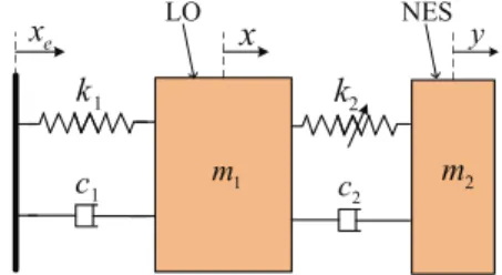
To overcome this limitation, an innovative nonlinear ab-sorber named Nonlinear Energy Sink (NES) has been pro-posed recently [7]. This type of absorber is characterized by a secondary mass strongly coupled via a nonlinear stiff-ness to the primary system that needs to be protected (see Fig. 1). Because of the strong (non-linearizable) nonlinear-ity, irreversible Targeted Energy Transfer (TET) from the main structure to the secondary mass is achieved, enabling
1 m m2 NES LO 1 k 1 c 2 k 2 c
x
y e xthe NES to be effective in a broad band of frequencies [8]. Mastering the nonlinearity is a key element for obtaining the optimum performance of a NES. Depending on the type of nonlinearity, a NES can be classified as a cubic NES [9, 10], a vibro-impact NES [11], a piece-wise NES [12] or a rota-tional NES [13]. As far as the cubic NES is concerned, it has been shown that this configuration is most effective at moder-ate–energy regimes [6]. However, in practice, it is difficult to obtain cubic stiffness without a linear part. In our recent ap-proaches, the essential cubic stiffness was mostly achieved by adopting the construction of two linear springs with no pretension. Due to self-geometric nonlinearity, the springs stretch in tension, thus creating the cubic force [9, 10]. How-ever, this classical type of device cannot effectively profit from spring compression and extension, and the result is a large vertical structure attached to the main system. Addi-tion of a relatively weak nonlinear stiffness existing at the beginning extension, leads to the whole cubic term being ap-proximated to a linear term. Therefore, implementing a cubic stiffness element in practice is still an important issue if the applications of NES are to be broadened.
Recently, physical determination of the nonlinear force-displacement characteristics have been mainly based on non-linear springs or variable stiffness mechanisms. Jutte and Kota [14, 15] developed a nonlinear spring that enabled indi-vidual beam segments to vary their effective stiffness as the spring deformed. Wu and Lan [16] proposed a linear variable stiffness mechanism with preloaded curved beams. S¨onmez and Tutum [17, 18] introduced a compliant bistable mech-anism design by changing the relative stiffness of flexible beams. Chen and Lan [19] designed an adjustable constant force mechanism for adaptive end effector operations. For these mechanisms, a key issue to be satisfied for a NES is that the linear part of the force-displacement characteristics should be very small so as to ensure that the NES can adapt itself to the frequency of any primary system [20].
With this in mind, the main objective of the work pre-sented here is to provide a generalized methodology to de-sign a novel NES with nonlinear spring and variable stiff-ness mechanism, so that it can be tuned over a range of ex-citation. The structure of the article is as follows: the first section is devoted to the design criterion for a cubic NES un-der a given primary system specification. The next section is dedicated to the theoretical design, including the design of conical spring and negative stiffness mechanism, and iden-tification of the NES system. In the third section, a sensi-tivity analysis is carried out with respect to the adjustment differences of the springs and experimental verifications are studied. Finally, some concluding remarks are proposed.
2 Design criterion for cubic NES 2.1 Dynamic modeling
The dynamic modeling presented here is based on Ref-erences [10, 21, 22]. The system of a harmonically excited linear oscillator (LO) strongly coupled with a cubic NES is illustrated in Fig. 1. The objective here is to apply the asymp-totic method used in the above papers to obtain a possible
design optimization criterion, and thus find the best tuned parameters of the NES. The equations of motion are as fol-lows:
(
m1x¨+ k1x1+ c1x+ c˙ 2( ˙x− ˙y) + k2(x − y)3= k1xe+ c1x˙e
m2y+ c¨ 2( ˙y− ˙x) + k2(y − x)3= 0
(1) where x, m1, c1, k1 and y, m2, c2, k2are the displacement,
mass, damping and stiffness of the LO and the cubic NES respectively and the dots denote differentiation with respect to time. The imposed harmonic displacement xeis expressed
as: xe= G cos(ωt).
After rescaling, the system of equations (1) can be re-duced to the dimensionless form:
( ¨
x+ x + ελ1x˙+ ελ2( ˙x− ˙y) + εK (x − y)3= εF cos Ωτ
ε ¨y+ ελ2( ˙y− ˙x) + εK (y − x)3= 0
(2)
where the term containing ε2is so small that can be elimi-nated. The corresponding physical parameters are expressed as follows: ε =m2 m1 , ω02= k1 m1 , K= k2 m2ω02 , λ1= c1 m2ω0 , λ2= c2 m2ω0 , F=G ε, Ω = ω ω0 , τ = ω0t (3)
New variables representing the displacement of the cen-ter of mass and the incen-ternal displacement of the cubic NES are introduced as follows:
v= x + εy, w= x − y (4) Substituting Eqs. (4) into Eqs. (2):
¨ v+ ελ1 ˙ v+ ε ˙w 1 + ε + v+ εw 1 + ε = εF cos Ωτ ¨ w+ ελ1 ˙ v+ ε ˙w 1 + ε + v+ εw 1 + ε + λ2(1 + ε) ˙w +K (1 + ε) w3= εF cos Ωt (5)
The system is studied in the vicinity of the 1:1 reso-nance, where both the LO and the NES execute the time-periodic oscillations with identical frequency Ω. To obtain the analytical periodic solution, two new complex variables are introduced:
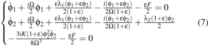
Substituting Eqs. (6) into Eqs. (5) and keeping only the secular term containing eiΩτ yields the following slowly modulated system: ˙φ1+iΩ2φ1+ελ12(1+ε)(φ1+εφ2)−i(φ2Ω(1+ε)1+εφ2)−εF2 = 0 ˙φ2+iΩ2φ2+ελ12(1+ε)(φ1+εφ2)−i(φ2Ω(1+ε)1+εφ2)+λ2(1+ε)φ2 2 −3iK(1+ε)φ22¯φ2 8Ω3 −εF2 = 0 (7) 2.2 Analytical treatment
The activation of energy pumping is efficient for the tar-geted energy transfer of NES. To predict the mechanism, a topological structure of a slow invariant manifold (SIM) is used in the following form:
N102 = (1 + λ22)N202 − 3K 2 N 4 20+ 9K2 16 N 6 20 (8)
where N10, N20 represent the amplitude of φ1and φ2 on a
slow time scale. The two extrema of SIM are described as:
N2,i= 2 3 r (2 ± q 1 − 3λ22)/K i= 1, 2 (9)
A strongly modulated response (SMR) and the corre-sponding projection in the SIM are presented in Fig. 2. The quasi-periodic response with slow variation of the ampli-tudes of both oscillators is observed. In this regime, the procedure of TET can be classified as follows: (1) nonlin-ear beating, where a small amplitude of NES corresponds to the growth of LO amplitude; (2) transient resonance capture, where the NES irreversibly extracts the energy from the LO;
(3) escape from resonance capture, the NES crosses the bi-furcation and is quickly attracted to the low branch of SIM, which leads to a jump down for the energy of the NES. This SMR regime demonstrates the irreversible targeted energy transfer from LO to NES [23], which suppresses energy more efficiently than a steady state response.
With these two extrema of SIM (N21 and N22) located
at the boundary of SMR and stable periodic response, the excitation threshold of the SMR can be obtained and written as:
Gic=
εN2,i(9λ1K2N2,i4 − 24λ1KN2,i2 + 16(λ1+ λ2+ λ1λ22)) 4q9K2N4
2,i− 24KN2,i2 + 16 + 16λ22
(10) The detailed description of Eq. (8) and Eq. (10) are given in [10,21]. When the excitation amplitude is with the interval [G1c, G2c], SMR can be produced. Yet this is not sufficient
to ensure the activation of SMR regimes; another interact-ing factor is the excitation frequency. To explain its influ-ence, the stability of the frequency response function (FRF) is analyzed. Here, a detuning parameter σ representing the nearness of the excitation frequency ω to the reduced natural frequency of the LO is introduced:
Ω = 1 + εσ (11)
The fixed points of the FRF correspond to the periodic solutions of the system. Under the 1:1 resonance hypothesis, the solutions of fixed points can be obtained by equating the derivatives of Eq. (7) in the following form:
˙φ1= ˙φ2= 0 ⇒ φ1(τ) = φ10, φ2(τ) = φ20 (12) 0 1 2 3 4 5 −10 0 10 v (mm) 1 2 0 1 2 3 4 5 −20 0 20 w (mm) t (s) 3 0 5 10 15 20 25 30 4 5 6 7 8 9 10 11 N 20 (mm) N 10 (mm) 1 2 3 N 21 N 22
(a)
(b)
Fig. 2. Cubic NES under periodic forcing with parametersK= 3000,λ1= 0.6,λ2= 0.3,ε = 0.01,G= 0.2 mmand initial conditions
x0= 0,x˙0= 0,y0= 0andy˙0= 0. (a) time-displacement of LO and NES. (b) SIM structure and trace between LO and cubic NES: red curve represents the transient projected motion.
By introducing Eq. (12) into Eq. (7), a system of com-plex algebraic equations is obtained. After several algebraic operations, the system is deduced as:
α3Z203 + α2Z220+ α1Z20+ α0= 0, Z20= |φ20|2 φ10= iεφ20 (1 + ε) (1 + εσ)− ε2λ1φ20 1 + ε +εF+iε 2 λ1F(1+εσ) i(1+εσ)+ ελ1 1 + ε− i (1 + ε) (1 + εσ) (13) where coefficients αi depend on the system parameters and
excitation parameters. The first equation of Eq. (13) is a cu-bic polynomial that can be resolved analytically, so as to ob-tain the fixed points. To determine the stability, small pertur-bations are introduced as follows:
φ1= φ10+ ρ1, φ2= φ20+ ρ2 (14)
By substituting Eq. (14) into Eq. (7), the linearization model with the Jacobian matrix is obtained:
˙ρ1 ˙ρ2 ¯˙ρ1 ¯˙ρ2 = M11εM21 0 0 M22 M22 0 M24 0 0 M¯11ε ¯M21 0 M¯24 M¯21 M¯22 ρ1 ρ2 ¯ρ1 ¯ρ2 (15) where M11= −i(1+ε)2 − ελ1 2(1+ε)+ i 2(1+ε)(1+εσ) M21= −2(1+ε)ελ1 +2(1+ε)(1+εσ)i M22=3i(1+ε)Kφ20 ¯φ20 4(1+εσ)3 − λ2(1+ε) 2 +2(1+ε)(1+εσ)iε −i(1+εσ)2 − ε2λ1 2(1+ε) M24= 3i(1+ε)Kφ2 20 8(1+εσ)3 (16)
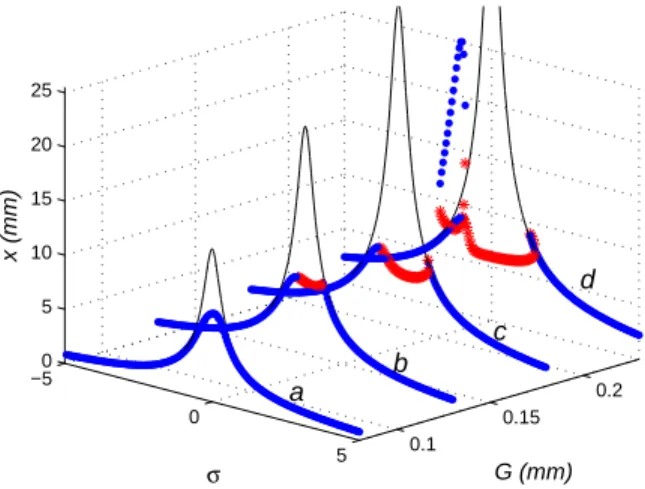
By computing the root of the polynomial characteristic equation, the stability of the fixed points is deduced. If a real root crosses the left-half complex plane, the fixed point is un-stable. Fig. 3 compares the FRF between the system with a cubic NES and without a NES. The maximum amplitude of the axial displacement of the primary system is plotted on the vertical axis as a function of the amplitude G and frequency σ of the excitation. With the addition of a NES, the normal model of the LO becomes nonlinear and varies for different types of energy input. When the energy is low and not suffi-cient to activate the NES, the resonance peak of the LO does not vanish completely (see curve a). For a relatively higher excitation, as shown in curves b and c, the energy pumping of the NES is activated in the unstable area. SMR regimes are possibly produced. As the excitation amplitude is increased still further to G = 0.23 mm (see curve d), the band of fre-quency for SMR becomes larger. However a high amplitude
0.1 0.15 0.2 −5 0 5 0 5 10 15 20 25 G (mm) σ x (mm) a b d c
Fig. 3. Frequency response function (FRF) of LO with cubic NES (points) and without NES (thin line) in different types of excitation:
(a) G = 0.08 mm; (b) G = 0.13 mm; (c) G = 0.18 mm; (d) G= 0.23 mm. The blue points and the red crosses represent stable and unstable fixed points respectively.
detached resonance tongue appears on the left of the main backbone branch, which reduces the efficiency of the control and can be dangerous for the system.
2.3 Criterion for efficient energy pumping
From the FRF analysis, the aim of a design criterion should be first to ensure that energy pumping of the NES ab-sorber is activated and second to avoid the resonance tongue under a given primary system. For this, the effect of nonlin-ear stiffness K and excitation G is analyzed. The maximum amplitude of the FRF is calculated and presented in Fig. 4(a). As the nonlinear stiffness is larger, the resonance tongue oc-curs more easily at low excitation. In Fig. 4(b), as the exci-tation is fixed, an optimal nonlinear stiffness located at the critical resonance tongue position can be found, where the amplitude of the LO is minimum. In Fig. 4(c), as the nonlin-ear stiffness is fixed, the maximum amplitude of the LO will not be larger than the value at this critical point. Thus, the critical position for the appearance of the resonance tongue is studied.
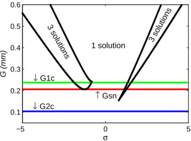
Fig. 5 shows the multiplicity of the periodic solution of the system in Eq. (13). Where the boundary separating single and triple solutions corresponds to the saddle-node bifurca-tion, G1c and G2c represent the threshold of the SMR, Gsn
represents the boundary where three periodic solutions oc-cur in the left of the main resonance frequency. When the excitation is inside the zone [G1c, Gsn], no resonance tongue
occurs and the SMR is probably produced. Therefore, once the parameters of the NES are fixed, the value of Gsncan be
determined as the maximum amplitude of excitation, so as to avoid the occurrence of a resonance tongue.
In Fig. 6, the critical excitation amplitudes are presented as a function of the nonlinear stiffness. As can be seen, the width of the SMR zone decreases as nonlinear stiffness
in-0 0.1 0.2 0.25 2000 2500 3000 3500 4000 0 10 20 30 40 G (mm) (a) K x m (mm) 20000 2500 3000 3500 4000 10 20 30 K x m (mm) (b) G= 0.205 mm 0 0.05 0.1 0.15 0.2 0.25 0 20 40 G (mm) xm (mm) (c) K= 3000
Fig. 4. Maximum amplitude of LO with the variation of (a) nonlinear stiffness and excitation amplitude; (b) nonlinear stiffness; (c) excitation amplitude. Each point is extracted from the maximum amplitude of FRF.
creases. The characteristic points a, b, c and d at K = 3000 show good agreement with the behavior of the system in Fig. 3, which demonstrates that the critical amplitudes of excitation can predict the response regimes well at different excitations.
Based on the above discussion, for a given primary sys-tem, the optimal design for a NES system is dependent on the maximum amplitude of excitation. The design parame-ter should be chosen to avoid a detached resonance tongue in the vicinity of the natural frequency and allow strongly mod-ulated response at the same time. An illustration for choos-ing the tuned parameter of a cubic NES is given in Table 1, here the mass ratio, stiffness and damping of the LO, and the damping of the NES are fixed. The corresponding tuned pa-rameters of nonlinear stiffness K are listed for different maxi-mum amplitudes of excitation (using the Gsncurve of Fig. 6).
With this value, the amplitude of the LO is minimum and no resonance tongue exists in a range of frequencies. The next section presents the design of a tuned NES with the proposed design criterion. −5 0 5 0.1 0.2 0.3 0.4 0.5 0.6 σ G (mm) 3 solutions 3 solutions 1 solution ↓ G1c ↓ G2c ↑ Gsn
Fig. 5. Evolution of the multiplicity of periodic solutions for the sys-tem with parametersK= 3000,λ1= 0.6,λ2= 0.3,ε = 0.01.
Table 1. Parameters of the tuned NES
Reduced parameters ε 1% λ1 0.6 λ2 0.3 K Ksn Kas a function of G G(mm) K G(mm) K 0.291 1500 0.205 3000 0.252 2000 0.191 3500 0.226 2500 0.178 4000 3 Theoretical design 3.1 Conical spring design
Due to its self-nonlinearity, a conical spring has the ad-vantage of providing variable spring rates and varying nat-ural frequencies. For this work, two conical springs with
2000 3000 4000 0 0.1 0.2 0.3 K G (mm) ↓ G1c ↓ G2c ↑ Gsn a b c d
Fig. 6. Critical excitation amplitude as a function of the nonlinear stiffness,λ1= 0.6,λ2= 0.3,ε = 0.01.
0 10 20 30 40 50 0 20 40 60 80 Force (N) Displacement (mm) O T C
Fig. 7. Force characteristic of conical spring ,Trepresents the tran-sition point between linear and nonlinear phase.
a constant pitch and a constant coil diameter were adopted. The detailed design of the conical springs has been achieved in [24, 25] so that the springs do not buckle at large deflec-tions [26]. Considering the strong nonlinearity and lower installation height, the shape of a telescoping spring was used [27].
The force characteristic of a conical spring with a con-stant pitch can be separated into a linear and a nonlinear part. To distinguish the two phases, three particular points are in-troduced, as shown in Fig. 7: point O corresponds to the spring free state, point T is the transition point where the nonlinear behavior starts, and point C represents the state of maximum compression.
In the linear phase (from point O to point T), the largest coil is free to deflect like the other coils, so the force-displacement relation is linear and the stiffness is expressed as:
R= Gd4
2na(D21+D22)(D1+D2) (17)
In the nonlinear regime (from point T to point C), the first elementary part of the largest coil has reached its max-imum physical deflection. It starts to be a non-active ele-ment of the spring. During the second compression regime, the number of active coils decreases continuously, leading to a gradual increase of the spring stiffness. The force-displacement (F-u) relation can be described by:
u(F) = 2FD41na Gd4(D 2−D1)[(1 + ( D2 D1− 1) · nf na) 4− 1] +(La− Ls)(1 − nf na) (18)
where d, na, nf, La, Ls, G represent the wire diameter,
num-ber of active coils, numnum-ber of free coils, initial active length, solid length of active coils and shear modulus of elasticity, respectively, and D1 and D2 represent the mean diameter
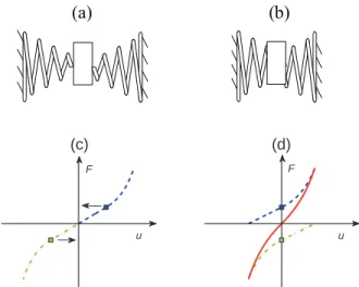
(a) (b)
(c) (d) u F u F
Fig. 8. State and corresponding force of two conical springs (green and blue): (a)(c) at original length; (b)(d) pre-compressed at the tran-sition point. The red curve represents the composed force.
of the smallest and largest coils. A detailed description of Eq. (17) and Eq. (18) can be found in [24].
To benefit from the nonlinear performance of the coni-cal spring, a symmetriconi-cal connecting type of spring is pro-posed, as shown in Fig. 8(a). However, this configuration has the piecewise stiffness of a linear and a nonlinear part. To skip the linear phase, a method of pre-compressing the spring at the transition point is proposed and is presented in Fig. 8(b). By changing the initial origin point, the behaviors of two conical springs can belong one to the linear and one to the nonlinear regime simultaneously. By combining the two spring curves, the composed stiffness curve is obtained (see Fig. 8(d)). It can be clearly observed that the new curve is smooth and no longer piecewise.
To analyze the internal polynomial components, the method of polynomial fitting was used, and the new force-displacement relation was written as:
F= a1u+ a2u2+ a3u3+ O(u4) (19)
Because of the superposition of linear and nonlinear parts, the linear term of Eq. (19) was hard to eliminate, yet it was possible to make the value of the square term a2u2small.
After optimizing the parameters of the conical spring (the mean diameters D1and D2), the polynomial components
were obtained and are presented in Fig. 9. It can be observed that the curve of the cubic and linear terms is close to the original curve F(u), which means that the contribution of the square term was small enough to be almost neglected.
3.2 Negative stiffness mechanism
To eliminate the proposed linear term, adding a new term having the negative stiffness in the translational direc-tion seemed to be a way forward. For this, a negative stiffness
−20 −10 0 10 20 −60 −30 0 30 60 Force (N) Displacement (mm) Original curve Cubic+linear Cubic+square Cubic term
Fig. 9. Polynomial components of the two optimized conical springs
mechanism was implemented from two cylindrical compres-sion springs [28]. To obtain the required negative stiffness, the ends of the springs are able to rotate and the initial axes of the springs are perpendicular to the main motion axis, as shown in Fig. 10.
Based on the Taylor expansion, the force-displacement relation of pre-compression at the length lpcan be expressed
as:
f = 2kllp· u − k(l+lp)
l3 · u3 (20)
By adding the force of two conical springs to the force of negative stiffness mechanism, the composed force of the NES system is obtained:
F= (a1− 2klp
l) · u + (a3+ k (l+lp)
l3 ) · u3 (21)
As can be seen from Eq. (21), if a1= 2klp/l, the linear
component can be counterbalanced by the negative stiffness mechanism. In this case, only the pure cubic term of the equation will be left, and its coefficient will be larger with the addition of two linear springs.
f
k
k
0l
l
pl
u
FP
(a)
(b)
(c)
t SFig. 10. Schematic of NES system: (a) negative stiffness mecha-nism (b) conical spring (c) the composed system
Fig. 11. Assembly of NES system. xandycorrespond to the dis-placement of LO and NES respectively.
4 Identification of NES system
Based on the proposed methods, a small-sized NES sys-tem providing strongly nonlinear stiffness was designed and the assembly drawing is presented in Fig. 11. The compo-nent parts are spherical plain bearings, a linear guide, two conical springs, two linear springs and a NES mass. It is important to highlight that the distance between each spring and the NES mass is adjustable so that a suitable force shape can be reached.
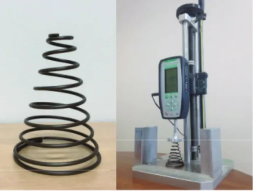
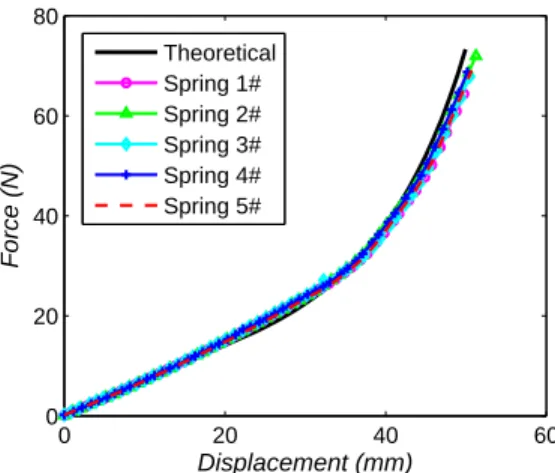
To obtain the performance of the conical spring, an iden-tification study was performed. The manufactured conical spring and the measuring equipment are presented in Fig. 12. The force gauge has a 500 N capacity with 0.1% accuracy and 0.04 N resolution, the handle allows a stroke of 2 mm per revolution, the displacement transducer with digital dis-play has a resolution of 0.01 mm. The results of tests on five conical springs are presented in Fig. 13. As expected, corre-spondence is good between the experimental results and the theoretical curve.
The NES system can be divided in several parts: a part attached to the primary system, a NES part and the springs. The NES part includes the mass of the sliding part, the spher-ical plain bearing, and the support base of the linear and con-ical springs. For dynamic calculations, as the NES mass (ma)
is very small, the inertia of the springs is not negligible and has to be considered. To a rough approximation, considering
0 20 40 60 0 20 40 60 80 Force (N) Displacement (mm) Theoretical Spring 1# Spring 2# Spring 3# Spring 4# Spring 5#
Fig. 13. Experimental force-displacement relation of conical springs
the spring as a beam and neglecting axial inertia, the kinetic energy of the NES mass and the linear spring is written as follows:
TNES=R0l0ρs(lx
0y)˙
2dx+1
2m2y˙2 (22)
where ρs= ms/l0is the mass density of the spring. Thus the
effective mass of a linear spring is calculated:
ˆ
ms= ms/3 (23)
For the conical spring, the effective mass of ˆmc can be
expressed as [29]: ˆ mc= 2mc 1 10(1−β10)−13β4(1−β6)+12β8(1−β2) (1−β4)2(1−β2) , β = D2 D1 (24)
Thus, the total effective mass of the NES for dynamic equations is obtained:
m2= ma+ 2 ˆms+ 2 ˆmc (25)
Fig. 14. NES system with linear springs of large mean diameter
Fig. 15. Details of the experimental setup and measuring system
Fig. 14 illustrates an installed NES system with linear springs of large mean diameter. Here, it is important to note that a linear spring with small mean diameter has a tendency to buckle when its deflection is large. Therefore, linear springs with large mean diameter were chosen. The final spring test for the NES system is shown in Fig. 15. The NES is held by a ring so that it can be connected to the in-ternal load cell of the force gauge. With this experimental setup, the force can be measured in both compression and extension. Fig. 16 shows the force-displacement relation of the NES that was designed. As can be seen, the experimen-tal curve and the theoretical cubic curve corresponded well. Thus it can be concluded that combining conical springs and a negative stiffness mechanism is a feasible way to produce pure cubic stiffness. Enough pre-compressed length should be reserved in both the conical and the linear springs to en-able the anticipated nonlinearity to be obtained. Moreover, the effective mass of the springs and buckling of the nega-tive stiffness mechanism should not be neglected during the design procedure.
5 Sensitivity analysis
A sensitivity analysis of NES system is addressed in this section, considering the precision of the installation and quantifying the uncertainty [30]. The performance of the
−20 −10 0 10 20 −20 −10 0 10 20 Displacement (mm) Force (N) Experimental Theoretical
1
g
2g
1h
h2Fig. 17. Differences of the adjustment length for conical springs (γi) and linear springs (ηi)
NES relies on the given primary system specification, which is presented in Table 2. Here, the maximum excitation am-plitude is fixed as G = 0.205 mm, and the system parameters are related to the reduced parameters of Table 1. Thus the tuned parameter of nonlinear stiffness can de determined as K= 3000, with the physical value of k2= 3 × 10⁶N/m3. To
obtain this value, both the conical springs and the cylindrical compression springs need to be pre-compressed to the antic-ipated length, with ¯St= 24.8 mm and ¯lp= 11.9 mm.
How-ever, it is hard to control the coefficients a0, a1, a2and a3at
the anticipated value since differences exist in practice. To analyze their influence, differences of the adjustment length for conical and linear springs were selected as the variables, defined as γiand ηi, respectively (see Fig. 17). Then the real
adjustment lengths are:
St,i= ¯St,i+ γi, lp,i= ¯lp,i+ ηi, i= 1, 2 (26)
Thus, the system of equations (2) can be written in the following form: ( ¨ x+ x + ελ1x+ ελ˙ 2( ˙x− ˙y) + εζ · f (x − y) = εF cos Ωτ ε ¨y+ ελ2( ˙y− ˙x) − εζ · f (x − y) = 0 (27)
Table 2. Parameters of the designed NES
Tuned parameters G 0.205 mm K 3000 System parameters m1 5 kg m2 50 g k1 1 × 10⁵N/m k2 3 × 10⁶N/m3 c1 4 Ns/m c2 2 Ns/m Anticipated parameters ¯ St 24.8 mm ¯lp 11.9 mm a0 0 N a1 0 N/m a2 −4.4 N/m2 a3 2.97 × 10⁶N/m3
where the corresponding parameters are expressed as:
f(x − y) = a0+ a1(x − y) + a2(x − y)2+ a3(x − y)3
ζ = 1/(m2ω20)
(28)
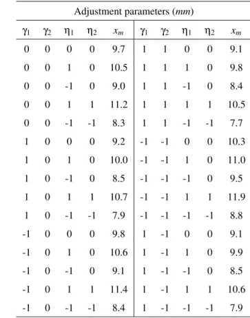
Based on Eq. (27), a sensitivity analysis for the stiff-ness of the NES is summarized in Table 3, where the vari-ables γi and ηi are selected in the interval [−1, 1] mm, the
objective xm is extracted from the maximum amplitude of
the LO in the numerical FRF. As can be seen, in the vicinity of the frequency of the resonance, no resonance tongue oc-curs, and all the maximum amplitudes of the LO are smaller than 12 mm. In comparison with the maximum amplitude of the LO without NES (36.2 mm), the amplitude of the LO is decreased by more than 67% with the help of NES. Another factor that needs to be considered is the damping of the NES. With the variation of the adjustment lengths, this value could also be changed. A sensitivity analysis for the NES damp-ing is presented in Table 4, where the stiffness of the NES is fixed and the damping c2is selected in the variation
inter-val [−15, 15]%. The maximum amplitudes of LO are close to each other, which means that the NES is not sensitive to differences of damping.
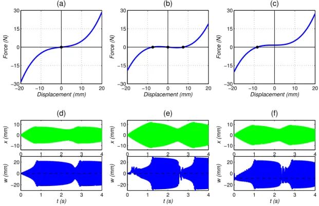
Three particular examples of Table 3 were extracted and the corresponding nonlinear force versus the response of LO and NES were calculated. The results are presented in Fig. 18, where positive stiffness, negative stiffness and
un-Table 3. Sensitivity analysis for the stiffness of NES
Adjustment parameters (mm) γ1 γ2 η1 η2 xm γ1 γ2 η1 η2 xm 0 0 0 0 9.7 1 1 0 0 9.1 0 0 1 0 10.5 1 1 1 0 9.8 0 0 -1 0 9.0 1 1 -1 0 8.4 0 0 1 1 11.2 1 1 1 1 10.5 0 0 -1 -1 8.3 1 1 -1 -1 7.7 1 0 0 0 9.2 -1 -1 0 0 10.3 1 0 1 0 10.0 -1 -1 1 0 11.0 1 0 -1 0 8.5 -1 -1 -1 0 9.5 1 0 1 1 10.7 -1 -1 1 1 11.9 1 0 -1 -1 7.9 -1 -1 -1 -1 8.8 -1 0 0 0 9.8 1 -1 0 0 9.1 -1 0 1 0 10.6 1 -1 1 0 9.9 -1 0 -1 0 9.1 1 -1 -1 0 8.5 -1 0 1 1 11.4 1 -1 1 1 10.6 -1 0 -1 -1 8.4 1 -1 -1 -1 7.9
Table 4. Sensitivity analysis for the damping of NES
Adjustment parameters
c2(Ns/m) 1.7 1.8 1.9 2.0 2.1 2.2 2.3
xm(mm) 9.5 9.6 9.7 9.7 9.8 9.8 9.9
symmetrical stiffness are observed, according to the exam-ple. In Fig. 18 (a) and (d), as the pre-compressed lengths ηi are smaller than the anticipated value, the stiffness curve
is no longer pure cubic and a positive linear stiffness is pro-duced. It is interesting to observe that the amplitude of the LO is lower here than in the other cases, which indicates that adding a small positive stiffness may help with vibration mit-igation under a certain excitation. In Fig. 18 (b) and (e), the force curve has two stable equilibria and one unstable equi-librium. Between the two stable equilibria, the stiffness is negative and a bistable NES is obtained. In this case, the amplitude of the LO is increased, and the range of excitation amplitude for efficient TET is broader [31]. This suggests that, as the springs of this prototype are fixed for engineer-ing applications, adjustengineer-ing the pre-compressed length would provide an alternative way to increase the band in which ex-citation amplitude is robust. In Fig. 18 (c) and (f), the equi-librium of the force curve is no longer located at the center but shifts to the left. Although the stiffness curve is unsym-metrical, the energy pumping between NES and LO is still activated, leading to a significant decrease of the amplitude
of the LO. Therefore, this type of NES can work robustly with differences in the adjustment lengths.
6 Experimental verifications
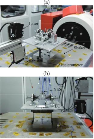
The aim of the experimental tests was to obtain the non-linear frequency response function of the system around the 1:1 resonance, so as to verify the efficiency of the designed NES. The experimental setup is presented in Fig. 19 and con-sists of an LO with an embedded NES. For the LO, a weakly nonlinear behavior exists but does not affect the purpose of the tests. For the setup, the periodic excitation is provided by a 10 kN electrodynamic shaker. The raw signals are recorded using a digital oscilloscope and a bandpass filter is applied to correct biases and suppress high frequency noise. The dis-placement of the LO and NES, and the acceleration of the shaker are measured by two contactless laser displacement sensors and an accelerometer, respectively.
The frequency response function of LO obtained with the sweeping frequency test is presented in Fig. 20 (a), where the thick blue and the thin red lines represent the response of the LO with and without NES, respectively. It can be seen that the original peak of the FRF has vanished and the de-tached resonance tongue no longer exists. The RMS value of LO amplitude is obviously decreased with the vibration mitigation of the NES. In the response of the LO, the dy-namical flow for different values of the frequency might be attracted either to a smooth zone, or alternatively, to a num-ber of discontinuities (range of non-monotonicity). The
for-−20 −10 0 10 20 −30 −15 0 15 30 Force (N) Displacement (mm) (a) −20 −10 0 10 20 −30 −15 0 15 30 Force (N) Displacement (mm) (b) −20 −10 0 10 20 −30 −15 0 15 30 Force (N) Displacement (mm) (c) 0 1 2 3 4 −10 0 10 x (mm) (d) 0 1 2 3 4 −20 0 20 w (mm) t (s) 0 1 2 3 4 −10 0 10 x (mm) (e) 0 1 2 3 4 −20 0 20 w (mm) t (s) 0 1 2 3 4 −10 0 10 x (mm) (f) 0 1 2 3 4 −20 0 20 w (mm) t (s)
Fig. 18. The nonlinear NES force versus the response of LO and NES withG= 0.205 mm,σ = −0.2: (a)(d) positive linear stiffness,
γ1= γ2= 1,η1= η2= −1; (b)(e) negative linear stiffness,γ1= γ2= −1,η1= η2= 1; (c)(f) unsymmetrical stiffness,γ1= 1,γ2= −1,
!"
#"
$%!&'( )*$ +, +!-'( .//'0'(12'3'(Fig. 19. Experimental setup: (a) global view of the system and (b) detailed view of LO and NES
mer corresponds to the steady state response; the latter cor-responds to the unstable fixed points, where a Strongly Mod-ulated Response (SMR) occurs. A detailed view of the SMR is presented in Fig. 20 (b). Where the displacements of the LO increase and decrease alternately with the cyclical acti-vation and deactiacti-vation of the NES. In this process, targeted energy transfer (TET) occurs and the energy is irreversibly dissipated from the LO to the NES. Thus it can be concluded that this NES can produce energy pumping and is efficient to protect the primary system in a large band of resonance frequencies.
7 Conclusion
In this paper, the design theory and sensitivity analysis of a tuned NES attached to a harmonically forced linear os-cillator is investigated. Firstly, a design criterion intended to find the tuned parameter of nonlinear stiffness for a given primary system specification is proposed. The aim of this cri-terion is to avoid the detached resonance tongue in the vicin-ity of the resonance frequency and allow SMR at the same time. To this end, a combined method with slow invariant manifold (SIM), threshold of SMR and stability of the fixed points is studied theoretically. Frequency response functions (FRF) are calculated when the different parameters (i.e. am-plitude and frequency of excitation, nonlinear stiffness) are varied and explain the behavior of the NES well. As a result,
15 16 17 18 19 0 0.1 0.2 0.3 f (Hz) F R F
(a)
LO LO+NES 10 12 14 16 18 20 −8 −4 0 4 8 t(s) A (m m )(b)
NES LOFig. 20. Experimental results: (a) frequency response curve of LO with (blue) and without (red) the designed NES; (b) Strongly Modu-lated Response of LO (blue) and NES (green).
an optimal nonlinear stiffness is obtained, so as to tune the NES be activated and produce the efficient TET. Secondly, a novel NES design leading to a strongly cubic stiffness is pre-sented. Two conical springs are specifically sized to provide the polynomial components with only linear and cubic terms. To eliminate the linear term, a concept of negative stiffness mechanism is implemented by two cylindrical compression springs. A small-sized NES system providing strongly non-linear stiffness is developed. To validate the concept, iden-tification of the force-displacement relation is performed. A good correlation between the theoretical and the experimen-tal result is observed. Finally, a sensitivity analysis is car-ried out with respect to adjustment differences of the springs and an experiment involving the whole system embedded on an electrodynamic shaker is performed. The results show that this type of NES can avoid the resonance tongue and still provide energy pumping with the differences of stiffness and damping. Furthermore, by adjusting the pre-compressed length of springs, this NES can be tuned to work robustly over a range of excitation, which makes it preferable for the application of passive vibration control.
References
[1] Jiang, J., and Iwai, Y., 2009. “Improving the b-spline method of dynamically-compensated cam design by minimizing or restricting vibrations in high-speed cam-follower systems”. ASME J. Mech. Des., 131(4), p. 041003.
[2] Kim, S., Dean, R., Flowers, G., and Chen, C., 2009. “Active vibration control and isolation for mi-cromachined devices”. ASME J. Mech. Des., 131(9), p. 091002.
[3] Trimble, A. Z., Lang, J. H., Pabon, J., and Slocum, A., 2010. “A device for harvesting energy from rotational vibrations”. ASME J. Mech. Des., 132(9), p. 091001. [4] Okwudire, C. E., 2012. “Reduction of torque-induced
bending vibrations in ball screw-driven machines via optimal design of the nut”. ASME J. Mech. Des., 134(11), p. 111008.
[5] Moeenfard, H., and Awtar, S., 2014. “Modeling ge-ometric nonlinearities in the free vibration of a planar beam flexure with a tip mass”. ASME J. Mech. Des., 136(4), p. 044502.
[6] Vakakis, A. F., Gendelman, O. V., Bergman, L. A., Mc-Farland, D. M., Kerschen, G., and Lee, Y. S., 2008. Targeted Energy Transfer in Mechanical and Structural Systems, Vol. 156. Springer Science & Business Media, Berlin.
[7] Vakakis, A. F., and Gendelman, O. V., 2001. “Energy pumping in nonlinear mechanical oscillators: part ii: resonance capture”. J. Appl. Mech., 68(1), pp. 42–48. [8] Lee, Y., Vakakis, A. F., Bergman, L., McFarland,
D., Kerschen, G., Nucera, F., Tsakirtzis, S., and Panagopoulos, P., 2008. “Passive non-linear targeted energy transfer and its applications to vibration absorp-tion: a review”. Proc. Inst. Mech. Eng. Part K J. Multi-body Dyn,222(2), pp. 77–134.
[9] Gourdon, E., Alexander, N., Taylor, C., Lamarque, C., and Pernot, S., 2007. “Nonlinear energy pumping un-der transient forcing with strongly nonlinear coupling: Theoretical and experimental results”. J. Sound. Vib, 300(3–5), pp. 522 – 551.
[10] Gourc, E., Michon, G., Seguy, S., and Berlioz, A., 2014. “Experimental investigation and design opti-mization of targeted energy transfer under periodic forcing”. ASME J. Vib. Acoust, 136(2), p. 021021. [11] Gourc, E., Michon, G., Seguy, S., and Berlioz, A.,
2015. “Targeted energy transfer under harmonic forc-ing with a vibro-impact nonlinear energy sink: analyt-ical and experimental developments”. ASME J. Vib. Acoust,137(3), p. 031008.
[12] Lamarque, C.-H., Gendelman, O. V., Savadkoohi, A. T., and Etcheverria, E., 2011. “Targeted en-ergy transfer in mechanical systems by means of non-smooth nonlinear energy sink”. Acta Mechanica, 221(1-2), p. 175.
[13] Sigalov, G., Gendelman, O., Al-Shudeifat, M., Manevitch, L., Vakakis, A., and Bergman, L., 2012. “Resonance captures and targeted energy transfers in an inertially-coupled rotational nonlinear energy sink”.
Nonlinear Dyn.,69(4), pp. 1693–1704.
[14] Jutte, C. V., and Kota, S., 2008. “Design of non-linear springs for prescribed load-displacement func-tions”. ASME J. Mech. Des., 130(8), p. 081403. [15] Jutte, C. V., and Kota, S., 2010. “Design of single,
multiple, and scaled nonlinear springs for prescribed nonlinear responses”. ASME J. Mech. Des., 132(1), p. 011003.
[16] Wu, Y.-S., and Lan, C.-C., 2014. “Linear variable-stiffness mechanisms based on preloaded curved beams”. ASME J. Mech. Des., 136(12), p. 122302. [17] S¨onmez, ¨U., 2007. “Introduction to compliant long
dwell mechanism designs using buckling beams and arcs”. ASME J. Mech. Des., 129(8), pp. 831–843. [18] S¨onmez, ¨U., and Tutum, C. C., 2008. “A
compli-ant bistable mechanism design incorporating elastica buckling beam theory and pseudo-rigid-body model”. ASME J. Mech. Des.,130(4), p. 042304.
[19] Chen, Y.-H., and Lan, C.-C., 2012. “An adjustable constant-force mechanism for adaptive end-effector op-erations”. ASME J. Mech. Des., 134(3), p. 031005. [20] Al-Shudeifat, M. A., 2017. “Nonlinear energy
sinks with nontraditional kinds of nonlinear restoring forces”. ASME J. Vib. Acoust, 139(2), p. 024503. [21] Gendelman, O., Starosvetsky, Y., and Feldman, M.,
2008. “Attractors of harmonically forced linear oscilla-tor with attached nonlinear energy sink i: Description of response regimes”. Nonlinear Dyn., 51(1), pp. 31– 46.
[22] Starosvetsky, Y., and Gendelman, O., 2007. “Attractors of harmonically forced linear oscillator with attached nonlinear energy sink ii: Optimization of a nonlinear vibration absorber”. Nonlinear Dyn., 51(1), p. 47. [23] Starosvetsky, Y., and Gendelman, O., 2008. “Strongly
modulated response in forced 2dof oscillatory system with essential mass and potential asymmetry”. Physica D: Nonlinear Phenomena,237(13), pp. 1719–1733. [24] Rodriguez, E., Paredes, M., and Sartor, M., 2006.
“Analytical behavior law for a constant pitch conical compression spring”. ASME J. Mech. Des., 128(6), pp. 1352–1356.
[25] Paredes, M., 2013. “Analytical and experimental study of conical telescoping springs with nonconstant pitch”. ASME J. Mech. Des.,135(9), p. 094502.
[26] Patil, R. V., Reddy, P. R., and Laxminarayana, P., 2014. “Comparison of cylindrical and conical helical springs for their buckling load and deflection”. Int. J. Adv. Sci. Technol,73, pp. 33–50.
[27] Qiu, D., Seguy, S., and Paredes, M., 2017. “A novel de-sign of cubic stiffness for a nonlinear energy sink (nes) based on conical spring”. In Advances on Mechan-ics, Design Engineering and Manufacturing. Springer, pp. 565–573.
[28] Harne, R., Thota, M., and Wang, K., 2013. “Concise and high-fidelity predictive criteria for maximizing per-formance and robustness of bistable energy harvesters”. Appl. Phys. Lett.,102(5), p. 053903.
mass system free vibration”. J. Sound. Vib, 220(3), pp. 564–570.
[30] Opgenoord, M. M., Allaire, D. L., and Willcox, K. E., 2016. “Variance-based sensitivity analysis to support simulation-based design under uncertainty”. ASME J. Mech. Des.,138(11), p. 111410.
[31] Romeo, F., Sigalov, G., Bergman, L. A., and Vakakis, A. F., 2015. “Dynamics of a linear oscillator coupled to a bistable light attachment: Numerical study”. ASME J. Comput. Nonlinear Dynam.,10(1), p. 011007.