HAL Id: hal-02337493
https://hal.telecom-paris.fr/hal-02337493
Submitted on 29 Oct 2019
HAL is a multi-disciplinary open access
archive for the deposit and dissemination of
sci-entific research documents, whether they are
pub-lished or not. The documents may come from
teaching and research institutions in France or
abroad, or from public or private research centers.
L’archive ouverte pluridisciplinaire HAL, est
destinée au dépôt et à la diffusion de documents
scientifiques de niveau recherche, publiés ou non,
émanant des établissements d’enseignement et de
recherche français ou étrangers, des laboratoires
publics ou privés.
Test Sequence Generation From Formally Verified
SysML Models
Pierre de Saqui-Sannes, Ludovic Apvrille
To cite this version:
Pierre de Saqui-Sannes, Ludovic Apvrille. Test Sequence Generation From Formally Verified SysML
Models. Asia-Pacific Software Engineering Conference (APSEC’2019), Feb 2019, Stuttgart, Germany.
�hal-02337493�
Test Sequence Generation From Formally Verified SysML Models
Pierre de Saqui-Sannes
ISAE-Supaero 10 Avenue Emile blouin
31400 Toulouse, France
Email: [email protected]
Ludovic Apvrille
LTCI, Telecom ParisTech, Universit´e Paris Saclay 46 rue Barrault
75013 Paris, France
Email: [email protected]
Abstract—Test generation has been acknowledged as a cost-prone activity reducing productivity and time to market. The expected benefits of Model Based Systems Engineering include automated generation of test sequences from models. The paper proposes verification solutions for the System Modeling Lan-guage (SysML). In particular, the paper shows how to link test generation to formal verification. The proposed algorithms are implemented by the free software TTool. Two case studies support discussion on conformance and interoperability testing, respectively.
I. INTRODUCTION
The widespread of Model Based System Engineering ap-proaches [1] has encouraged several communities to de-velop their own modelling language. For instance, the Ob-ject Management Group (OMG) [2] and the International Council for Systems Engineering (INCOSE) [3] have jointly developed and standardized the Systems Modeling Language (SysML) [4]. The benefits and potential of using SysML have been acknowledged in several application domains, in particular avionics [5], [6], [27]. SysML is now supported by proprietary [7], [8] and open-source tools like Papyrus1 or TTool2that help automating an important variety of activities (e.g. [9]) throughout the design trajectory of complex systems. One of these activities is test sequence generation, an activity that is cost-prone and time consuming, and therefore worth being automated to reduce time to market of complex systems. Automated test generation from SysML models has already been discussed in [10], [11], [12]. The paper proposes another SysML-approach based on earlier work with the Formal De-scription Technique Estelle [13].
In brief, the reachability graph of the SysML model is com-puted directly from the block instance diagram that defines the architecture of the system and from the state machine diagrams that define the behaviors of the block instances. The transitions of the graph are labelled using the messages exchanged by pairs of block instances. This transforms the reachability graph of the SysML model into a Labeled Transition System. Theories developed for LTS [16] therefore apply, in particular minimization that outputs a quotient automaton computed with respect to an equivalence relation such as Milner’s observational equivalence [17]. Taking a quotient automaton as input, all the paths of maximal size leading to a termination state are computed using the Dijkstra technique (22) to finally
1Papyrus: https://www.eclipse.org/papyrus/ 2TTool: https://ttool.telecom-paristech.fr/
obtain a set a test sequences. Associated algorithms have been implemented in the free and open-source tool named TTool [10].
The paper is organized as follows. Section II introduces SysML and more precisely the block instance and state ma-chine diagrams. Section III presents a verification by abstrac-tion approach for SysML models. Secabstrac-tion IV uses the output of the verification process to generate test sequences. Section V applies the proposed approach to a client/server protocol and discusses interoperability testing. Section VI uses a UAV in charge of taking pictures to address conformance testing. Section VII surveys related work. Section VIII concludes the paper and outlines future work.
II. SYSML
The SysML standard [3] defines nine type of diagrams that may be used inside one model to cover the requirement cap-ture, analysis and design phases in the trajectory of systems. For the test generation approach discussed in the paper, only the design phase is of interest.
During the design phase, one defines the architecture of the system and the behaviors of the blocks the architecture is made up of. The SysML standard defines two architectural design diagrams: the Block Definition Diagram (BDD) and the Internal Block Diagrams (IBD) of the SysML standard. In the paper, we use the version of SysML supported by TTool where the BDD and IBD are merged into one diagram: the Block Instance Diagram (BID). Each block instance has a behavior expressed in the form of a SysML state machine diagram.
A. Block Instance Diagram
A Block Instance Diagram is a tripartite graph with one type of nodes, each one defining a block instance, and two types of relations. First, the ”composition” relation of SysML (black diamond) enables to say that one block instance is made up of one or several block instances. Second, the ”connect” relation connects two ports used for exchanging signals. For simplicity, the below definitions address the ”connect” relation, not the ”composition” one.
Definition: block instance. A block instance is a 4-uple (id, al, ml, pl, isl, osl) where:
• alis an attribute list. The attribute types include Integer, Boolean, Timer, and user-defined Records. An attribute may be defined with an initial value.
• ml is a method list.
• pl is a port list.
• isl is an input signal list.
• osl is an output signal list.
Definition: Block Instance Diagram. A Block Instance Diagram is a 3-uple (Blk, connect, assoc) where:
• Blkis a set of block instances.
• connect is a function Port → Port that connects pairs of ports.
• assoc is a function (BlkxSignal) → (BlockxSignal) that associates one signal of block B1 to one signal of block B2, making it possible to compose the state machines belonging to B1 and B2. Here, the term compose denotes a composition in the usual sense of finite state machine composition, not the composition relation supported de-picted by a black diamond in SysML.
Finally, a Block Instance Diagram depicts the architecture of a system as a graph of interconnected blocks.
B. State Machine Diagram
Each block instance contains one extended state finite state machine that supports states, transitions, attribute settings, in-puts and outin-puts operations on signals, and time manipulation. Definition: State Machine. An extended finite state machine depicted by a SysML state machine diagram is bi-partite graph (s0, S, T ) where
• S is a set of states (s0 is the initial state). • T is a set of transitions.
Definition: State Transition. A transition in a state machine is a 5-uple (sstart, a f ter, condition, Actions, send) where:
• sstart is the initial state of the transition.
• a f ter(tmin,tmax) enables firing the transition after at least between tmin and tmax units of time have elapsed.
• condition is a Boolean expression that conditions the execution of the transition. A condition may use attributes of its corresponding block.
• Actions is a ordered set of action. These actions can be executed only once the transition has been enabled i.e. the a f ter clause has elapsed and the condition equals true.
• send is the final state of the transition.
A state machine cannot contain parallel states, historic state, fork and join states. These behaviors can easily be replaced by counterparts. e.g. using sub-blocks and synchronous signals for each parallel activity.
III. FORMAL VERIFICATION
Adding a state machine to each block instance makes the model an executable one. Interactive simulation enables early checking of the state machines against design errors. It does not necessarily explore the entire state space of the model.
Thus, it heavily depends on the experience of the user of the simulator, or on the random generator of that simulator. Conversely, formal verification relies on mathematics rather than chance.
A. Working Hypothesis
The verification approach discussed in this section requires exploring the state space of the SysML and more precisely generating (a sub part of) the graph of states that may be reached from the initial state of the system. Full generation of the reachability graph of the SysML model explores all the execution paths the system may go through starting from its initial state. The graph enables checking the system against reachability properties (using the model-checker we have integrated into TTool). Also, when a property to investigate is the reachability of a given state, then the graph generation stops as soon as the property is satisfied (on-the-fly model-checking).
As usually, reachability analysis faces the state space explosion problem. Starting from now, the following hypothesis applies: the reachability graph of the SysML model may be entirely built within an acceptable amount of time and memory. B. Labeled Reachability Graph
In this section, we assume the SysML model is composed of one block instance diagram and one state machine diagram per block instance. Other diagrams of the SysML model are ignored since they do not play any role in the reachability graph construction process.
Definition: Labeled Reachability Graph. The Labeled Reachability Graph (LRG) of a SysML model is a 5-uple LRG = (S, Σ, Θ, ∆, s0) where:
• S denotes the countable number of global states of the SysML model
• Σ is a countable set of observable events included in the list of signals exchanged on ports. Thus we have Σ ⊆ ”!”Ao(p) ∪ ”?”Ai(p) ∪ ”!”So(p) ”?”Si(p)) where:
– ”!” and ”?” respectively denote an emission and a reception.
– Ao(p) is an output signal connected to an
asyn-chronous channel.
– Ai(p) is an input signal connected to an
asyn-chronous channel.
– Soand S1are output and input signals connected via
a synchronous channel.
– p denotes a list of attributes of the block to which the signal sending/receiving corresponds.
• Θ is a countable set of internal events, e.g. the assignation of an attribute. Thus we have Θ ⊆ i(a =< expr >) ∨ i() where a is an attribute.
• ∆ ⊆ Sx(Σ ∪ Θ)xS denotes the set of labeled transitions in the reachability graph. A label contains the name of the signal exchanged by one pair of block instances or the identification of the internal action, i.e. i(...). An empty i() transition is sometimes denoted τ.
• s0 denotes the initial state of the SysML model, i.e. the
global state obtained when all the block instances enter their initial states.
Generating the LRG consists in considering all possible transitions from all handled states —this not-yet-handled set contains s0when starting the graph generation—.
For each not yet handled transition t fire-able from a given state s1∈ not − yet − handled, we first create δ ∈ ∆ with
δ = (s1, σ , s2). We then have to compute whether ∃s ∈ S
with s ≡ s2. If this is the case, δ = (s1, σ , s2). Otherwise, s2
is added to S and to the not-yet-handled set. This leads us to define the notion of state and of state equivalence for a SysML model.
Definition: State. The state of a SysML model is defined as S
Sb, Sawhere:
• Sbis the state of block b. The state of a block b is defined
by the value of its attributes al, by one state of its state machine (it can be considered as a pointer to the current state of the state machine of b), and by the value of its clock. Indeed, if we assume a global clock applied to all blocks, we need to use a local clock to remember how much of after clauses has elapsed.
• Sarepresents the state of the signal queue a. There is one
signal queue for each asynchronous communication. The state of a signal queue is characterized by its ordered list of n messages m1(p11, p12, ...), m2(p21, p22, ...), ...).
Definition: State equivalence. Two states s1 and s2 are
said to be equivalent s1≡ s2 if and only if all their state
values are equal.
In terms of tool implementation, the above approach is implemented by the model-checker integrated to TTool. The comparison between states is based on hashing techniques taking into account all elements above listed: state machine pointer, attributes values, local clock, message queues. Finally, contrary to many contributions, we are able to generate LRG directly from SysML model, without the need to use a pivot language. This facilitates the back-tracing to models, and avoids formally proving model transformations. This probably has a performance cost when generating the reachability graphs or more generally studying safety properties.
C. LRG Minimization
The labeled reachability graph of the SysML model may have hundred, thousands and even more states and transitions. Definitely, interpreting such a graph is impossible for Human. Also, the purpose of verification is not to check the entire behavior of the system in one operation. The question of which subset of the system can be defined and checked is then asked. The answer proposed by verification by abstraction is as follows: verification will zoom on a subset of the signals exchanged by pairs of blocks involved in the evolution of the system. To refer to the theories developed for Labeled
Transitions Systems, these signals of interest play the role of observable events. Other signals become de facto invisible events. Transitions involving one signal exchange are labeled by the name of the signal. Other transitions are labeled by τ . The objective of minimizing the Labeled Reachability Graph is to get rid of the transitions labeled by τ and to keep the ones labeled by a signal name. Depending on the equivalence relation, the quotient automaton resulting from the minimization process may still contain τ transitions.
TTool implements a 3-step algorithm:
1) Replace each ignored actions with a τ action.
2) Remove all τ transitions i.e. merging states s1 and s2 when there is a τ transition between the two.
3) Minimize the graph.
The quotient automaton computation algorithm can be sketched as follows. If the first two stages are quite straight-forward from an algorithmic point of view, the minimization itself relies on the identification of coarse blocks, i.e. blocks that are bisimulation-equivalent states. In order to identify these blocks, we rely on the partitioning of the graphs —using splitters— iterating on the different symbols in the graph, as explained in [21].
IV. TEST SEQUENCE GENERATION
The paper proposes a test sequence generation where the test sequences are generated from the quotient automaton output by the verification process. Since test sequences are built directly from SysML actions and communication labels, the labelling of test sequences directly refers to elements of the SysML model.
A. Refusal Graphs and Test Sequence Generation
A refusal graph [20] is a deterministic Labeled Transition System that emphasizes on the actions that are accepted from a state (and thus on the ones that are refused).
Definition: Refusal Graph. A Refusal Graph is a 5-uple RG = (G, Σ, ∆, g0, Re f ) where Re f : G → P(P(Σ)) is a
mapping which defines for each state, the sets of actions that may be refused after the sequence leading to this state. To avoid redundancy, refusal sets must be minimal w.r.t. their inclusion set. Also, to avoid describing imaginary systems, only refused parts of the output set are considered.
The algorithm used to generate a Refusal Graph from a Quotient Automaton can be sketched as follows. It follows all possible paths in the input Quotient Automaton, but stops each time an already met state is encountered (cycle). A transition with a given label “l” is created in the RG each time the outgoing transitions of the QA contains this label at least once from the current state of QA.
Using refusal graphs enables using an operational procedure for implementing the concept of canonical tester [23]. The latter and the original model have the same traces. Further, its synchronization with the Implementation Under Test must
not lead to a deadlock situation.
Finally, generating Test Sequences TS from a Refusal Graph basically consists in identifying all possible paths of maximal size i.e. it consists in finding, from termination states, the longest path from the origin state. To do this, we rely on the Dijkstra algorithm that can compute the path length from one state to another in a LTS. Therefore, test sequences correspond to all longest paths from the initial state to a termination state. Definition: Test Case. A Test Case is a Labeled Transition System TC = (S, Σ, ∆, s0, v) where v : S → {pass, f ail}.
The algorithm deriving a refusal graph from one quotient automaton is described below.
1: QA: Quotient Automaton. RG: Refusal Graph.
2: We go though the graph, starting at state #1. Each time we meet an already handled state, we stop handling this path.
3: metStates = {}
4: toHandleStates = { QA.getState(0)} {We have a list of associations Assoc{} between states in QA and RF}
5: State currentState = new State(0);
6: RG.add(currentState)
7: Assoc.add(QA.getState(0), currentState) {Main loop}
8: while toHandleStates is non empty do
9: currentQA = toHandleStates.get(0)
10: currentRefusal = Assoc.get(currentQA);
11: toHandleStates.remove(0)
12: metStates.add(currentQA) {For each out transition of currentQA, we create a transition in currentRefusal if the transition does not yet exist with the same label}
13: Loop on tr = currentQA out transitions
14: if not (tr.label exists in out transitions of currentRefusal)
then
15: QA.add(newState)
16: Assoc(destination state of tr, newState)
17: currentRefusal.addOutTransition(to newState, label of tr)
18: if not (metStates contains destination state of tr) then
19: toHandleStates.add(destination state of tr)
20: end if
21: end if
22: Endloop
23: end while
The following case studies demonstrate the usability of our verification approach on a relevant system. The interest of generating graphs and test sequences from SysML model is shown by the clear relation between graph labels and the SysML model.
V. A CASESTUDY OFINTEROPERABILITYTESTING
A. Testing architecture
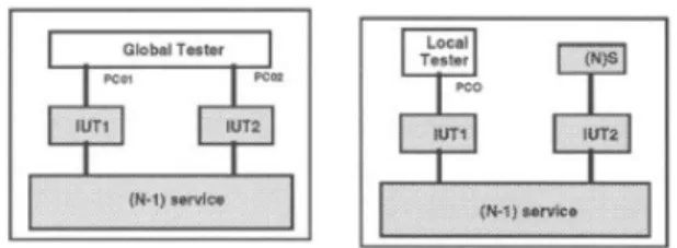
Layered design of communication protocol commonly uses a 3-layer pattern where two protocol entities rely on one pre-exisiting communication service to render in turn a
value-Fig. 1. Global Testing Architecture (left) and Local Testing Architecture (right)
<<Actor>> Client
ClientServerSystem
ProcessRequest <<Actor>>Server
<<Actor>> Network
Fig. 2. Use-Case Diagram for the Client/Server Protocol
added service. Similarly, the interoperatibility testing architec-ture defines a 3-layer architecarchitec-ture where the tester is located on top of one or several protocol entities (IUT1 and IUT2). The Implementation Under Test UTA1 and UT2 are themselves being on top of one pre-existing communication service. Assuming the networked system is made up of two protocol entities, Figure 1 (left part) defines a global testing architecture where the global tester is connected to both protocol entities. Figure 1 (right part) depicts a local testing architecture where the tester is connected to one protocol entity (IUT1).
B. Client/Server Protocol
This section abstractly defines a client/server protocol where the server may acknowledge or refuse the requests issued by the client.
The use-case diagram in Figure 2 delimits the boundary of the communication system and links it to the client and server applications, as well as to underlying, preexisting network.
Figure 3 depicts a successful completion of an inquiry procedure. The service primitive suffixes abbreviate “request”, “indication”, “response”, and “confirm”. Two Protocol Data Units are used: xREQ and xOK. For space reasons, the paper does not show the sequence diagrams developed for the inconclusive termination of the request. In brief, the sequence diagrams of Figures 3 and 4 are merely modified to replace ”ok” by ”nok” and ”OK” by ”NOK”.
Figure 5 depicts the communication architecture that use the client/server protocol.
In terms of protocol machines, Figure 6 depicts the protocol machine associated with the Requester. Figure 7 depicts the protocol machine associated with the Responder.
Figure 8 depicts the reachability graph generated from the SysML model by TTool. Making the reachability graph a Labeled Transition Systems, which enables reuse of verifi-cation techniques originally developed for LTS, in particular
Fig. 3. Service Scenario (successful request)
Fig. 4. Protocol Scenario (successful request)
block Requester ~ in x_req() ~ out x_cnf_ok() ~ out x_cnf_nok() ~ out XREQ() ~ in XOK() ~ in XNOK() block Responder ~ out x_ind() ~ in x_rsp_ok() ~ in x_rsp_nok() ~ in XREQ() ~ out XOK() ~ out XNOK() block Client ~ out x_req() ~ in x_cnf_ok() ~ in x_cnf_nok() block Server ~ in x_ind() ~ out x_rsp_ok() ~ out x_rsp_nok()
Fig. 5. Communication architecture
minimization with respect to an equivalence relation. The transitions of the reachability graph are labeled by those events the designer wants to focus verification on. These events are typically exchanges of signals between pairs of blocks. As far as communication architecture validation is concerned, the events to be preserved by the minimization process are the service primitives exchanged at the boundary between the protocol entities (Requester and Responder on Figure 5) and their respective users (Client and Server on Figure 5). We selected service primitives as observable events to decorate the reachability graph in Figure 8. The minimization process with respect to observational equivalence outputs the quotient automaton depicted by Figure 9.
From the quotient automaton in Figure 9, we obtained the test sequences depicted by Figure 10. If the system stops in an intermediate state (e.g., a state different from 4 and 8), then
IDLE x_req() XREQ() WAITING XOK() x_cnf_ok() XNOK() x_cnf_nok()
Fig. 6. Protocol Machine for the Requester
IDLE XREQ() x_ind() WAITING x_rsp_ok() x_rsp_nok() XOK() XNOK()
Fig. 7. Protocol Machine for the Responder
Fig. 9. Quotient Automaton Preserving the Service Primitives
Fig. 10. Test Sequences derived from the Quotient Automaton
the test fails. Otherwise, it succeeds.
VI. A CASESTUDY OFCONFORMANCETESTING:AUAV A. Testing Architecture
Conformance testing is the process of verifying the cor-rectness of an artifact in the development cycle of a system against its model. For a black box testing approach one may use a testing architecture where the tester accesses the Implementation Under Test (IUT) via one or several Points of Control and Observations (PCOs). Assuming the design is a layered one, Figure 11 depicts such type of conformance testing architecture with two PCOs that respectively test the interfaces of the IUT with its upper and lower layers. B. Informal Specification of the UAV
The UAV can autonomously take off, fly in a stabilized way, and land at its destination or whenever a critical situation is encountered. It takes pictures at given locations. Only the software related to taking pictures is modeled in this case study: the taking off, flying and landing actions are not
Fig. 11. Conformance Testing Architecture
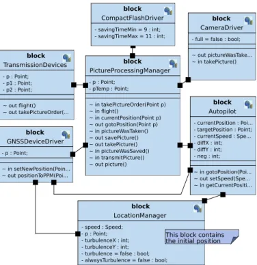
block CameraDriver - full = false : bool; ~ out pictureWasTake... ~ in takePicture() block TransmissionDevices - p : Point; - p1 : Point; - p2 : Point; ~ out flight() ~ out takePictureOrder(... block GNSSDeviceDriver - p : Point; ~ in setNewPosition(Poin... ~ out positionToPPM(Poi... block PictureProcessingManager - p : Point; - pTemp : Point; ~ in takePictureOrder(Point p) ~ in flight() ~ in currentPosition(Point p) ~ out gotoPosition(Point p) ~ in pictureWasTaken() ~ out savePicture() ~ out takePicture() ~ in pictureWasSaved() ~ in transmitPicture() ~ out picture() block Autopilot - currentPosition : Poi... - targetPosition : Point; - currentSpeed : Spe... - diffX : int; - diffY : int; - neg : int; ~ in gotoPosition(Poi... ~ out setSpeed(Spe... ~ in getCurrentPositi... block LocationManager - speed : Speed; - p : Point; - turbulenceX : int; - turbulenceY : int; - turbulence = false : bool; - alwaysTurbulence = false : bool;
block CompactFlashDriver - savingTimeMin = 9 : int; - savingTimeMax = 11 : int;
This block contains the initial position
Fig. 12. Architecture of the UAV
modeled.
Pictures can be taken only when the drone is flying. A remote system located in a ground station can send picture order to the drone. A picture order contains the GPS position of the picture to be taken. To know its current position, a drone has an integrated GPS. When a picture GPS point is reached, with regards to a given threshold, the picture is taken, and then stored on a CompactFlash removable storage system. The system needs 2 seconds to take a picture, and between 4 and 5 seconds to store it in on the memory card. Pictures may be remotely downloaded from the ground station using a download order. Pictures can also be read from the CompactFlash once the drone has come back from its mission. C. UAV Modeling and Test Sequence Generation
Figure 12 depicts the architecture of the UAV in the form of a block instance diagram.
The reachability graph of the UAV depicted by Figure 12 has 674 states and 927 transitions. The reachability graph is labeled to preserve a limited set of signal exchanges: requesting for the flight to start, taking pictures, and saving them. The minimization process outputs the quotient
Fig. 13. Quotient Automaton from the UAV model
automaton depicted by Figure 13. Complying with the approach proposed by the paper, the quotient automaton serves as starting point for generating test sequences.
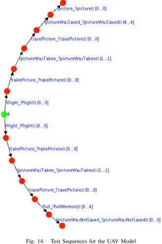
Figure 14 depicts the test sequences generated by TTool: one of them concerns the regular execution of the UAV , the other one evaluates that that the UAV works as expected when the memory for storing pictures is full. These test sequences remain abstract test sequences that need to be transformed into concrete test sequences that may be processed by an actual tester. This transformation is not yet implemented by TTool.
VII. RELATED WORK A. Model-Based Testing for Basic Models
How to derive test sequences from fundamental models such as Extended Finite State Machine or Labeled Transition System has extensively been discussed in the literature, years before the MBSE acronym was coined. In particular, the increasing development of networked systems has stimulated research work on protocol testing In [17]. Most of the models listed in [17] are discrete event Model of Computation. The ad-vent of Cyber Physical Systems has stimulated research work on hybrid models assembling discrete events and continuous paradigms.
B. Model-Based Testing from SysML models
In [10], Gauthier et al use discrete SysML/OCL modeling artifact and add a Modelica support to address continuity. The SysML model is annotated with Modelica and OCL. The approach relies on simulation techniques.
In [12], Lasalle et al. present MBT, a test sequence generation tool developed for SysML in the framework of VETESSS, a project connected with automotive industry. MBT generates functional tests from UML or SysML diagrams edited with the open-source and Eclipse-based tool Topcased. The SysML model of the System Under Test is the input of a tool that generates abstract test suites and transfers them to another tool in charge of creating concrete tests in the form of test scripts. In [22], Ouerdi et al. share an experience in vulnerability test generation from SysML models of smart cards. The authors
Fig. 14. Test Sequences for the UAV Model
use state machine diagrams to model transactions. An Event-Model is derived from the SysML one to generate vulnerability and robustness test cases.
In [19], Gonzales et al. propose a SysML-based modeling methodology for model testing of CPSs, and a SyML-Simulink co-simulation framework.
In [24], Hilken and Peleska combine model-based test gener-ation and requirement tracing. It becomes possible to identify test cases suitable for verifying a given requirement in an automated way.
In [25], Yin et al. propose to derive test cases from activity diagram, not from state machine diagrams (unlike other au-thors). A SysML model edited with Enterprise Architect is transformed into an intermediate representation form that is in turn used to generate test cases automatically.
In [25], Abbors et al. present MATERA, a plug-in of No-Magic’s MagicDraw. MATERA enables requirement modeling in SysML and traces them to the UML model of the System Under Test. MATERA transforms models into input for the Conformiq Qtronic tool, used for automated test generation. The test scripts generated by Qtronic are executed in the NetHawks’s East execution environment. The results of statis-tics analysis of the test run are displayed.
VIII. CONCLUSIONS
Test generation has been acknowledged as one of the most cost-prone activity in the design trajectory of complex systems. The expected benefits of using a model-based approach includes the possibility to reduce that cost by automating a test generation from a model of the system.
The paper proposes a novel approach for generating test sequences expressed in SysML and more precisely in the dialect of SysML supported by the free and open-source tool named TTool. The block instance diagram describing the architecture of the system and the state machine diagrams describing the behaviors of the block instances serve as input to a process that links test generation to formal verification. Indeed, assuming the reachability graph of the SysML model can be computed, TTool generates the latter as a Labeled Transition System whose transitions are labeled by events appropriately selected by the user of TTool. The labeled reachability graph is minimized using Milner’s observational equivalence. The resulting quotient automaton serves as starting point to build up a refusal graph, which serves in turn as starting point for generating test sequences.
Taking a UAV as case study, the paper illustrates the test generation approach in the case of conformance testing. Other types of testing, such as interoperability testing [13] also deserve investigations. Whatever the type of testing, the test sequences must be presented in a standardized form, e.g. using the TTCN notation [18].
REFERENCES
[1] Madni, A., Sievers, M., Model-based systems engineering: Motivation, current status, and research opportunities, Systems Engineering, May 2018.
[2] Object Management Group, https://www.omg.org/.
[3] International Council for Systems Engineering, https://www.incose.org/. [4] Systems Modeling Language, version 1.5,
https://www.omg.org/spec/SysML/, May 2017.
[5] T. Le Sergent, F.-X. Dormoy, A. Le Guennec. Benefits of Model Based System Engineering for Avionics Systems. 8th European Congress on Embedded Real Time Software and Systems (ERTS 2016), Toulouse, France, January 2016,.
[6] F. Mehnni, J.-Y. Choley, N. Nguyen, C. Frazza, Flight Control System Modeling with SysML to Support Validation, Qualification and Certifi-cation, IFAC-PapersOnLine 49-3 (2016), pp. 453–458.
[7] Cameo Systems Modeler, https://www.nomagic.com/products/cameo-systems-modeler.
[8] Rhapsody, https://www.ibm.com/fr-fr/marketplace/architect-for-systems-engineers.
[9] Saqui-Sannes, P. de, Vingerhoeds, R., Apvrille, L, EarlyChecking of SysML Models applied to protocols, 12th International Conference on Modeling, Optimisation and Simulation (Mosim 2018), June 2018, Toulouse, France.
[12] Lasalle, J., Peureux, F., Fondement F., Development of an Automated MBT Toolchain from UML/SysML models, Innovations in Systems and Software Engineering, December 2011, Vol. 7, No. 4, pp 247–256.
[10] Gauthier, J.-M., Bouquet, F., Hammad, A., and Peureux, F. 2015, A SysML Formal Framework to Combine Discrete and Continuous Simu-lation for Testing, 17th International Conference on Formal Engineering Methods. (ICFEM’15), LNCS 9407, p. 134-152.
[11] J.M. Faria, S. Mahomad, N. Silva, Practical Results from the Application of Model Checking and Test Generation from UML/SysML Models of On-Board Space Applications, DASIA 2009 Data Systems in Aerospace, by L. Ouwehan, May 2009.
[13] Saqui-Sannes P. de, Courtiat J-P., Casadessus R., 1995, Verification by abstraction as a preamble for interoperability test suite generation. Protocol Specification, Testing and Verification XIV, Vancouver, BC, Canada.
[14] Brinksma E., Tretmans J. (2001) Testing Transition Systems: An Anno-tated Bibliography. In: Cassez F., Jard C., Rozoy B., Ryan M.D. (eds) Modeling and Verification of Parallel Processes. MOVEP 2000. Lecture Notes in Computer Science, vol 2067. Springer, Berlin, Heidelberg. [15] Hennessy M., Milner R. (1980) On observing nondeterminism and
con-currency. In: de Bakker J., van Leeuwen J. (eds) Automata, Languages and Programming. ICALP 1980. Lecture Notes in Computer Science, vol 85. Springer, Berlin, Heidelberg.
[16] R., Konur S., Yildirim U., Uddin A., Campean F., Gheorghe M., Towards an Integrated Approach to Verification and Model-Based Testing in System Engineering, 2017 IEEE International Conference on Internet of Things (iThings) and IEEE Green Computing and Communications (GreenCom) and IEEE Cyber, Physical and Social Computing (CP-SCom) and IEEE Smart Data (SmartData).
[17] Dssouli, R, Khoumsi, A., Elqortobi M., Bentabar. J., Chapter Three - Testing the Control-Flow, Data-Flow, and Time Aspects of Com-munication Systems: A Survey. Advances in Computers 106: 95-155 (2017). Peleska, J., Huang W., Industrial-Strength Model-Based Testing of Safety-Critical Systems, 2016, International Symposium on Formal Methods, Limassol, Cyprus.
[18] TTCN standard, ESTI n. ES 201 873-1, http://www.ttcn-3.org/ [19] Carlos A. Gonz´alez, Mojtaba Varmazyar, Shiva Nejati, Lionel C. Briand
and Yago Isasi, Enabling Model Testing of Cyber-Physical Systems. In Proceedings of ACM/IEEE 21th International Conference on Model Driven Engineering Languages and Systems (MODELS 2018). ACM, New York, NY,USA, 11 pages.
[20] Drira, K., The refusal Graph: a Tradeoff between Verification and Test, 6th International Workshop on Protocol Test Systems (IWPTS’93), 0. Rafiq (ed.), Pau (France), September 1993, pp.301-316.
[21] Eliyah Kilada, Project Report Class: ECE/CS 5745/6745, “A C++ Implementation of an Efficient Algorithm for Labeled Transition Sys-tem Minimization Based on Bisimulation Equivalence”, Project Re-port Class: ECE/CS 5745/6745, Fall 2008. http://www.ece.utah.edu/ ki-lada/ClassProjects/BisimulationMinimization.pdf
[22] Ouerdi, N., Azizi, M., J.L. Lanet, Azizi, J.L., Ziane, M., EMV Card: Generation of Test Cases based on SysML Models, International Con-ference on Electronic Engineering and Computer Science, 2013, IERI Procedia 4 ( 2013 ) 133 – 138.
[23] Richards, D., Stuart, A., Hause, M., Testing Solutions through SysML / UML, Incose, Singapore, July 2019, Vol. 19, No. 1, pp. 760-774. [24] Hilken C., Peleska J. Model-Based Testing Against Complex SysML
Models. In: Drechsler R., K¨uhne U. (eds) Formal Modeling and Veri-fication of Cyber-Physical Systems. Springer Vieweg, Wiesbaden, June 2015.
[25] Yin, Y., Xu, Y., Chen, Y., An Automated Test Case Generation Ap-proach based on Activity Diagrams of SysML, International Journal on Performability Engineering, Vol. 13, No. 6, October 2017, pp. 922-936. [26] Abbors, F., B¨acklund, A., Truscan, D., MATERA - An Integrated Framework for Model-Based-Testing, Proceedings of the 17th IEEE International Conference and Workshops on Engineering of Computer Based Systems 2010, pp. 321-328.
[27] Peleska, J., Model-based Avionic Systems Testing for the Airbus Family, 23r IEEE European Test Symposium, Amsterdam, The Netherlands, 2018.