HAL Id: hal-01933464
https://hal.archives-ouvertes.fr/hal-01933464v2
Submitted on 7 Jan 2019
HAL is a multi-disciplinary open access
archive for the deposit and dissemination of
sci-entific research documents, whether they are
pub-lished or not. The documents may come from
teaching and research institutions in France or
abroad, or from public or private research centers.
L’archive ouverte pluridisciplinaire HAL, est
destinée au dépôt et à la diffusion de documents
scientifiques de niveau recherche, publiés ou non,
émanant des établissements d’enseignement et de
recherche français ou étrangers, des laboratoires
publics ou privés.
A Tool-Supported Approach for Building the
Architecture and Roadmap in MegaM@Rt2 Project
Andrey Sadovykh, Alessandra Bagnato, Dragos Truscan, Pierluigi Pierini,
Hugo Bruneliere, Abel Gomez, Jordi Cabot, Orlando Avila-García, Wasif Afzal
To cite this version:
Andrey Sadovykh, Alessandra Bagnato, Dragos Truscan, Pierluigi Pierini, Hugo Bruneliere, et al.. A
Tool-Supported Approach for Building the Architecture and Roadmap in MegaM@Rt2 Project. SEDA
2018: Proceedings of 6th International Conference in Software Engineering for Defence Applications,
Jun 2018, Rome, Italy. pp.265-274, �10.1007/978-3-030-14687-0_24�. �hal-01933464v2�
A tool-supported Approach for Building the
Architecture and Roadmap in MegaM@Rt2
project
Andrey Sadovykh1−2, Alessandra Bagnato2, Dragos Truscan3, Pierluigi
Pierini4, Hugo Bruneliere5, Abel G´omez6, Jordi Cabot7, Orlando
Avila-Garc´ıa8, and Wasif Afzal9
1
Innopolis University, 420500 Innopolis, Respublika Tatarstan, Russia [email protected]
2 Softeam, 21 avenue Victor Hugo, 75016 Paris, France
[email protected], [email protected]
3 ˚Abo Akademi University, 20520, Turku, Finland, [email protected] 4
Intecs S.p.A., Via U. Forti 5, 56121 Pisa, Italy, [email protected]
5 IMT Atlantique, LS2N (CNRS) & ARMINES, 44000 Nantes, France,
6
IN3, Universitat Oberta de Catalunya, Spain, [email protected]
7
ICREA, Spain, [email protected]
8
Atos, Subida al Mayorazgo, 24B, 38110 Tenerife, Spain, [email protected]
9 M¨alardalen University, Sweden, [email protected]
Abstract. MegaM@Rt2 is a large European project dedicated to the provisioning of a model-based methodology and supporting tooling for system engineering at a wide scale. It notably targets the continuous development and runtime validation of such complex systems by devel-oping the MegaM@Rt2 framework to address a large set of engineering processes and application domains. This collaborative project involves 27 partners from 6 different countries, 9 industrial case studies as well as over 30 different tools from project partners (and others). In the con-text of the project, we opted for a pragmatic model-driven approach in order to specify the case study requirements, design the high-level architecture of the MegaM@Rt2 framework, perform the gap analysis between the industrial needs and current state-of-the-art, and to plan a first framework development roadmap accordingly. The present paper concentrates on the concrete examples of the tooling approach for build-ing the framework architecture. In particular, we discuss the collabora-tive modeling, requirements definition tooling, approach for components modeling, traceability and document generation. The paper also provides a brief discussion of the practical lessons we have learned from it so far. Keywords: Model-Driven Engineering, Requirement Engineering, Ar-chitecture, UML, SysML, Traceability, Document Generation, Modelio
1
Introduction
MegaM@Rt2 is a three-years project, funded by European Components and Systems for European Leadership Joint Undertaking (ECSEL JU) under the H2020 European program, that started in April 2017 [1]. The main goal is to create an integrated framework incorporating methods and tools for continuous system engineering and runtime V&V [2, 8]. The underlying objective is to develop and apply scalable model-based methods and tools in order to provide improved productivity, quality, and predictability of large and complex industrial systems [9].
One of the main challenges is to cover the needs coming from diverse and heterogeneous industrial domains, going from transportation [3] and telecom-munications to logistics. Among the partners providing use cases in the project, we can cite Thales, Volvo Construction Equipment, Bombardier Transportation and Nokia. These organizations have different product management and engi-neering practices, as well as regulations and legal constraints. This results in a large and complex catalog of requirements to be realized by the architecture building blocks at different levels of abstraction. Thus, the development of the MegaM@Rt2 framework is based on a feature-intensive architecture and a related implementation roadmap.
The MegaM@Rt2 framework plans to integrate more than 30 tools imple-menting the above mentioned methods and satisfying requirements of the case studies. The tools features are grouped in three conceptual tool sets:
1. MegaM@Rt Systems Engineering Tool Set regroups a variety of current en-gineering tools featuring AADL, EAST-ADL, Matlab/Simulink, AUTOSAR, Method B or Modelica, SysML and UML in order to precisely specify both functional and non-functional properties. Moreover, system level V&V and testing practices will also be supported by this tool set.
2. MegaM@Rt Runtime Analysis Tool Set seeks to extensively exploit system data obtained at runtime. Different methods for model-based V&V and model-based testing (MBT) will be rethought and/or extended for runtime analysis. Model-based monitoring will allow to observe executions of a system (in its environment) and to compare it against the executions of correspond-ing model(s). Monitorcorrespond-ing will also allow a particular system to be observed under controlled conditions, in order to better understand its performance. 3. MegaM@Rt Model & Traceability Management Tool Set is a key part of the framework as it is dedicated to support traceability between models across all layers of the system design and execution (runtime). This can go from highly specialized engineering practices to low-level monitoring. Relying on the unification power of models, it should provide efficient means for describ-ing, handling and keeping traceability/mapping between large-scale and/or heterogeneous software and system artifacts.
Building Architectures and Roadmaps in MegaM@Rt2 3
Model-based approaches for specification have been developed consistently during almost two decades [4]. Automated document generation was one of the first benefit offered by the Model-driven Architecture (MDA) [10, 4]. Indeed, models as the first-class entities of the engineering process should contain all the necessary information for the design documentation. However, several challenges arise. First, the architect team should decide the right organization for the global architecture model. Second, it should be carefully planned which level of details is appropriate for the design of the individual contributions. Third, it should be considered that the architecture model will be used during 3 years of the project for numerous purposes, and thus needs to be prepared to accommodate for changes in methodology. Fourth, several documents need to be generated by extracting the relevant information from all over the architecture model.
In this paper, we present our experience on providing and utilizing model-based tool support for defining MegaM@Rt2 framework architecture, to identify the solution to be implemented in the context of the project and to obtain a cor-responding roadmap for the development of architecture components throughout the project.
2
Architecture specification approach
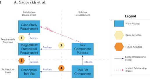
We adopted a practical approach for the architecture specification that is partic-ularly adapted to collaborative projects such as MegaM@Rt2, integrating tools coming from several parties [5, 6]. As modeling language, we took a Systems Modeling Language (SysML) [11] subset for requirements specification and a Unified Modeling Language (UML) [12] subset for the high-level architecture specification. The approach to define the MegaM@Rt2 framework architecture is depicted in Fig. 1. We splitted the architecture model in several parts, dividing the responsibilities among: the Work Package (WP) leaders, the tool providers and the case study providers, as detailed in the following list:
– Requirements/Purposes are specified using SysML
• Case Study Requirements are specified by case study providers,
• Framework Requirements are specified by WP leaders, refining the Case Study Requirements
• Tool Purposes are specified by tool providers with the aim to realise a specific subset of the Framework Requirements
– Architecture is specified in UML
• Conceptual Tool Set is specified by the WP leaders and represents the basic architecture of the MegaM@Rt2 Framework
• Tool Set Component is each tool instance, specified by tool providers, implementing part of the MegaM@Rt2 Framework functionalities • Common Interfaces - specified by tool providers,
• Common deployment frameworks - specified by tool providers
In addition, to support the integration of each Tool Set Component into the MegaM@Rt2 Framework, the following additional elements has been identified:
Fig. 1. Overview of the Architecture and Development process in MegaM@Rt2.
– Common Interfaces, specified by tool providers, to support data and model exchange between tools
– Common Deployment Frameworks, specified by tool providers, to highlight possible issues related to hardware and software platforms
At the Requirements/Purposes level, the needs of industrial partners have been collected and classified by means of Case Study Requirements, from which we specified (Activity 1) the MegaM@Rt2 Framework Requirements. For the latter, we identify (Activity 2) a set of Tool Component Purposes that will realize the case study requirements. At the Architecture level, each Conceptual Tool Set component and and the relevant interfaces are identified (Activity 3) to satisfy framework requirements. Then, for the Conceptual Tool Set we specify (Activity 4) concrete Tool Set Components to realize the desired functionality. Those Tool Set Components expose features (i.e. purposes) that are progressively available, during the project time frame, based on specific development plan. The roadmap is defined as the set of tools components purposes available at each project milestone.
3
Tooling approach
Appropriate tooling support is important for the success of the model-driven engineering process shown in Fig. 1. In order to provide tool support for our architecture specification approach, we selected the Modelio and Constellation tools provided by one of the project participants: the SOFTEAM partner.
When collecting inputs of 50 users, it was important to provide guidelines and diagram templates. Otherwise, the integration work may become extremely challenging. As such, we defined a set of template diagrams both for specifying requirements and for collecting tool purposes. Users were able to clone these templates inside the model to describe their concrete tools.
Building Architectures and Roadmaps in MegaM@Rt2 5
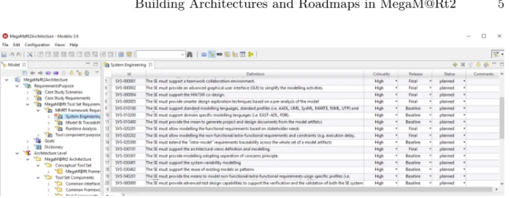
Fig. 2. Requirements editing with Modelio.
In the next subsections we are providing more details on how different fea-tures of the tool were used to support our approach.
3.1 Architecture specification
Modelio is an MDE workbench supporting standard modeling languages such as UML, SysML among others. All the modeling notations can be used in the same global model repository which is important for model traceability and management.
Requirements modeling. In our approach, requirements originated from dif-ferent sources, i.e. from 9 case study providers and 22 tool providers. In order to have an uniform approach for requirement specification that would facilitate gap analysis and roadmap identification, we defined requirement templates that were used to define the expected properties to be collected, such as criticality for the case study requirements and planned release date for tool purposes.
Modelio allowed us to edit requirements in both diagram view and tabu-lar view (see Fig. 2). The requirements were manually edited or automatically imported from other documents, e.g. MS Excel.
Architecture modeling. On the architecture level, we used Class and De-ployment diagrams. We limited modeling to a subset of UML to enforce the common understanding of the architecture and simplify editing. In particular, we choose to use UML Components, Interfaces, Associations, Generalizations and Dependencies.
For tool components, we set a template for the architecture specification that included class diagram to specify functional interfaces, tool components subordinates and the relation to the conceptual tool set in the framework, and deployment diagrams to identify the execution environment of the tool com-ponent. In addition, Package diagrams have been used to define the high level structure of the MegaM@Rt2 framework architecture.
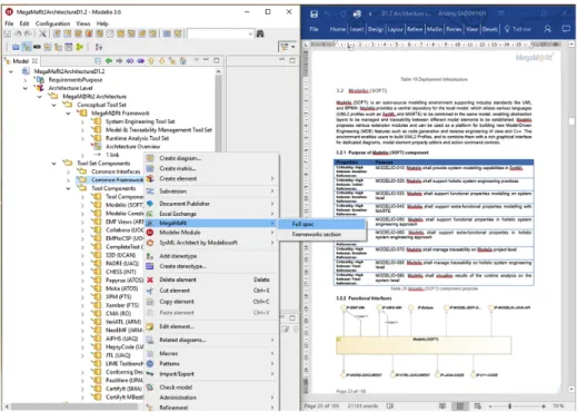
Fig. 3. Editing architecture and documentation with Modelio.
For instance, Fig. 3 shows that the MegaM@Rt2 framework architecture is composed of three parts corresponding to the three WPs of the project: Sys-tem Engineering, Runtime Analysis, and Model and Traceability Management, respectively.
In Modelio, the documentation (Fig. 3) can be added in the textual notes or attached as separate documents. Both plain text and rich text notes are supported. In our work, we deliberately restricted editing to plain text notes to make sure that the generated documents are formatted correctly.
Fig. 4. Example: Traceability links among the tool set, framework and case study requirements.
Building Architectures and Roadmaps in MegaM@Rt2 7
Requirements traceability. Once the requirements have been specified, for each tool component we defined a traceability matrix to link case study require-ments to framework requirerequire-ments, and respectively framework requirerequire-ments to tool purposes as depicted as described by Activities 1 and 2 of the modeling approach in Fig. 1. This allowed us to use instant traceability diagrams, as the one in Fig. 4, to visualise the whole set of dependencies for a given requirement. This proved beneficial not only for the requirement analysis and toolset integra-tion planning, but also for identify common interfaces for tool components and visualise gaps for the requirements analysis.
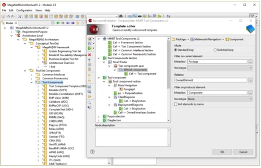
Generating documents. Modelio offers fairly flexible model query and docu-ment generation facilities that were used for editing and maintaining four spec-ifications in the project. The template editor (Fig. 5) was particularly useful to implement custom extraction of model elements in order to create specific sections of the document.
In the example below, the template specifies that the generator will search for a Tool Components package, look at all the UML components to generate a tool section. This document section will include introductory paragraph, Purpose subsection, subsections for all class and deployment diagrams as well as section on the owned interfaces.
When editing the architecture model, it is quite useful to see the generation result. Thus, along with developing custom document templates, we integrated the document generation to the Modelio interface. That way regular users could call the document generation directly from the tool using a context menu (Fig. 6).
3.2 Collaborative model editing
Modelio Constellation [7] is the model sharing, collaborative editing, versioning and configuration management facility that allow hundreds of modellers to work together on the same common and shared model. Indeed, authoring an architec-ture deliverables in MegaM@Rt2 project required contributions of 27 partners. Thus, around 50 users worked together on the single model. On the regular basis, users connected to the Constellation server, synchronised the local model with the central repository, edited the architecture and generated the documents with alway updated templates. The documentation templates and user interfaces for document generation were developed continuously and had to be rolled out to the whole large team of modellers without interrupting the work process. It was important to provide versioning and conflict resolution when editing touched the common artifacts. Last but not least, several different deliverable were generated out of the same model. Therefore, the branching facility allowed to fix the state when the deliverable were released.
Building Architectures and Roadmaps in MegaM@Rt2 9
4
Conclusions
In this paper, we presented the tool support we used in order to identify and spec-ify the architecture of the MegaM@Rt2 framework using model-driven principles and practices. Our approach enforced the coordination and collaboration among many different stakeholders and thus manageability of this complex project. In-deed, the main benefits of our model-driven approach are that all information was collected from different stakeholders and stored using one single model using a single tool.
This model was used as a central repository, that every project partner can access and update using model versioning techniques. In addition, having all the information in one single place, allowed us not only to constantly monitor the status of the process and to trace the requirements of the framework compo-nents, but also to easily generate necessary artefacts (such as documents, tables, diagrams) from the model, whenever needed.
However, using a model-based approach also had some challenges and limi-tations.
The first of such challenge was that different project participants had differ-ent levels of familiarity with modeling tools in general and with Modelio and Constellation in particular. This issue has been addressed by providing several project-wide online webinars along with proper documentation on describing how the tools can be used to support the architecture specification approach. The Modelio support team was helpful in solving the licensing issues, helping with installation and resolving model versioning conflicts.
A second challenge came from the fact that 50 modellers worked collabora-tively with the models which could trigger inconsistencies, conflicts and omis-sions in the collected information. Using the Constellation tool we were able to support model versioning and collaborative modeling. In addition, we splitted the model in several parts corresponding to each work package and we provided clear guidelines on how the work is organized.
A third challenge came from the limitations of the selected tools. For in-stance, there were different restrictions on how the styling of the documents generated from the models could be configured and how the information could be visualized using different types of diagrams. Manual effort is also required to create document templates and configure the document generators. However, once the generators were created they could be reused easily and effectively.
In addition to the above challenges, some industrial partners were already using an existing company-wide tool chain that is not part of our project con-sortium. In this case, they still gave their requirements, which were mapped to MegaM@Rt tool set capabilities. However, in such cases, the industrial partners had an additional validation of the acceptance of their requirements using both the MegaM@Rt tool set capabilities as well as the capabilities of their in-house tool set.
Overall, the experience with Modelio and Constellation was mostly positive and the tool will be further used in other architecture deliverables at later stages of the project and as the reference document.
Acknowledgement. This project has received funding from the Electronic Component Systems for European Leadership Joint Undertaking under grant agreement No. 737494. This Joint Undertaking receives support from the Euro-pean Union’s Horizon 2020 research and innovation program and from Sweden, France, Spain, Italy, Finland and Czech Republic.
References
1. ECSEL JU MegaM@Rt2 Project Website, https://megamart2-ecsel.eu/. (2018). 2. Fitzgerald B., Stol K.J.: ”Continuous Software Engineering: A Roadmap and
Agenda”. Journal of Systems and Software 123, 176–189 (2017).
3. Wallin P., Johnsson S., Axelsson J.: ”Issues Related to Development of E/E Product Line Architectures in Heavy Vehicles”. In: 42nd Hawaii International Conference on System Sciences (HICSS 09). Big Island, HI, USA. IEEE (2009).
4. Di Ruscio D., Paige R.F., Pierantonio A.: ”Guest Editorial to the Special Issue on Success Stories in Model Driven Engineering”. Journal Science of Computer Programming. 89(PB), 69–70 (Sep 2014), http://dx.doi.org/10.1016/j.scico.2013. 12.006.
5. Afzal W., Bruneliere H., Di Ruscio D., Sadovykh A., Mazzini S., Cariou E., Truscan D., Cabot J., Field D., Pomante L., Smrz P.: ”The MegaM@Rt2 ECSEL Project: MegaModelling at Runtime - Scalable Model-Based Framework for Continuous De-velopment and Runtime Validation of Complex Systems”. In: 20th EUROMICRO Conference on Digital System Design (DSD). IEEE, 2017.
6. Bruneliere H., Mazzini S., Sadovykh A.: ”The MegaM@Rt2 Approach and Tool Set”. In: DeCPS Workshop, 22nd International Conference on Reliable Software Technologies. Ada-Europe, 2017.
7. Desfray P.: ”Model repositories at the enterprises and systems scale: the modelio constellation solution”. In: 1st International Conference on Information Systems Security and Privacy (ICISSP). IEEE, 2015.
8. ISO/IEC/IEEE: ”ISO/IEC/IEEE 29148: Systems and software engineering – Life cycle processes – Requirements engineering”. (Nov. 2011).
9. ISO/IEC: ”ISO/IEC 25010: Systems and software engineering – Systems and soft-ware Quality Requirements and Evaluation (SquaRE) – System and softsoft-ware quality models”.(Mar. 2011).
10. OMG: Model Driven Architecture (MDA) Guide rev. 2.0, http://www.omg.org/ cgi-bin/doc?ormsc/14-06-01.
11. OMG: OMG Systems Modeling Language (OMG SysML), Ver. 1.4, http://www. omg.org/spec/SysML/1.4/.
12. OMG: Unified Modeling Language (UML), Ver. 2.5, http://www.omg.org/spec/ UML/2.5/.