Science Arts & Métiers (SAM)
is an open access repository that collects the work of Arts et Métiers Institute of Technology researchers and makes it freely available over the web where possible.
This is an author-deposited version published in: https://sam.ensam.eu Handle ID: .http://hdl.handle.net/10985/7398
To cite this version :
Laurent BLERON, Louis DENAUD, Robert COLLET, Rémy MARCHAL - Experimental study of locally loaded timber in compression perpendicular to the grain - European Journal of
Environmental and Civil Engineering - Vol. 15, n°3, p.357-366 - 2011
Any correspondence concerning this service should be sent to the repository Administrator : archiveouverte@ensam.eu
Experimental study of locally loaded timber
in compression perpendicular to the grain
Laurent Bleron
*- Louis Denaud* - Robert Collet
*-
Rémy
Marchal
** Laboratoire Bourguignon des Matériaux et Procédé (LaBoMap), EA3633 Arts et Métiers ParisTech Cluny
Rue Porte de Paris F-71250 Cluny
louis.denaud@ensam.eu
ABSTRACT. Since the test method for compression strength perpendicular to the grain was changed from a partial area to a full area loading test, strength values for softwood in EN 338 were significantly reduced. Consequently, a change in Eurocode 5 was necessary to ensure an equivalent resistance level in compression perpendicular to the grain. Experimental results are presented with wood in compression perpendicular to the grain.A numerical model is also presented. This model was used to establish a rule of calculation proposed at the P21A-Committee of the technical and construction equipment standardization office (BNTEC).
RÉSUMÉ. Depuis que la méthode de caractérisation de la résistance en compression transversale du bois a été modifiée, les valeurs de résistances des bois résineux ont été considérablement réduite dans la norme EN338. Par conséquent, une modification de l’Eurocode 5 était nécessaire pour assurer un niveau équivalent de résistance. Les résultats expérimentaux d’essais en compression perpendiculaire aux fibres sont présentés. Un modèle numérique est également présenté. Ce modèle a permis d’établir une règle de calcul qui a été proposé au niveau de la commission P21A du Bureau de Normalisation des Techniques et des Équipements de la Construction (BNTEC).
KEYWORDS: compression perpendicular, timber, eurocode 5
1. Introduction
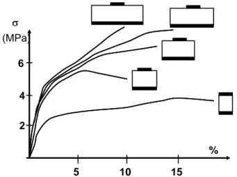
Wood materials in timber applications are subjected to various loading conditions ranging from static to impact forces. Wood under static and quasi-static loading is used in many structural members such as building members, bridges, etc. The European standard EN 338 (EN338, 2003) provides a strength class system for structural timber and strength profiles (characteristic strength values for bending, tension, compression and shear stresses) for each strength class. Contact joints in timber structures are often loaded in compression perpendicular to the grain. Contrary to most types of timber connections (Ehlbeck and al., 1989), (Smith and al., 1988), (Bleron, 2000), the load-deformation behaviour of contact joints is generally very ductile (figure 1). For compression perpendicular to the grain the two options of tests are discussed.
The first one is a test where a block of wood is loaded in uniform compression over the full surface. The second one is a situation where the test specimen is loaded over part of the length corresponding to a rail on a sleeper. The latter method that is used in US and Australia gives higher strength values than the block test because the fibres adjacent to the loaded area contributes in taking the load (figure 1). The first method was chosen in Europe and it was assumed that the rail test results could be derived from the block results. Since the test method for compression strength perpendicular to the grain was changed from a partial area to a full area loading test, strength values for softwood in EN 338 were significantly reduced. Consequently, a change in design rules was necessary to ensure an equivalent resistance level in compression perpendicular to the grain.
Figure 1. Compressive strength perpendicular to the grain 2 4 5 10 15 % 6 σ (MPa)
Compression perpendicular to the grain 3
EN 408 (EN408, 2004) provides an explicit definition of the compressive strength. It is the stress obtained at the intersection with a 0,01h0 off-set line parallel
to the linear part of the stress-strain curve, where h is the height of the specimen (figure 2). Eurocode 5 (Eurocode 5, 2004) enables an increase of design strength values depending on the deformation, the specimen type and loading conditions.
Figure 2. Definition of the maximum compressive load perpendicular to the grain in
accordance with EN 408
The compressive strength of a fully supported beam is:
75
.
1
1
,90 90 , 90 ,×
≤
≤
=
c c c sk
f
and
k
f
[1] Where:- fs is the compressive strength in the contact (area perpendicular to the grain),
- fc,90 is the reference compressive strength according to EN408,
- kc,90 is a factor taking into account the load configuration, the contact length
and the member depth,
- h0 is the gauge length, in millimetres.
A comprehensive survey of research work is given by Gehri (Gehri, 1997), Blass (Blass and al., 2004) and Augustin (Augustin and al, 2006). Eurocode 5 is based on a model set out in (Blass and al., 2004). The starting point for this model is the tests reported in Madsen (Madsen, 2000) where an effective length of contact was found. This length is equal to the length of actual contact increased by 30 mm. The length of 30 mm is also punitive for timber construction, specifically for glulam structures. F c,90,max 0.1 ×F Load Displacement 0.01 × h 0 h h0 c,90,max c,90,max 0.4 ×F
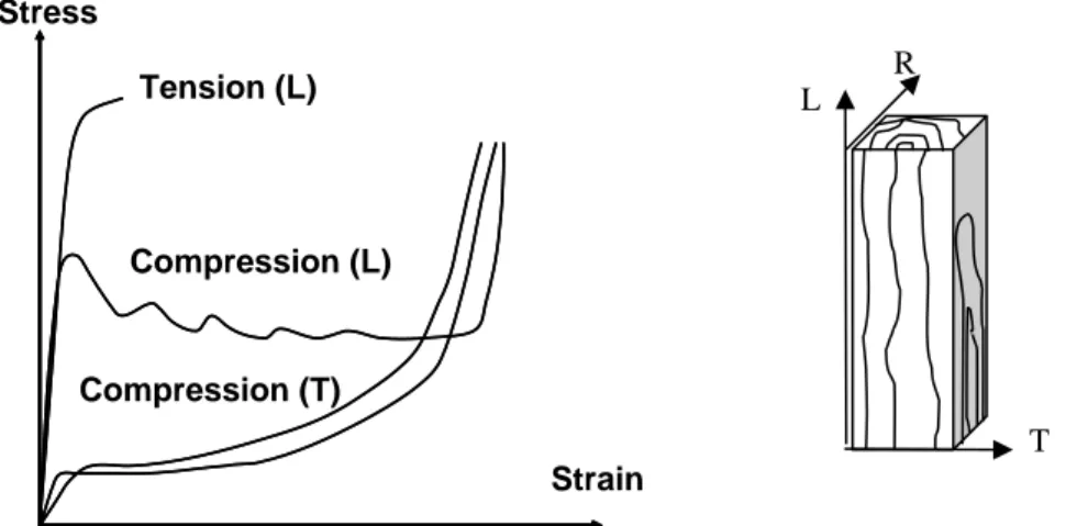
Some empirical models proposed by Riberholt (Riberholt, 2000). Van der Put (Van der Put, 2006) presented an analytical model based on plasticity theory. Wood materials are commonly assumed to be orthotropic for analytical study. The linear material behavior of wood is generally observed in longitudinal and transverse tension, while the stress-strain relationships in compression and shear exhibit significant nonlinearity and ductility (figure 3). When loaded in compression, the response for the three main directions (L: longitudinal, R: radial, T: tangential) can be characterized by an initial elastic region, followed by a plateau region and finally a region of rapidly increasing stress. To simulate wood nonlinearity in shear and compression, Patton-Mallory (Patton-Mallory, 1997) used bilinear functions for wood nonlinear modelling.
Figure 3. Typical stress-strain curves for wood loaded in compression and tension
(Kollmann, 1984)
Here we propose to test different loading cases and simulations in order to check the compression strength perpendicular to the grain of locally loaded timber. The objective is to propose an original formula for estimating the effective contact area in the case of compression perpendicular to the grain depending on the type of loading
2. Material and methods
2.1. Experimental procedure
Mechanical testing was carried out using an INSTRON universal testing machine, with a 100 kN load cell. The standard test method of EN 408 was applied for all tests, resulting in a well defined value for the reference compressive strength
Stress Strain Tension (L) Compression (L) Compression (T) L R T
Compression perpendicular to the grain 5
and other data. The loading rate was 5 mm/min. The compressive strength fc,90
perpendicular to the grain is defined as the conventional value determined by a residual deformation of 0.01h0, where h is the height of the sample. The stiffness of
wood, in the direction perpendicular to the grain, is determined by its modulus of elasticity Ec,90. This secant modulus is conventionally defined as the slope of the
linear part in the stress–strain relationship, between 10% and 40% of the conventional failure stress.
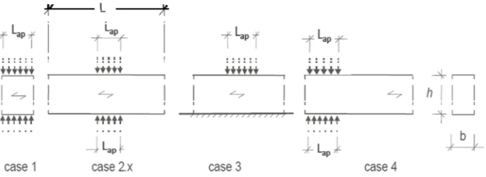
Glued laminated timber blocks of Norway Spruce (Picea abies Karst) were tested to show the compressive strength perpendicular to the grain for different loading condition. Test material was conditioned between 10% and 12% MC. The reference compressive test pieces are summarized in the table 1 and figure 4. The different rules of calculation take into consideration only the effect of the beam heights. The strength in compression perpendicular to the grain being independent of the width, we then chose as a single 78 mm width.
Figure 4. Different loading cases in compression perpendicular to the grain
(Lap=100mm)
Loading cases No of tests
b h L Case 1 Uniform compression – EN 408 22 78 300 100 Case 2.1 Continuous beam in local compression 10 78 300 800 Case 2.2 Continuous beam in local compression 10 78 150 800 Case 2.3 Continuous beam in local compression 10 78 300 160
Case 3 ASTM D 143 10 78 300 800
Case 4 Beam end in local compression 10 78 300 800 Table 1. Dimension of the sample
3. Results
Failure occurs at the plastic threshold by compression and lateral deformation. After local compression failure a load increase is possible. The test results are presented in table 4 (mean & standard deviation). The compression stress perpendicular to the grain is calculated using an effective contact length parallel to the grain. Comparison shows that the member height has no influence on the load-carrying-capacity (comparing case 2.1 and 2.2) for low beams heights. If the timber member protrudes over the end of the contact area, the actual contact length has to be extended on both sides by a length. Indeed, the strength in compression perpendicular to the grain doubles between the case 1 and the case 2.1. Some simulations have been made in order to determine this effective length.
The presented material model has been implemented in the 3D nonlinear explicit finite element simulation code ANSYS. FE analyses were carried out using 8-nodes solid elements (SOLID45). Parameters EL, ER and ET are the moduli of elasticity in the three orthotropic directions and GLR, GLT and GRT are the shear moduli in the respective orthotropic planes. Mechanical behaviour was taken as orthotropic and elastoplastic. Data of spruce used for the model were taken from literature ((Guitard, 1987), (Pluvinage, 1992)) (table 2 and table 3). The mechanical properties values were chosen based on our test samples densities and elastic modulus to better estimate the behaviour of wood.
Young’s Modulus (MPa) EL = 10700 ER = 710 ET = 430 Shear Modulus (MPa) GLR = 500 GRT = 23 GLT = 620 Poisson’s ratio NuLR = 0.40 NuRT = 0.51 NuLT = 0.57
Table2. Elastic properties of spruce
Direction L Direction R Direction T
Tensile yield (MPa) 26.5 3 3
Tensile tangent (MPa) 10000 1 1
Compression yield (MPa) 26.5 3 3
Compression tangent (MPa) 10000 1 1
Shear yield (MPa) 3.85 2.2 7
Shear tangent (MPa) 1 1 1
Table 3. Plastic properties of spruce
Before predicting the plastic strain for different loading cases, the finite element model used has to be calibrated. The model has been validated by comparing numerical simulations to experimental tests which have been performed (table 4). The digital model being in agreement with the experimental tests, multiple
Compression perpendicular to the grain 7
configurations have been simulated with different beams sizes, lengths of supports and load configurations. Then different loading cases have been simulated to characterize the influence of the height of the beam, the length of the support and the adjacent part on beam which is not loaded.
Density (kg.m-3) E90,mean (MPa)
Experimental fc,90,mean (MPa) Experimental fc,90,mean (MPa) FE Model Case 1 440 (27.1) 190 (13.7) 3.01 (0.35) 3.06 Case 2.1 439 (29.8) 514 (32.7) 6.37 (0.98) 6.59 Case 2.2 450 (29.4) 325 (49.8) 6.14 (0.92) 6.41 Case 2.3 466 (33.6) 326 (32.5) 5.05 (0.78) 4.90 Case 3 464 (25.5) 682 (77.1) 7.79 (1.13) 6.79 Case 4 466 (33.6) 326 (43.8) 5.31 (0.84) 4.94 Table 4. Results
4. Discussion and conclusion
To determine the length beyond support (a) that allows reaching the maximum value for la, we used different values for a beam with a cross section of 300 mm (h)
x 160 mm (b) (figure 5). The loading configuration was an axial compression on discrete supports. Load was created by imposition of a displacement on the surface of the discrete support. Length of support can be raised by addition of a value (la),
mainly dependent of beam height, and in a limited extent of beam width, when support length reaches a certain level which is quite low (figure 6). Fixing the limit of 3% of strength loss, we can note that a ≥ 2.25 la is sufficient to take the maximal value of la.
Figure 5. Model configuration
FEM analyses shows that the plasticized zone of the support is a function of the length of this support and the height of the sample. However, beyond a certain distance, the value remains constant because the end distances do not influence the compressive strength. This conclusion was leading for the size of the test specimens.
Figure 6. Maximal additional contact length on each side (la)
To highlight the threshold length of la, which reached its maximum depending
on actual support length Lap, we are based on the calculation of the embedding strength developed for dowel assemblies. Aeff represents effective contact area that is the width of the sample by the length (Lap + 2×la) in the case of figure 5. Areal represents contact area that is the width b of the sample by the support length Lap. We can define the following equality [2]:
real eff c h
A
A
f
f
=
90 , 90 , [2]where fh,90 is the embedding strength perpendicular to the grain.
In that case, we arrive at a minimum ratio of 4 for softwood strength between C14 and C50. In conclusion, we limit the resistance in compression perpendicular to the grain to 4 times fc,90,k to avoid the wood puncture by small surfaces of contact. To meet this requirement, we have integrated the maximum value of the kc,90 defined by Blass (Blass and al., 2004) to define the threshold length of la. Then, the length la
Compression perpendicular to the grain 9
Finally, according the Eurocode 5, the compressive strength perpendicular to grain for a beam of thickness b has to check the following equation:
90 , mod , 90 , c m k c eff k k f A F ≤ × × =
γ
σ
[3]The efficient support area Aeff should be calculated taking into account the effective contact length corresponding to the length of actual contact Lap, increased from each side by la, according the formula [4] :
⎪ ⎪ ⎪ ⎩ ⎪⎪ ⎪ ⎨ ⎧ + = 6 . 1 25 . 2 20 2 min ap a L a h b l [4]
Consider a cantilever beam of 25 m range with a cantilever joint to 4.4 m from the central support beam with a central support reaction of 47525 daN (figure 7). The length of the central support (lef) according to Eurocode 5 is 157 cm if we used a GL28h glulam beam with a thickness of 135 mm and kmod equal to 0,9 according to the formula [5].
(
)
1
.
25
9
.
0
3
60
135
475250
,90, mod .×
=
×
≤
+
×
=
M k c ef compk
f
l
γ
σ
[5]If we consider now the effective length of support according to the formula [4], the necessary support length is then 65 cm. It is possible to draw the conclusion that the Eurocode 5 overestimates the length of support.
12. Bibliography
ASTM D143, Standard Test Methods for Small Clear Specimens of Timber, Vol 4.10
Augustin M., Schickhofer G., “Behavior of glulam in compression perpendicular to grain in different strength grades and load configurations”, Proceedings of CIB-W18, paper 39-12-6, 2006, Florence, Italy.
Blass, H.J., Görlacher R., “Compression perpendicular to the grain », World Congress of Timber Engineering, 2004, Finland.
Bléron, L., 2000. Contribution à l’optimisation des performances d’assemblages bois en structure ; Analyse de la portance dans les assemblages de type tige ; Université Henri Poincaré, thèse de doctorat, 208 p.
Ehlbeck, J., Görlacher, R., Werner, H. ,”Determination of perpendicular-to-the-grain tensile stresses in joints with dowel-type–fasteners”, Proceedings of CIB-W18, Paper 22-7-2, 1989, Berlin, Germany.
EN 338, Bois de structure - Classes de résistance, 2003, 11 p.
EN 408, Bois de structure et bois lamellé collé. Détermination de certaines propriétés physiques et mécaniques, 2004, 29 p.
CEN, EN 1995-1-1 (Eurocode 5), Design of timber structures. Part 1-1: General. Common rules and rules for buildings, 2004.
Gehri E., “ Timber in compression perpendicular to the grain”, IUFRO 5.02 Timber Engineering, 1997, Copenhagen
Guitard D., Mécanique du matériau bois et composites, Cepadues-Editions, 1987, I.S.B.N. 2.85428.152.7.
Kollmann F., « Principles of wood science and technology », vol. I, Springer Verlag, 1984, Berlin.
Madsen B., Leijten A.J.M., Gehri E., Mischler A. and Jorissen, A.” Behaviour of Timber Connections. Timber, Behavior of Timber Connections”, ISBN 1-55056-738-1, Timber Engineering Ltd, 2000, p 139-162
Patton-Mallory M., Cramer S.M., Smith F.W., Pellicane,P.J., “ Nonlinear material models for analysis of bolted wood connections », J. of Struct. Eng., ASCE 1997. 123(8):1063-70. Pluvinage G., La rupture du bois et de ses composites, Cepadues-Editions , 1992, I.S.B.N. 2.85428.292.2.
Ribberholt H., « Compression perpendicular to the grain of wood », COWI-report P-42239-1,2000.
Smith, I., Whale, L.R.J., Anderson, C., Hilson, B.O., Rodd, P.D.,” Design properties of laterally loaded nailed and bolted joints”, Canadian Journal of Engineering, Vol. 15, n° 4, 1988, pp 633-643.
Van der Put, “Derivation of the bearing strength perpendicular to the grain of locally loaded timbre blocks”, Publication of Delft Wood Science Foundation, T.A.C.M., 2006.


