HAL Id: hal-02299479
https://hal.archives-ouvertes.fr/hal-02299479
Submitted on 27 Sep 2019
HAL is a multi-disciplinary open access
archive for the deposit and dissemination of
sci-entific research documents, whether they are
pub-lished or not. The documents may come from
teaching and research institutions in France or
abroad, or from public or private research centers.
L’archive ouverte pluridisciplinaire HAL, est
destinée au dépôt et à la diffusion de documents
scientifiques de niveau recherche, publiés ou non,
émanant des établissements d’enseignement et de
recherche français ou étrangers, des laboratoires
publics ou privés.
Detection of bearing faults in asynchronous motors
using Luenberger speed observer
Baptiste Trajin, Jérémi Regnier, Jean Faucher
To cite this version:
Baptiste Trajin, Jérémi Regnier, Jean Faucher. Detection of bearing faults in asynchronous motors
us-ing Luenberger speed observer. 34th Annual Conference of IEEE Industrial Electronics (IECON 2008),
Nov 2008, Orlando, United States. pp.3073-3078, �10.1109/IECON.2008.4758451�. �hal-02299479�
OATAO is an open access repository that collects the work of Toulouse
researchers and makes it freely available over the web where possible
Any correspondence concerning this service should be sent
to the repository administrator:
[email protected]
To cite this version:
Trajin, Baptiste and Régnier, Jérémi and Faucher, Jean Detection of
bearing faults in asynchronous motors using Luenberger speed observer.
(2008) In: 34th Annual Conference of IEEE Industrial Electronics (IECON
2008), 10-13 November 2008 (Orlando, United States)
This is an author’s version published in: http://oatao.univ-toulouse.fr/21675
Detection of Bearing Faults in Asynchronous
Motors using Luenberger Speed Observer
Baptiste Trajin, IEEE Student Member
Universit´e de Toulouse; LAPLACE; CNRS, INPT, UPS;
2 rue Charles Camichel BP7122 31071 Toulouse Cedex 07, France Email: [email protected]
Jeremi Regnier, IEEE Member
Universit´e de Toulouse; LAPLACE; CNRS, INPT, UPS;
2 rue Charles Camichel BP7122 31071 Toulouse Cedex 07, France Email: [email protected]
Jean Faucher, IEEE Member
Universit´e de Toulouse; LAPLACE; CNRS, INPT, UPS; 2 rue Charles Camichel BP7122 31071 Toulouse Cedex 07, France Email: [email protected]
Abstract— This paper deals with the application of Luenberger
speed observer for the detection of damaged rolling bearings in asynchronous machines. Vibration monitoring of mechanical characteristic frequencies related to the bearings is widely used to detect faulty operations. However, vibration measurement is expensive and can not always be performed. An alternative is to base the monitoring on the available electrical quantities e.g. the machine stator current which is often already measured for control and protection purposes. This work investigates another detection approach using estimated variables such as mechanical rotating speed. Considering that bearing faults induce load torque oscillations, a theoretical stator current model in case of load torque oscillations demonstrates the presence of phase modulations. Then, a theoretical estimated rotor flux and speed model in case of load torque oscillations demonstrates the presence of harmonics related to load torque oscillations. These components appear in the estimated speed spectrum and can be used for detection purposes. Measurements show that speed spectral energy is modified in specific frequency ranges corresponding to bearing faults. A fault detector is then proposed. The efficiency of the indicator is studied on long data records of measurements for different operating conditions. The investigated indicator proves that the detection of bearing faults is ensured by using estimated mechanical speed.
I. INTRODUCTION
Electrical drives using induction motors are widely used in industrial applications because of their low cost and high robustness. However, faulty operations could be induced by bearing faults [1, 2]. To improve the availability and reliability of the drive, a condition monitoring could be implemented to favor the predictive maintenance. Traditionally, motor condi-tion is supervised using vibracondi-tion analysis, but measuring such mechanical quantities to detect bearing faults is often expen-sive. To overcome this problem, available electrical quantities such as stator current could be used. A general review of monitoring and fault diagnosis schemes using stator current can be found in [3]. Concerning bearing fault detection, several studies demonstrate that specific signatures appear on stator current spectrum [4, 5]. Some papers concern the definition of an automatic indicator performing an extraction of relevant information from the current spectrum [6, 7].
Moreover, closed-loop Luenberger observers are used in several applications for sensorless control [8, 9]. Nevertheless, few papers deal with the application of speed observer for
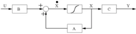
Fig. 1. State-model of the asynchronous drive Σ
bearing fault condition monitoring. The present paper deals with this specific aspect. It has been demonstrated [6, 7, 10] that bearing faults induce load torque oscillations. As a consequence, mechanical speed oscillations due to load torque variations appear and thus can be detected with a speed observer.
In this paper, the detection of speed oscillations is per-formed by using Luenberger observer. Section II recalls the construction of a Luenberger observer for asynchronous drives. Section III proposes a model of estimated variables in case of load torque oscillations such as rotor flux and mechanical rotating speed. The model is based on the assumption that load torque oscillations induce phase modulation on stator currents [11]. This approach is validated with simulated signals and experimental measurements. In section IV, an automatic indicator based on the extraction of spectral energy of the estimated speed is proposed to detect bearing faults. The faulty bearing comes from the after-sales service of a motor manufacturer that declares it as faulty. Then, the fault type is representative of realistic faults. The proposed detector is va-lidated with different mechanical speed operating conditions. Experimental results demonstrate the ability of the proposed detection scheme to distinguish healthy and faulty bearings in several conditions.
II. SPEED OBSERVER FOR ASYNCHRONOUS DRIVES
In order to design a speed observer for the asynchronous machine, a model of the drive has to be defined. A general form of asynchronous machine state model is then recalled in figure 1. The model depends on the allowed input measure-ments and the desired output variables. The matrix B is the input matrix, C the output matrix, A the dynamic matrix, U the input vector, X the state vector and Y the output vector.
A. Asynchronous drive model
Stator currents are often already measured for control purposes. Moreover, in case of bearing fault detection, sta-tor current analysis [6, 7] demonstrates the ability of these quantities to ensure the detection of faulty operations. The supply voltage of the machine can be measured or calculated with the knowledge of the duty-cycle applied on the inverter. Consequently, the supply voltages are defined as the input variables. The estimated stator currents are compared to real measurements in the closed-loop observer and can be defined as output and state variables. Finally, to get the mechanical speed, the rotor flux has to be estimated [8]. Then, the rotor flux is defined as a state variable. As the model is a four-order system, each state, input or output variable, has to be considered in a two-phase coordinate system. The Concordia transform (α,β) is used in the model. Then, the classical first harmonic equations lead to the state model defined in (1).
˙ X = a1 0 a2 −a3ω 0 a1 a3ω a2 a4 0 a5 −ω 0 a4 ω a5 | {z } A X + 1 σLS 0 0 1 σLS 0 0 0 0 | {z } B µ VSα VSβ ¶ | {z } U µ ISα ISβ ¶ | {z } Y = µ 1 0 0 0 0 1 0 0 ¶ | {z } C ISα ISβ φrα φrβ | {z } X (1) with: a1= − µ 1 σTS + 1−σ σTr ¶ , a2=σT1−σrMsr, a3= −σM1−σsr, a4=MTsrr , a5= −T1r ω = pΩmech where:
• Ts is the stator electrical time constant, • Tr is the rotor electrical time constant, • Msr is the mutual stator-rotor inductance, • σ is the leakage coefficient,
• LS is the cyclic stator inductance, • p is the number of pole pairs,
• Ωmech is the mechanical rotating speed.
B. Speed observer
The mechanical rotating speed is estimated by the difference (2) between estimated stator electrical pulsation ˆωs (3) and
estimated rotor electrical pulsation ˆωr (4). The notation ˆx
means that the variables are estimated. ˆ
Ωmech=
1
p( ˆωs− ˆωr) (2)
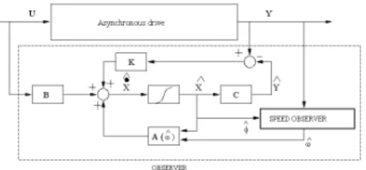
Fig. 2. State-model of the Luenberger observer
ˆ ωs= ˆ φrαˆ˙φrβ− ˆφrβˆ˙φrα ˆ φ2 rα+ ˆφ2rβ (3) ˆ ωr= Msr Tr ˆ φrαISβ− ˆφrβISα ˆ φ2 rα+ ˆφ2rβ (4)
The closed-loop observer is designed according to the model of the asynchronous machine (see figure 1). Moreover, the dynamic of the observer is modified to ensure the convergence of the observer variables, comparing to measurements by using a gain matrix K as depicted in figure 2. The poles of the observer are accelerated and the influence of speed variations is reduced. Variables U and Y are measured variables.
III. ESTIMATED SPEED WITH LOAD TORQUE OSCILLATIONS
It has been demonstrated that load torque oscillations induce mechanical speed oscillations and stator current modulations [12], especially phase modulations (PM) [11]. Then, it has to be shown that the presence of PM on the stator current induces oscillations on the estimated speed.
A. Expression of the mechanical speed
Considering the Luenberger Observer in open-loop condi-tions, the gain matrix K is null. According to the dynamic matrix A, the rotor flux is dependent on the electrical pulsation i.e. the mechanical rotating speed. However, the rotor flux can be expressed only with the stator current and the supply voltage (5). ˆ φrα= R ÷M sr Tr + a1 a3 ¸ ISα+σL1sa3VSα ! dt − 1 a3ISα ˆ φrβ= R÷M sr Tr + a1 a3 ¸ ISβ+σL1sa3VSβ ! dt − 1 a3ISβ (5)
Considering that the inverter imposes a sinusoidal supply voltage (6), where VSαβ is the amplitude of the supply voltage
in (α,β) coordinate system and fsthe supply frequency,
VSα= VSαβcos(2πfst)
VSβ= −VSαβsin(2πfst) (6)
Then, the rotor flux frequency components are similar to the stator current harmonics. As a consequence, without load torque oscillations, the stator current is considered as
sinusoidal. Consequently, the rotor flux is also a sinusoidal wave and the mechanical speed is constant.
In case of load torque oscillations, the stator current is phase modulated at the load torque oscillation frequency fosc (7)
where βI is the current modulation index, ISαβ the amplitude
of stator current in (α,β) coordinate system, φ the phase between stator current and supply voltage and θoscan arbitrary
phase.
ISα= ISαβcos(2πfst + βIsin(2πfosct + θosc) + φ)
ISβ= −ISαβsin(2πfst + βIsin(2πfosct + θosc) + φ)
(7) Using the flux equation (5) for the α component and assuming that θosc = 0, the rotor flux can be generally
expressed as (8). ˆ φrα= A2 ωs sin(2πfst) + A3D(t) + A1 Z D(t)dt (8) where: • A1= ISαβ£Msr Tr + a1 a3 ¤ , • A2=σLVSαβsa3, • A3= −ISαβa 3 , • ωs= 2πfs,
• D(t) = cos(2πfst + βIsin(2πfosct) + φ),
Using the development of phase modulated cosinus in Bessel functions [13], and the assumption that the phase modulated index βI is quite small, the rotor flux expresses
as (9) for ωosc6= ωs. ˆ φrα= Aωs2sin(2πfst) + A3D(t) +A1Jω0s(βI)sin(ωst + φ) +A1J1(βI) · sin((ωs+ωosc)t+φ) ωs+ωosc − sin((ωs−ωosc)t+φ) ωs−ωosc ¸ (9) where:
• J0 is the 0-order Bessel function,
• J1 is the 1-order Bessel function,
• ωosc= 2πfosc.
A similar expression can be established for the β component of the rotor flux (10) for ωosc6= ωs.
ˆ
φrβ=Aω2s cos(2πfst) + A3E(t) +A1Jω0s(βI)cos(ωst + φ)
+A1J1(βI) · cos((ωs+ωosc)t+φ) ωs+ωosc − cos((ωs−ωosc)t+φ) ωs−ωosc ¸ (10) where:
• E(t) = − sin(2πfst + βIsin(2πfosct)).
To simplify the expressions (9) and (10), it can be noticed that J0(βI) ' 1 and J1(βI) ' β2I ' 0 if βI is quite small.
Then, the rotor flux can also be considered as phase modulated at the load torque oscillation frequency (11).
ˆ
φrα= Φrcos(2πfst + βφsin(2πfosct + ψosc) + ψφr)
ˆ
φrβ= −Φrsin(2πfst + βφsin(2πfosct + ψosc) + ψφr)
(11)
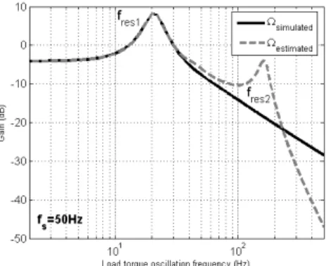
Fig. 3. Gain Bode diagram of simulated transfer functions between simulated, estimated mechanical speed oscillations and load torque oscillations
where:
• βφ is the flux modulation index, • ψosc and ψφr are arbitrary phases.
According to (11) and (3)-(4) and by neglecting square terms, the stator and rotor electrical pulsations are equal to a constant plus an oscillation at the load torque oscillation fre-quency. As a consequence, the estimated mechanical rotating speed is also a constant plus oscillations at multiples of the load torque oscillation frequency, whose amplitudes depend on modulation index βI and βφ (12).
ˆ
Ωmech= Ω0+
X
k
Ωosc(k) sin(2πkfosct) (12)
B. Simulation results
To ensure that load torque oscillations induce specific harmonics on estimated mechanical speed, the asynchronous machine and the observer defined in section II are simulated using Matlab/Simulink. The mean values of simulated and estimated speed are equal, proving the validity of the observer model. Moreover, in case of load torque oscillations, the estimated speed includes harmonics of higher amplitude than the simulated speed. By varying the load torque oscillations frequency, a Bode diagram is established between simulated, estimated speed and load torque oscillations. Figure 3 shows the gain between the speed oscillations and torque oscillations amplitudes. A first resonance frequency appears on the two transfer functions around fres1= 20Hz. A second resonance
frequency appears on the estimated speed around fres2 =
160Hz and is characteristic of the dynamic of the observer. The electromechanical resonance around 20Hz is useful for the detection of bearing faults using stator current spectral analysis [6, 7]. Moreover, the characteristic resonance of the observer can also be used in the detection scheme to favor the detection of high frequency load torque oscillations due to bearing faults.
C. Measurements results with load torque oscillations
After demonstrating the convergence of the observer on simulated results, the estimated speed is compared to speed measurements on a 5.5kW induction machine. A DC machine
Fig. 4. Measured and estimated speed spectrum with load torque oscillations
Fig. 5. Estimated speed spectrum in healthy and faulty conditions
is used as a load. The DC machine is connected to a resistor through a DC/DC converter which controls the DC motor armature current. The reference of current is composed of an oscillating component at the rotating frequency plus an offset in order to induce load torque oscillations around a mean torque value. The supply frequency of the asynchronous machine is set to 50Hz and the mean torque equals 18N.m. Measured and estimated speed spectra are shown in figure 4. It can be pointed out that the first fault harmonics are sensibly equal. Differences between high order harmonics and noise amplitude are of no interest because the aim is to compare the estimated speed in healthy and faulty conditions when speed oscillations appear. Figure 5 shows spectra of the estimated speed of the induction machine in healthy and load torque oscillation conditions. The two noise amplitudes are similar and a comparison between healthy and faulty operations is possible. The amplitude of the speed oscillation component increases due to the load torque oscillation.
IV. BEARING FAULT DETECTION USING SPEED OBSERVER
Many studies demonstrate that bearing faults induce load torque oscillations [6, 7, 10, 14] and thus lead to speed oscillations. Section III emphasized the ability of a Luenberger speed observer to detect speed oscillations. Consequently, the estimated speed can be used to detect bearing faults. In this section, a 6208-type bearing coming from the after-sales service of a motor manufacturer is mounted in the
asynchronous machine. The bearing is declared to be faulty but the fault types or locations are unknown.
As shown in figure 3, the electromechanical system in-cludes a resonance that amplifies the effects of load torque oscillations on mechanical speed and stator currents. As a consequence, the stator current spectral energy detector pre-sented in [6, 7] allows to detect bearing faults preferentially if one of the characteristic bearing fault frequencies [15] equals the resonance frequency. The second resonance frequency, characteristic of the dynamic of the observer, can also be used to detect more efficiently bearing faults on estimated speed. Thus, the detection of bearing faults using speed observer has to be more efficient for several rotating speeds than the detection using stator current monitoring.
A. Bearing characteristic fault frequencies
As a matter of fact, frequencies that could appear in vibration spectrum with appearance of bearings faults are theoretically well known. Harmonics due to defects could appear as combinations of mechanical rotating frequency and characteristic frequencies expressed by (13) [2, 15].
forf = fr 2Nb ³ 1 − Dbcos θ Dp ´ firf = fr 2 Nb ³ 1 +Dbcos θ Dp ´ fc= fr 2 ³ 1 −Dbcos θ Dp ´ (13) where:
• forf outer race fault frequency; • firf inner race fault frequency; • fc cage frequency;
• fr mechanical rotating frequency; • Nb number of balls;
• Db ball diameter; • Dp pitch diameter; • θ contact angle.
The spectral vibration analysis performed on the test bench with faulty bearings shows the appearance of multiples of the characteristic fault frequency related to the inner or outer race. Obviously, combinations of several fault frequencies appear in the vibration spectrum. Strong modulations at fc
and fr can be noticed around the multiples of outer or inner
race fault frequency. Concerning a 6208-type bearing with a rotating frequency of 25Hz, assuming θ = 0, forf= 89.4Hz,
firf = 136Hz and fc= 9.94Hz.
B. Definition of frequency ranges affected by bearing faults
Characteristic fault frequencies depend on the mechanical rotating speed. The speed can be estimated by using the detection of rotor slot harmonics on the stator current spectrum [16]. As the mechanical speed is estimated by the Luenberger observer, a stator current analysis becomes unnecessary. These observations lead us to define an automatic mechanical detec-tor based on estimated speed spectral energy extraction. The estimated speed is computed off-line during 80s. Then, the
(a) fs= 6.7Hz ⇔ firf ' fres1 (b) fs= 13.3Hz ⇔ forf ' fres1 Fig. 6. Cumulative sums of relative error in %
(a) fs= 25Hz (b) fs= 50Hz
Fig. 7. Cumulative sums of relative error in %
fault detector is defined by extracting energies on frequency ranges related to the frequency components at fdef, where
fdef is either the inner or the outer race theoretical fault
frequency. Moreover, the frequency ranges are extended to include modulations linked to the mechanical speed and cage frequencies underlined by a vibration spectral analysis. The chosen frequency ranges are given in (14).
[nfdef− fc; nfdef+ fc]
[nfdef− fr− fc; nfdef− fr+ fc]
[nfdef+ fr− fc; nfdef+ fr+ fc]
(14)
where n ∈ [1; 5].
The proposed indicator uses the relative energy error in the specified frequency ranges between a faulty case and a healthy reference of estimated mechanical speed spectrum. Then, the relative error of energy is estimated in 15 frequency ranges related to the outer race characteristic fault (∆orf) and
15 frequency ranges related to the inner race fault frequency (∆irf). A total relative error is computed by adding relative
errors related to inner and outer race fault frequencies (15).
∆tot(k) = ∆orf(k) + ∆irf(k) with k ∈ [1; 15] (15)
A cumulative sum is then applied on the extracted energy
differences from the frequency ranges related to the investi-gated bearing fault. Finally, the last value of the cumulative sum is defined as the detector value. It is understandable that the detector values have to be close to zero when a healthy case is compared to the healthy reference. In addition, the detector values have to be higher than zero when a faulty case is compared to a healthy reference.
C. Detection of bearing faults using the low frequency reso-nance point
The supply frequency fs is tuned to ensure that one of
the characteristic frequencies is close to the low frequency resonance point. Figures 6(a)-6(b) show the cumulative sums of relative error for two operating points. In figure 6(a), the inner race fault characteristic frequency equals the resonance frequency. The supply frequency fs equals 6.7Hz. In figure
6(b), the outer race fault characteristic frequency equals the resonance frequency. The supply frequency equals 13.3Hz.
The detection of the faulty bearing is ensured for the two operating points especially for fs= 6.7Hz. It can be noticed
that the bad performances of the Luenberger observer at low speed [17] do not affect the detection efficiency. Table I indicates mean and standard deviation of detectors for healthy and faulty operations.
TABLE I
MEAN AND STANDARD DEVIATION OF DETECTORS fs Healthy case detectors Faulty case detectors (Hz) (Mean; Standard deviation) (Mean; Standard deviation)
6.7 (16.8; 55.2) (1020; 116)
13.3 (4.9; 26.7) (454.7; 163.8)
25 (-28.9; 99.1) (378.3; 61.8)
50 (90; 171.7) (1464; 176.7)
D. Detection of bearing faults at nominal and half-nominal speed
Figures 7(a)-7(b) depict the cumulative sums for healthy and faulty operations when the supply frequency equals 25Hz and 50Hz respectively. As the supply frequency equals 50Hz, the inner race characteristic fault frequency is close to the high frequency resonance point on the estimated speed. The detection of the faulty bearing is ensured for the two operating points especially for fs= 50Hz. However the standard
devia-tion increases with the mechanical rotating speed especially in faulty conditions. Table I indicates mean and standard deviation of detectors for healthy and faulty operations. Due to the high frequency resonance point, the efficiency of the detector on the estimated speed is better than the detector efficiency on the stator current [6, 7].
V. CONCLUSION
In this paper, a new method for an automatic detection of bearing faults in induction motors using Luenberger speed observer has been presented. Some mechanical faults induce load torque and mechanical speed oscillations. Thus, the mechanical speed can be used to detect faulty operating condi-tions. As a consequence, a speed observer has been designed to perform speed harmonic detection for bearing fault diagnosis. A simplified approach of the observer demonstrates the ability of the estimated rotating speed to render the speed oscillations. The simulation of the close-loop Luenberger observer shows a different frequency behavior between simulated and observed mechanical speed with regard to the first fault harmonic. The knowledge of the specific resonance frequencies underlined by the Bode diagram is useful to analyse the detection scheme performances.
The detector is tested on real faulty bearings mounted in an asynchronous drive. According to the knowledge of mechanical and geometrical bearing properties, an automatic indicator has been proposed to extract the estimated speed spectral energy in frequency ranges related to bearing faults.
Experimental results show that the detection of bearing faults is ensured using a mechanical speed observer for large mechanical speed ranges.
Moreover, the dynamic of the observer, especially the high frequency resonance, can be used to improve the fault detection. To demonstrate the efficiency and reliability of the detector, and to be more realistic regarding real time implementation of the detector, studies on short data length will be performed in further work.
REFERENCES
[1] B. Raison, G. Rostaing, O. Butscher and C.-S. Maroni, Investigations of algorithms for bearing fault detection in induction drives, IEEE 28th Annual Conference of the Industrial Electronics Society, vol. 2, Nov. 2002, pp. 1696-1701.
[2] J. R. Stack, T. G. Habetler and R. G. Harley, Fault classification and fault signature production for rolling element bearings in electric machines, IEEE Transactions on Industry Applications, vol. 40, no. 3, May-Jun. 2004, pp. 735-739.
[3] S. Nandi and H. A. Toliyat, Condition monitoring and fault diagnosis of electrical machines - a review, IEEE Transactions on Energy Conversion, vol. 20, no. 4, Dec. 2005, pp. 719-729.
[4] J. R. Stack, R. G. Harley and T. G. Habetler, An amplitude modulation de-tector for fault diagnosis in rolling element bearings, IEEE Transactions on Industry Electronics, vol. 51, no. 5, Oct. 2004, pp. 1097-1102. [5] R. R. Obaid, T. G. Habetler and J. R. Stack, Stator current analysis for
bearing damage detection in induction motors, International Symposium on Diagnostics for Electric Machines, Power Electronics and Drives (SDEMPED ’03), Aug. 2003, pp. 182-187.
[6] B. Trajin, J. Regnier, J. Faucher, Bearing Fault Indicator in Induction Machine Using Stator Current Spectral Analysis, Power Electronics Machine and Drives Conference (PEMD ’08), York, Apr. 2008, pp. 592-596.
[7] B. Trajin, J. Regnier, J. Faucher, Indicator for Bearing Fault Detection in Asynchronous Motors using Stator Current Spectral Analysis, IEEE International Symposium on Industrial Electronics (ISIE ’08), Cambridge, Jun-Jul. 2008, pp. 570-575.
[8] M. Cuibus, V. Bostan, S. Ambrosii, C. Ilas and R. Magureanu, Luen-berger, Kalman and Neural Network Observers for Sensorless Induction Motor Control, 3rd International Power Electronics and Motion Control Conference (IPEMC 2000), vol. 3, Aug. 2000, pp. 1256-1261. [9] V. Bostan, M. Cuibus, C. Ilas and R. Magureanu, High Performance
Sensorless Solutions for Induction Motor Control, Power Electronics Specialist Conference (PESC ’03), vol. 2, Jun. 2003, pp. 556-561. [10] M. Blodt, P. Granjon, B. Raison and G. Rostaing, Models for bearing
damage detection in induction motors using stator current monitoring, IEEE International Symposium on Industrial Electronics (ISIE ’04), vol. 1, May 2004, pp. 383-388.
[11] M. Blodt, J. Faucher, B. Dagues and M. Chabert, Mechanical load fault detection in induction motors by stator current time-frequency analysis, IEEE International Conference on Electric Machines and Drives, May 2005, pp. 1881-1888.
[12] R. R. Schoen and T. G. Habetler, Effects of time-varying loads on rotor fault detection in induction machines, IEEE Transactions on Industry Applications, vol. 31, no. 4, Jul-Aug. 1995, pp. 900-906.
[13] M. Abramowitz, I. A. Stegun, Handbook of Mathematical functions with Formulas, Graphs and Mathematical Tables, Dover Publications, New-York, nineth ed., 1964.
[14] H. R. Smith, E. Wiedenbrug and M. Lind, Rotating Element Bearing Diagnostics in a Nuclear Power Plant: Comparing Vibration and Torque Techniques, International Symposium on Diagnostics for Electric Ma-chines, Power Electronics and Drives (SDEMPED ’07), sep. 2007, pp. 17-22.
[15] T. A. Harris, Rolling bearing analysis, Wiley, New-York, 3rd ed., 1991. [16] S. Nandi, S. Ahmed and H. A. Toliyat, Detection of Rotor Slot and Other Eccentricity Related Harmonics in a Three Phase Induction Motor with Different Rotor Cages, IEEE Transactions on Energy Conversion, vol. 16, no. 3, Sep. 2001, pp. 253-260.
[17] R. Zhou and J. S. Lai, Low-Speed Performance Comparison of Induction Motor Sensorless Control Methods, 7th Workshop on Computers in Power Electronics (COMPEL 2000), Jul. 2000, pp. 247-252.