Science Arts & Métiers (SAM)
is an open access repository that collects the work of Arts et Métiers Institute of
Technology researchers and makes it freely available over the web where possible.
This is an author-deposited version published in: https://sam.ensam.eu
Handle ID: .http://hdl.handle.net/10985/15004
To cite this version :
Ali BOUDIS, Ahmed BENZAOUI, H OUALLI, O GUERRI, Annie-Claude BAYEUL-LAINE, Olivier
COUTIER-DELGOSHA - Energy extraction performance improvement of a flapping foil by the use
of combined foil - Journal of Applied Fluid Mechanics p.1651-1663 - 2018
Any correspondence concerning this service should be sent to the repository
Administrator : archiveouverte@ensam.eu
is an open access repository that collects the work of Arts et Métiers ParisTech
researchers and makes it freely available over the web where possible.
This is an author-deposited version published in: https://sam.ensam.eu
Handle ID: .http://hdl.handle.net/10985/15004
To cite this version :
Ali BOUDIS, Ahmed BENZAOUI, H OUALLI, O GUERRI, Annie-Claude BAYEUL-LAINÉ, Olivier
COUTIER-DELGOSHA - Energy extraction performance improvement of a flapping foil by the use
of combined foil - Journal of Applied Fluid Mechanics p.1651-1663 - 2018
Journal of Applied Fluid Mechanics, Vol. 11, No. 6, pp. 1651-1663, 2018.
Available online at www.jafmonline.net, ISSN 1735-3572, EISSN 1735-3645. DOI: 10.18869/acadpub.jafm.73.249.29099
Energy Extraction Performance Improvement of a
Flapping Foil by the Use of Combined Foil
A. Boudis
1,3 †,A. Benzaoui
1, H. Oualli
2, O. Guerri
3, A. C. Bayeul-Lainé
4and
O. Coutier Delgosha
51 Laboratory of Thermodynamics and Energy Systems, Faculty of Physics, University of Science and
Technology Houari Boumediene (USTHB), BP 32 El-Alia, Algiers, Algeria
2 Laboratory of Fluid Mechanics, Ecole Militaire Polytechnique, Bordj El Bahri 16046, Algiers, Algeria 3 Centre de Développement des Energies Renouvelables, CDER, B.P 62 Route de l’Observatoire, 16340
Bouzaréah,Algiers, Algeria
4 Arts et Métiers ParisTech, LMFL, 8 boulevard Louis XIV, 59046 Lille, France
5 Virginia Tech, Kevin T. Crofton, Dept. of Aerospace & Ocean Eng., Blacksburg, 460 Old Turner Street, VA
24061,USA
†Corresponding Author Email: a.boudis@cder.dz (Received April 11, 2018; accepted June 16, 2018)
ABSTRACT
In this study, numerical investigations on the energy extraction performance of a flapping foil device are carried out by using a modified foil shape. The new foil shape is designed by combining the thick leading edge of NACA0012 foil and the thin trailing edge of NACA0006 foil. The numerical simulations are based on the solution of the unsteady and incompressible Navier-Stokes equations that govern the fluid flow around the flapping foil. These equations are resolved in a two-dimensional domain with a dynamic mesh technique using the CFD software ANSYS Fluent 16. A User Define Function (UDF) controls the imposed sinusoidal heaving and pitching motions. First, for a validation study, numerical simulations are performed for a NACA0012 foil undergoing imposed heaving and pitching motions at a low Reynolds number. The obtained results are in good agreement with numerical and experimental data available in the literature. Thereafter, the computations are applied for the new foil shape. The influences of the connecting area location between the leading and trailing segments, the Strouhal number and the effective angle of attack on the energy extraction performance are investigated at low Reynolds number (Re = 10 000). Then, the new foil shape performance was compared to those of both NACA0006 and NACA0012 baseline foils. The results have shown that the proposed foil shape achieves higher performance compared to the baseline NACA foils. Moreover, the energy extraction efficiency was improved by 30.60% compared to NACA0006 and by 17.32% compared to NACA0012. The analysis of the flow field around the flapping foils indicates a change of the vortex structure and the pressure distribution near the trailing edge of the combined foil compared to the baseline foils. Keywords: Flapping foil; Energy extraction; Power coefficient; Combined foil; CFD.
N
OMENCLATUREc foil chord length
CD drag coefficient
CL lift coefficient
CM moment coefficient
COP power coefficient
COPh power coefficient of heaving motion COPθ power coefficient of pitching motion CP pressure coefficient
d maximum vertical displacement of the trailing edge
f flapping frequency
Fy(t) instantaneous vertical force h(t) heaving motion
h0 nondimensional heaving amplitude
‾
mean value over one motion cycle
Mz(t) instantaneous moment P(t) instantaneous total power extracted
Pa total power available in flow
Ph(t) instantaneous power extracted by the
heaving motion
Pθ(t) instantaneous power extracted by the pitching motion
Re Reynolds number (Re = ρcU∞/µ)
St Strouhal number (St = 2ch0f /U∞)
StTE Strouhal number based on the trailing
T flapping period (T = 1/ f )
U∞ free stream velocity
XP chordwise position of pitching axis Xs connecting area location
αeff effective angle of attack
η energy extraction efficiency
θ(t) pitching motion
θ0 nondimensional pitching amplitude
μ dynamic viscosity
ρ fluid density
∅ phase angle between heaving and
pitching motions
χ feathering parameter
ω angular frequency(ω = 2πf)
1. I
NTODUCTIONThe global demand on energy is rapidly increasing as a result of population growth and economic development. Up to date, the worlds energy is mainly generated from fossil fuel sources such as oil, coal and gas. Increasing depletion of fossil resources and the rising concern on GHG emissions have led to increased efforts to find sustainable alternative energy sources such as solar, wind and tidal. In this context, harnessing kinetic energy available in the flows is a very interesting prospect. Traditionally, this type of energy is recovered using conventional turbine with rotating blades (horizontal-axis or vertical-axis turbines). Recently, a bio-inspired flapping foil mechanism has offered an alternative strategy to convert the kinetic energy of wind or tidal into mechanical energy and subsequently into electrical energy. At the beginning, the flapping foil mechanism was used as a thrust generator for micro air vehicles (MAV) or autonomous underwater vehicles (AUV). Afterwards, several studies have found that a flapping foil can switch from a propulsive mode (energy consumption) to a power extraction mode (energy harvesting) if the pitch angle is higher to the induced angle of attack (Jones and Platzer 1997). Flapping foils based energy extraction systems are classified into three types of models according to the actuating mechanism: fully-activated systems, semi-activated systems and self-sustained systems (Xiao and Zhu 2014). In fully-activated systems, the foil undergoes imposed heaving and pitching motions. In semi-activated systems, the pitching motion is semi-activated by energy input, while the recovered energy is ensured through the heaving motion caused by the dynamic lifting forces. The net energy extracted is the difference between the energy consumed to activate the pitching motion and the energy recovered by the induced heaving motion. In self-sustained systems, both pitching and heaving motions are generated by the flow-induced instability and therefore do not require actuation device.
Wu (1972) was the first who investigated the energy extraction from flow using flapping foil. His theoretical results showed that a flapping foil in combined heaving and pitching motion can extract energy from an oscillatory flow. Based on this
concept, McKinney and DeLaurier (1981)
developed the first energy extraction device based on the flapping motion. Their experimental tests in a wind tunnel revealed that the proposed system (called windmill) was competitive compared to other power generation devices. Later, experimental and numerical investigations have been done successively by Davids (1999),Kinsey and Dumas
(2008), Simpson and Triantafyllou (2008), Ashraf et al. (2011) and Lu et al. (2015). All these works confirmed the possibility of using flapping foil to extract energy. In addition, it was observed that the formation and evolution of the leading edge vortex (LEV) play an important role in the energy extraction process. Their results reported that the best efficiency was always achieved when the reduced frequency (f * = fc/U) was in the range 0.10 − 0.15, the phase difference between the pitching and plunging motions ∅ was equal or close to 90◦ and the maximum effective angle of attack αef was
around 30◦. At such conditions, a good
synchronization between the LEV shedding and the heaving motion was observed.
Afterward, numerous attempts have been made to improve the energy extraction performance of a flapping foil. Some researchers focused on using two flapping foils in tandem. This was the case for (Ashraf et al. 2011) that investigated the effects of the phase difference and the distance between the two foils. They found out that in the tandem configuration both averaged power coefficient and efficiency per airfoil were reduced by around 20%compared to a single foil. However, the total efficiency of the optimal tandem configuration increased by 59% compared to a single foil. In a similar study, Kinsey and Dumas (2012) found that optimal tandem configuration has provided high extraction efficiency (up to 64%).
Non-sinusoidal motions were also used to improve the power extraction performance. Ashraf et al. (2011) performed a numerical simulation of the flow over a NACA0014 airfoil undergoing heaving and pitching motions. They found out that compared to the sinusoidal motions, the use of non-sinusoidal flapping motions allowed to improve the power extraction by 17% and the efficiency was improved by 15%. These results were also confirmed by (Xiao et al. 2012), who highlighted the fact that the nature of the pitching motion had a great influence on the power extraction performance of a flapping NACA0012 airfoil. Moreover, according to their results, the trapezoidal pitching motion improved the output power coefficient by 63% and the efficiency by 50%. Later, Lu et al. (2014) showed that an appropriate combination of non-sinusoidal heaving and pitching motions enhanced the energy extraction performance. Their numerical results have shown that the use of a square-like pitching trajectory combined with a toothed-like heaving trajectory, improves the output power coefficient by 87.5% compared to the sinusoidal trajectory.
A. Boudis et al. / JAFM, Vol. 11, No. 6, pp. 1651-1663, 2018.
1653 Through the literature, aerodynamic and biological studies have shown that the performances of a flapping airfoil were also influenced by the foil shape. Some researchers were inspired by the biological flexible structure of the insect wings or fish fins to improve the power extraction performance. Among them, Liu et al. (2013) that carried out numerical simulation to investigate the effect of the flexibility on the power extraction performance of a flapping airfoil. Their results showed that using a flexible leading edge and/or a flexible trailing edge enhanced the power efficiency by 7.68% compared to the rigid wing. Wu et al. (2015) used attached flexible tail at the trailing edge to improve the power extraction of a semi-actuated flapping foil. The tail used was either rigid or passively deformable. They observed that the net power extraction efficiency of the flexible tail was higher than the rigid tail. Then, Xie et al. (2016)
have numerically explored the effects of the gurney flap on the energy extraction performances of flapping airfoil. Their results revealed that, compared to a standard NACA0012 flapping airfoil, the use of optimized gurney flap led to a significant increase of the output power coefficient and the energy extraction efficiency.
Furthermore, modifications of the foil shape were also considered as means to improve the aerodynamic or the hydrodynamic characteristics of the flapping foil. Usoh et al. (2012) investigated the flow over a non-profiled (rectangular) flapping plate to examine the foil shape effect. Their numerical results showed that the use of a non-profiled plate improves the efficiency of power extraction by 5.35% as compared to NACA0012 profile in similar flapping conditions. They also found out that the thickness of rectangular section has a negligible effect on the power extraction performances. Le et al. (2013) carried out two-dimensional Navier-Stokes simulation to explore the morphological effect of bio-inspired scallop-shell. Their results showed that an optimal foil shape with corrugation and camber improved the efficiency by 6% compared to a standard NACA0012 foil. Recently, Wang et al. (2016),
using an in-house UCFD (Unified Computational Fluid Dynamics) software, investigated the influence of the geometrical parameters including the maximum foil thickness, maximum camber, position of maximum thickness and position of maximum camber of a NACA 4 digits and 6 digits series foils on the energy extraction performance of flapping hydrofoil. Their results showed that the performances of the flapping foils increased with the increase of the maximum thickness until an optimum value, and then, decreased with further increase of maximum thickness. For the symmetrical hydrofoils with same maximum thickness, but with different positions, it was observed that the hydrofoil performances increased first, and then decreased when shifting the maximum thickness position from the leading edge to the trailing edge. The best energy extraction performances were obtained at 1/4 chord maximum thickness position. While, for non-symmetric foils with same thickness, the use of larger camber
reduce the energy extraction performances.
Having a step on the foil surface is another technique of geometrical modification that was used to improve the aerodynamic characteristics. The idea of using a stepped airfoil was first introduced by Fogleman and Kline (1972). Thereafter, several experimental and numerical studies were performed to evaluate the performances of this new designed foil. Fertis (1994) investigated through a series of experimental tests on a three-dimensional wing model. His results showed considerable improvement of the aerodynamic characteristics in terms of lift, drag, lift-to-drag ratio and stall angle of attack. Boroomand and Hosseinverdi (2009)
investigated numerically the aerodynamic characteristics of stepped NACA-2412 airfoil. They concluded that, making a step on the lower surface, near the trailing edge, delays the static stall and slightly increases the drag force. However, the lift to drag ratio was improved. More recently, Kamyab et al. (2016) and Kamyab and Ghassemi (2017)
performed a numerical and experimental study of the flow around a stepped NACA0012 airfoil with step on upper surface and both upper and lower surfaces at low Reynolds number. Their results also showed that using step in airfoil leads to a delay in the static stall, an increase in the lift coefficient and a decrease in the Strouhal number that resulted in lower noise generation on the airfoil.
To the authors’ knowledge, no research has been yet carried out to study the aerodynamic characteristics of a stepped flapping foil. Therefore, in this paper, a new stepped foil shape is proposed to improve the energy extraction performance of a flapping foil. The new foil shape considered in this study is composed from two symmetric foils, which are the NACA0012 profile at the leading edge and the NACA006 profile at the trailing edge (Fig. 1). Leading and trailing segments are combined at a well-defined zone along the chord length. The assembly of the two half-profiles creates a step on both top and bottom surfaces. These steps change the vortex activities near the foil surface during the flapping cycle.
The main goal of the present work is to demonstrate the capability of the combined foil shape (or stepped foil) to passively control the vortex activities near the foil surface during the flapping cycle in order to improve the hydrodynamic characteristics. The study was performed using the computational fluid dynamics (CFD) code ANSYS Fluent 16. The solution of governing equations was obtained at low Reynolds number (Re=10 000). The imposed heaving and pitching motions are achieved by using dynamic mesh techniques and User Define Function (UDF).
2. P
ROBLEMD
ESCRIPTIONA
NDN
UMERICALM
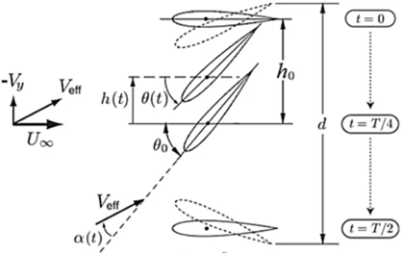
ETHOD2.1 Kinematics of Flapping Foil
The flapping motion is produced by the combination of two periodic motions : heaving h(t) and pitching θ(t). The heaving is a vertical translational motion while the pitching is a rotational motion of the foil around an axis located on the chord line at the distance XP from the leading
edge. Figure 2 illustrates the flapping motions and their kinematic parameters.
Fig. 2. Main kinematic parameters of a flapping foil (Kinsey and Dumas 2014).
In this study, the imposed flapping motion is performed according to sinusoidal trajectories described mathematically by the following equations:
0 ( ) sin h t h c (1) t
0 ( )t sin t (2) Where h0 and θ0 are the maximum amplitudes of heaving and pitching respectively. ω = 2πf is the angular frequency and ∅ is the phase angle between heaving and pitching. c is the chord length.In addition, two dimensionless parameters are used to describe the kinematics of flapping foil, Strouhal number defined by Anderson et al. (1998) as follows : (St = 2fch0/U∞) and Reynolds numbers based on the chord length (Re = ρcU∞/µ). ρ and µ are the fluid density and dynamic viscosity respectively.
The flapping motion in a horizontal flow produces an effective angle of attack αeff and an effective
upstream velocity Veff . These parameters have
significant effects on the hydrodynamic force of flapping foil (Kinsey and Dumas 2008). These are given by the following relations:
arctan 1
( ) eff dh t t t U dt (3)
2
2 eff dh t V t U dt (4) Where U∞ is the freestream velocity and dh(t)/dt is the heaving velocity.Flapping foil can operate in two different modes, propulsion or power extraction, depending on the foil orientation at the effective angle of attack. The operating mode is identified by the dimensionless parameter χ (feathering parameter) defined by
Anderson et al. (1998) as:
0 0/ arctan Uh (5) When the foil is in propulsion mode, then χ < 1 while in power extraction mode χ > 1. For a given flapping frequency the operating mode depends primarily on the maximum amplitude of the pitching.
2.2 Definition of Power Extraction and
Efficiency
The instantaneous power P(t) extracted from the flow by the flapping foil is written as:
( ) h( ) ( )
P t P t P t (6) where Ph(t) is the power extracted by the heaving
motion and Pθ(t) is the power extracted by the pitching motion: ( ) ( ) ( ) h y dh t P t F t dt (7) And ( ) ( ) z( )d t P t M t dt (8)
Fy(t) is the instantaneous vertical force and Mz(t) is
the instantaneous moment.
The instantaneous power coefficient COP is defined
as: 3 ( ) ( ) 0.5 h OP OPh OP P t P t C C C cU (9) This parameter is also written as:
1 ( ) ( ) OP Ldh t M d t C C C c U dt dt (10)
where CL and CM are the lift and the moment
coefficients, respectively.
The mean power extracted
P and the meanpower coefficient
COP over one flapping cycle of period T are calculated as:1 t T ( ) ( ) t T ( ) ( ) y z t t dh t d t P F t M t T dt dt
(11)A. Boudis et al. / JAFM, Vol. 11, No. 6, pp. 1651-1663, 2018. 1655 1 t T ( ) OP t OP C C t dt T
(12) The efficiency of power extraction η is defined as the ratio of the mean extracted power and the power available in the swept fluid area :OP a P c C P d (13) where
Pa1 / 2U d3
is the maximum available power in the flow, d is the maximum vertical displacement of the trailing edge.2.3 Algorithms and Models
A numerical simulation was performed using the commercial CFD code ANSYS-Fluent 16 based on the finite volume method. A segregated pressure solver was used to solve the 2-D unsteady and incompressible Navier-Stokes equations on a moving grid. The pressure-velocity coupling was achieved by means of the SIMPLEC algorithm, and a Green-Gauss Node-Based approach was used for gradient evaluation. The discretization of pressure and momentum terms are based on the second order scheme and the third order MUSCL scheme respectively. For temporal discretization, the first order implicit scheme was used. All simulations are carried out at a Reynolds number, Re = 104.
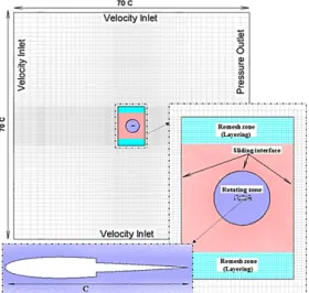
Fig. 3. Mesh and Boundary conditions. Structured cells are built for the meshing of all the computational domain that is divided in three zones: a rotating zone, a layered zone and a fixed zone. The rotating zone is circular and contains the foil. It is meshed with a very fine quadrilateral structured grid in order to capture the physical gradients near the wall accurately. The first grid point in the normal direction of the foil surface is set to 4.610−5c. This first zone ensures the pitching and the heaving of the foil simultaneously or separately. The second zone (translating zone) translates vertically to ensure the heaving motion. In the fixed zone, the mesh is less dense. The connections
between the different zones are managed with non-conformal interfaces.
Dynamic meshes and sliding meshes techniques are applied to ensure the pitching and heaving motions. The dynamic mesh motion was controlled by a User Defined Function (UDF).
2.5 Sensitivity Study and Validation
A sensitivity study is carried out to ensure the independence of the numerical solution on the grid and the time step (∆t).First, the dependence of the spatial resolution on the numerical results was explored. The mesh quality has a noticeable effect on the numerical simulation results. This is more accentuated when the grid is deformable. So, we consider three grids of different densities: Grid-1 is composed of 47 880 cells (with 200 points on the airfoil surface), Grid-2 consists of 87 760 cells (with 400 points on the airfoil surface) and Grid-3 consists of 254 400 cells (with 800 points on the airfoil surface). These simulations are performed at Re = 10000, St = 0.3, h0 = 1, ϕ = 90◦, θ = 73.30◦ and ∆t = T /1000. Figure 4-a represents the instantaneous power coefficient over one flapping cycle computed with the three grids. According to this figure, the difference between the results obtained with Grid-2 and Grid-3 is negligible. Thus, Grid-2 is sufficiently refined to obtain reliable results. Then, it will be applied for all the calculations that follow.
(a)
(b)
Fig. 4. Instantaneous power coefficient over one flapping cycle computed using (a) different grids
Then, an analysis of the temporal resolution is performed to find the appropriate time step size. Figure 4-b displays the variation of the instantaneous power coefficient during one flapping cycle computed with four time steps T/500, T/1000, T/2000 and T/4000. As it is seen in Fig. 4-b the numerical solutions are effectively independent on the time step size if the time step used is equal or higher than T/2000. Therefore, the time-step ∆t = T /2000 is set to all following simulations.
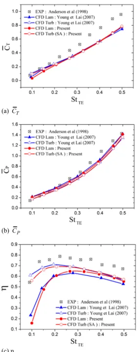
(a) C T
(b) C P
(c) η
Fig. 5. Comparison of (a) mean thrust coefficient, (b) mean power coefficient, and (c) propulsive efficiency versus St at h0 = 0.75 , α0 =
15o, ϕ = 90o and 4104.
In addition to the sensitivity study, a validation study is performed by comparing the computed results to experimental and numerical results published by
Anderson et al. (1998) and Young and Lai (2007).
These numerical simulations are carried out for a 2D incompressible flow over NACA0012 foil undergoing combined heaving and pitching motions at low Reynolds number 4104. The motion parameters are those of the experimental study performed by
Anderson et al.(1998): h0 = 0.75 , α0 = 15◦ and ∅ = 90◦. The flapping frequency has been varied in the range [0.268 − 1.34] to ensure a Strouhal number between 0.1 and 0.5. In this validation study, the Strouhal number is based on the trailing edge excursion, StTE =
2fd/U∞, as in (Anderson et al. 1998). The computed mean thrust coefficient
CT , input power coefficient
CP and (b) the propulsive efficiency (η) arecompared to the experimental results of Anderson et al. (1998) and to those obtained numerically by Young and Lai (2007). Figure 5 shows that the numerical values are slightly lower than the experimental results but with the same tendency. Differences between numerical and experimental results were also found in other CFD studies ( Guglielmini and Blondeaux 2004,
Xiao and Liao 2010 , Karbasian et al. 2015). As reported by Guglielmini and Blondeaux (2004), this difference can be due to the inaccurate procedure used by Anderson et al.(1998) during the experimental measurement of forces and to the 2D approximation used in the numerical simulations. However, a good agreement is obtained between our results and the numerical results published by Young and Lai (2007).
3. R
ESULTSA
NDD
ISCUSSIONSAccording to Kinsey and Dumas (2008),Zhu and Peng (2009), Ashraf et al. (2011) and Xiao et al.(2012), the best energy extraction performances of a flapping foil are obtained when using the following kinematic parameters: St = 0.2 to 0.4, θ0 = 60◦ to 90◦, Xp = 0.25c to 0.5c, h0 = c and ∅ = 90◦. These values give favourable conditions to the formation and shedding process of the leading edge vortex, and also ensure a good synchronization between the lift force and the heaving velocity. Hence, in this study, all simulations are carried out using the following kinematic parameters: h0 = 1c, ∅ = 90◦, Xp = 0.333, αeff ∈ [10◦ − 35◦], St ∈ [0.15 − 0.45] and Re = 10000. All results obtained for the combined foil shape are compared to those of NACA0012 and NACA0006 base foils.
3.1 Effect of the Connecting Area
In this section, the effect of the connecting area location (Xs/c) is investigated. For this purpose, four
locations are considered Xs/c = 0.2,0.33,0.5 and 0.8
respectively. These computations are performed with St = 0.4 and αeff = 30◦.
The variations of COPh,COP,COP and η are displayed in Fig. 6 as a function of Xs/c. Figs. 6-a to
6-c show that the connecting area location has a great effect on the flapping foil performances and that when a combined foil shape is used, the energy extraction performances of the flapping foil are improved. Moreover, Figs. 6-a and 6-b show that
OPh
C has a positive contribution to the power extraction while the contribution from the pitching
A. Boudis et al. / JAFM, Vol. 11, No. 6, pp. 1651-1663, 2018.
1657 (a) Mean power extraction coefficient from
heaving motion
(b) Mean power extraction coefficient from pitching motion
(c) Mean power extraction coefficient
(d) Energy extraction efficiency Fig. 6. Comparison of COPh,COP,COP and η versus Xs/c at St = 0.4 and αeff = 30◦.
motion is negative
COPh0 .
Thus the pitching motion consumes energy. Therefore, the total energy extracted by the flapping foil is dominated by the energy extracted through the heaving motion. It is also found that with the use of an optimal combined foil shape, the energy consumed by the pitching motion is reduced and hereby, the energy extraction performances of the flapping foil are improved. From Figs. 6-c and 6-d, it can be seen that the best performances are obtained when the connecting area is located at the middle of the chord (Xs/c = 0.5). In this case, the power extractionefficiency is improved by 17.32% and 30.60% compared to the NACA0012 and NACA0006 baseline foils respectively (Fig. 6-d). Moving the connection area (Xs/c) toward the leading edge or
the trailing edge considerably decreases the energy extraction performance of the combined flapping foil.
Figure 7 shows the temporal evolution of COPh, COPθ and COP over one flapping cycle for the
combined foil with Xs/c = 0.5 and the baseline foils
at St=0.4 and αeff = 30◦. It is quite clear that the
combined foil shape has a significant effect on the power extraction coefficient. As shown in Fig. 7-a, the instantaneous COPh generated by the combined
foil is higher than that of NACA0012 and NACA0006 baseline foils during the flapping time when t= 0.1T to t= 0.3T and t= 0.6T to t= 0.8T,
while in Fig. 7-b the COPθ is higher when t= 0.4T to 0.5T and t= 0.9T to t= T. As a result, the overall power extraction coefficient (COP) is increased (Fig.
7-c).
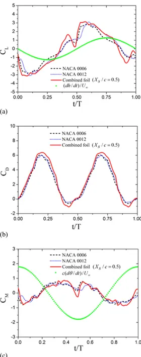
The energy extraction performances of a flapping foil are directly related to the variation of CL and CM
coefficients. As seen in Eq. (10), the power extracted from the heaving motion is determined by the product of the lift coefficient and the heaving velocity. While the power extracted from the pitching motion is determined by the product of the moment coefficient and the angular velocity. The time variation of CL, ((dh/dt)/U∞), CM,((cdθ/dt)/U∞) and CD over a flapping cycle are
drawn in Fig. 8 for the NACA0006 and NACA0012 baseline foils, and the combined foil with Xs/c =
0.5.
Figure 8-a shows that, for the three foil shapes, the lift force and the heaving motion have the same sign during the whole of flapping cycle. This improves the energy extracted from the heaving motion. It is also shown that the instantaneous lift produced by the combined foil is higher than those of the baseline foils. However, the moment coefficient and the angular velocity have opposite signs (Fig. 8-c). Therefore, their effect on the mean power is negative. It is also observed that the moment generated by the combined foil is higher than that
generated by the baseline foils. These results are in agreement with those of DeLaurier and Harris (1974) that the use of a stepped airfoil increases the moment coefficient.
(a) power extraction coefficient from heaving motion
(b) power extraction coefficient from pitching motion
(c) total power extraction coefficient
Fig. 7. Time evolution of (a) COPh , (b) COPθ, and
(c) COP over one flapping cycle at St = 0.4 and
αeff= 30◦.
Figure 8-b presents the temporal variation of the drag coefficients (CD) over one flapping cycle. As it
can be observed that the drag coefficient of the combined foil increases slightly compared to the baseline foils. These results are consistent with those of (Fertis 1994,Boroomand and Hosseinverdi 2009, Kamyab et al. 2016 and Kamyab and Ghassemi 2017) in which it was concluded that the stepped foil can improve the lift coefficient and the
lift to drag ratio with a little increase of the drag coefficient. Xie et al.(2016) noted that in the field of energy extraction by flapping foil, more attention is focused to the lift improvement, while the drag penalty can be offset by the structural amelioration.
(a)
(b)
(c)
Fig. 8. Time evolution of (a) lift coefficient (CL)
and heaving velocity ((dh/dt)/U∞), (b) drag
coefficient (CD), (c) Moment coefficient (CM) and
pitching velocity ((cdθ/dt)/U∞) over one flapping
cycle at St = 0.4 and αeff = 30◦.
Therefore, the main differences in forces and moment distribution are attributed to the change in flow structure around the foil caused by the geometric modification. Detailed analysis of the flow fields around the flapping foil helps to clarify how the combined foil shape (or stepped foil) improves the energy extraction performance.
A. Boudis et al. / JAFM, Vol. 11, No. 6, pp. 1651-1663, 2018.
1659
Fig. 9. Instantaneous vorticity contours around the NACA0006, NACA0012 and the combined foil during one half flapping cycle at St = 0.4 and αeff = 30◦.
Fig. 10. Instantaneous pressure contours and pressure coefficients around the NACA0006, NACA0012 and the combined foil during one half flapping cycle at St = 0.4 and αeff = 30◦.
Figure 8, shows that CL, CD and CM coefficients are
symmetric for both downstroke and upstroke phases. Therefore, only results of the first half period are presented and analyzed. Figures 9 and 10 show respectively the instantaneous vorticity contours and the instantaneous pressure contours and the pressure coefficient around the NACA0006, NACA0012 and the combined foil during one half flapping cycle at St = 0.4 and αeff = 30◦. It was found
that the step has a little effect on the LEV formation process, but this effect is significant on the vortex activity near the trailing edge.
At t = 0, the flapping foils are at their maximum positive position of the heaving motion and begin to downstroke. It can be seen that the leading edge vortex, formed during the previous period, interacts with the other part of the foil before shedding in the wake.
During the flapping time t = 0 to t = 2T/8, the flapping foils are far from the highest position of the heaving motion and simultaneously pitching in the counterclockwise direction. The LEV continues to grow on the top surfaces and convects downstream from the foils.
A. Boudis et al. / JAFM, Vol. 11, No. 6, pp. 1651-1663, 2018.
1661 (a) COP
(b) η
Fig. 11. Comparison of (a) mean power extraction coefficient and (b) energy extraction
efficiency versus St at αeff = 30◦.
At t = 2T/8, the pitching angle and the heaving velocity reach their maximum values. At the same time, a leading edge vortex (LEV) starts to form and a low-pressure region is observed near the leading edge on the
bottom surface of the foils. However, at time t = 2T/8, the combined foil generates a high pressure zone on the top surface and a low pressure zone on the bottom surface. Furthermore, a large lifting force is generated comparatively to the base foils. Consequently, COPh obtained with the combined foil
at this time is higher.
During the flapping time from 2T/8 to 4T/8, the LEV is convected downstream along the foil surfaces and the low-pressure region is shifted downstream.
At t = 4T/8, the LEV interacts with the trailing edge, and the force caused by the low pressure center is applied near the trailing edge. At this time, the steps on the combined foil surface accelerate the LEV shedding. Consequently, the vortex configuration near the trailing edge is modified. Synchronization between the moment coefficient and the angular velocity is improved and COPθ
generated by the pitching motion is significantly increased.
Thereafter, this process is repeated symmetrically in the second half period (upstroke phase).
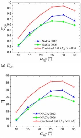
(a) COP
(b) η
Fig. 12. Comparison of (a) mean power extraction coefficient and (b) energy extraction
efficiency versus αeff at St = 0.4.
3.2 Effect of Strouhal Number
The variations of the mean power coefficient and the energy extraction efficiency as a function of the Strouhal number are shown in Fig. 11. It was found that both COP and η increase with St until a
maximum values at St = 0.3 and then decrease. The further increase of St causes an important decrease of the energy extraction performances. These results are explained by the good synchronization between the lift forces and the heaving motion at St close to 0.3. Conversely, for higher or lower values of St, the synchronization is weaker. Moreover, at high St number the energy consumed by the pitching motion increases rapidly compared to the energy extracted from the heaving motion. It was also noticed that at low Strouhal number (St < 0.2) the foil shape has a negligible effect on the energy extraction performance. But for St > 0.2, significant improvements of COP and η are found with the
combined foil.
3.3 Effect of the Angle of Attack (AOA)
The variation of the mean output power coefficient and the energy extraction efficiency according to the effective angle of attack is shown in Fig. 12. The Strouhal number was set to St = 0.4. For the three flapping foils, when the effective angle of attack increases, both COP and η increase first andbetween 25◦ and 35◦. Moreover, the mean output power coefficient and the energy extraction efficiency were found to be higher for the combined foil compared to NACA0006 and NACA0012 baseline foils for all angles of attack. This confirms that the combined foil shape can improve the energy extraction performance of a flapping foil.
4. C
ONCLUSIONIn this work, the energy extraction performance of a flapping foil device with a combined foil shape was investigated. The 2D unsteady and incompressible Navier-Stokes equations governing the flow over the foil undergoing prescribed heaving and pitching motions at low Reynolds number (Re = 10 000) were solved by a finite volume method, using the software ANSYS Fluent 16. The considered foil was designed by combining a NACA0012 leading edge and a NACA006 trailing edge. Then, the NACA0006 and NACA0012 were used as baseline foils. For this work, a validation study was carried out, and the results were in good agreement with the published data. Thus, the main results obtained in this study are summarized below:
1) The use of the combined foil improves the energy extraction performances.
2) The connecting area between the leading edge and the trailing edge (Xs/c) has a significant
effect on the energy extraction performance. Indeed, the best performance was observed at
Xs/c = 0.5, where the energy extraction
efficiency was improved by 30.60% and 17.32% in comparison to NACA0006 and NACA0012, respectively.
3) For the kinematic parameters considered in this study, it is also observed that the combined flapping foil extracts the energy mainly by the heaving motion, while the contribution of the pitching motion is negative.
4) Moreover, the flow fields over a flapping cycle show that the vortex and the pressure distribution near the trailing edge of the combined foil are changed. This is due to the stepped surface of the foil. Consequently, the lift force and the moment coefficient are enhanced, thus, the energy extraction performance is improved.
Accordingly, the combined foil shape may provide an effective means to improve the energy extraction performance.
R
EFERENCESAnderson, J. M., K. Steritlien, D. S. Barrett, and M. S. Triantafyllou (1998). Oscillating foils of high propulsive efficiency. Journal of Fluid
Mechanics 360, 4172.
Ashraf, M. A., J. Young, J. Lai, and M. Platzer (2011). Numerical analysis of an oscillating-wing wind and hydropower generator. AIAA J
49(7), 1374 – 1386.
Boroomand, M. and S. Hosseinverdi (2009). Numerical investigation of turbulent flow around a stepped airfoil at high reynolds number. In Fluids Engineering Division
Summer Meeting, Volume 1: Symposia, Parts A, B and C, pp. 2163 – 2174. ASME.
Davids, S. T. (1999). A computational and
experimental investigation of a flutter generator. Ph. D. thesis, Naval Postgraduate
School, Monterey, California.
DeLaurier, J. and J. Harris (1974). An experimental investigation o f the aerodynamic characteristics o f stepped-wedge airfoils a t low speeds. AIAA, 74 – 1015.
Fertis, D. G. (1994). New airfoildesign concept with improved aerodynamic characteristics. Journal
of Aerospace Engineering 7(3), 328 39.
Fogleman, F. F. and R. L. Kline (1972, 12). Airfoil for aircraft.
Guglielmini, L. and P. Blondeaux (2004). Propulsive efficiency of oscillating foils.
European Journal of Mechanics -B/Fluids 23(2), 255 – 278.
Jones, K. and M. Platzer (1997, December). Numerical computation of flapping-wing propulsion and power extraction. In 35th
Aerospace Sciences Meeting and Exhibit,
Reno, Nevada, Jan.
Kamyab, M. and H. Ghassemi (2017). Experimental study of flow field on stepped airfoil at very low reynolds number. Proceedings of the
Institution of Mechanical Engineers, Part G: Journal of Aerospace Engineering 9(231),
1706 17.
Kamyab, M., H. Ghassemi, and H. A. Arzideh (2016). Numerical study of the effect of geometrical changes on the airfoil aerodynamic performance. International
Journal of Fluid Mechanics Research 43(16),
28–38.
Karbasian, H., J. Esfahani, and E. Barati (2015). Simulation of power extraction from tidal currents by flapping foil hydrokinetic turbines in tandem formation. Renewable Energy 81, 816 – 824.
Kinsey, T. and G. Dumas (2008). Parametric study of an oscillating airfoil in a power-extraction regime. AIAA J 46(6), 1318 – 1330.
Kinsey, T. and G. Dumas (2012). Optimal tandem configuration for oscillating-foils hydrokinetic turbine. J. Fluids Eng 134(3), 31103 – 31103. Kinsey, T. and G. Dumas (2014). Optimal operating
parameters for an oscillating foil turbine at reynolds number 500 000. AIAA Journal 52(9), 1885 – 1895.
Le, T. Q., J. H. Ko, and D. Byun (2013). Morphological effect of a scallop shell on a flapping-type tidal stream generator. Bioinspir.
A. Boudis et al. / JAFM, Vol. 11, No. 6, pp. 1651-1663, 2018.
1663 Liu, W., Q. Xiao, and F. Cheng (2013). A
bio-inspired study on tidal energy extraction with flexible flapping wings. Bioinspir. Biomim
8(3), 036011.
Lu, K., Y. Xie, and D. Zhang (2014). Nonsinusoidal motion effects on energy extraction performance of a flapping foil. Renew. Energy
64, 283 – 293.
Lu, K., Y. Xie, D. Zhang, and G. Xie (2015). Systematic investigation of the flow evolution and energy extraction performance of a flapping-airfoil power generator. Energy 89, 138 – 147.
McKinney, W. and J. DeLaurier (1981). Wingmill: An oscillating-wing windmill. J. Energy 5(2), 109 – 115.
Simpson, B.J., S. L. F. H. and M. Triantafyllou (2008). Energy extraction through flapping foils. In ASME, 27th International Conference
on Offshore Mechanics and Arctic Engineering.
Usoh, C. O., J. Young, J. C. S. Lai, and M. A. Ashraf (2012). Numerical analysis of a non-profiled plate for flapping wing turbines. In
Proceedings of the 18th Australasian Fluid Mechanics Conference, Launceston, Australia.
Wang, Y., X. Sun, D. Huang, and Z. Zheng (2016). Numerical investigation on energy extraction of flapping hydrofoils with different series foil shapes. Energy 112(Supplement C), 1153 – 1168.
Wu, J., J. Wu, F.-B. Tian, N. Zhao, and Y.-D. Li (2015). How a flexible tail improves the power extraction efficiency of a semi-activated flapping foil system: A numerical study. J.
Fluids Struct 54, 886 –899.
Wu, T. (1972). Extraction of flow energy by a wing oscillating in waves. J.Ship Res 16(66). Xiao, Q. and Q. Zhu (2014). A review on flow
energy harvesters based on flapping foils.
Journal of Fluids and Structures 46, 174 –191.
Xiao, Q. and W. Liao (2010). Numerical investigation of angle of attack profile on propulsion performance of an oscillating foil.
Computers and Fluids 39(8), 1366 –1380.
Xiao, Q., W. Liao, S. Yang, and Y. Peng (2012). How motion trajectory affects energy extraction performance of a biomimic energy generator with an oscillating foil?Renew.
Energy 37(1), 61 – 75.
Xie, Y. H., W. Jiang, K. Lu, and D. Zhang (2016). Numerical investigation into energy extraction of flapping airfoil with gurney flaps. Energy
109, 694 – 702.
Young, J. and J. C. S. Lai (2007). Mechanisms influencing the efficiency of oscillating airfoil propulsion. AIAA J 45(7), 1695 1702.
Zhu, Q. and Z. Peng (2009). Mode coupling and flow energy harvesting by a flapping foil.