Science Arts & Métiers (SAM)
is an open access repository that collects the work of Arts et Métiers Institute of
Technology researchers and makes it freely available over the web where possible.
This is an author-deposited version published in:
https://sam.ensam.eu
Handle ID: .
http://hdl.handle.net/10985/9043
To cite this version :
Manuel PARIS, Paul EGLIN, François MALBURET, Jean-Claude CARMONA - Control loads
reduction through control system architecture optimization – application to a conventional rotor on
compound helicopters In: AHS 70th annual Forum, Canada, 201405 Forum 70 Proceeding
-2014
Any correspondence concerning this service should be sent to the repository
Administrator :
[email protected]
Control loads reduction through control system architecture optimization –
application to a conventional rotor on compound helicopters
Manuel PARIS
phD Student,
EUROCOPTER*, an EADS Company,
Marseille, FRANCE
Paul EGLIN
Aeromechanics engineer,
EUROCOPTER*, an EADS Company,
Marseille, FRANCE
François MALBURET
Associate professor at LSIS**,
Arts et Métiers ParisTech,
Aix-en-Provence, FRANCE
Jean-Claude CARMONA
Professor at LSIS**,
Arts et Métiers ParisTech,
Aix-en-Provence, FRANCE
Abstract
kinematic study of a helicopter main rotor control system is carried out to investigate loads in servo actuators and non-rotating scissors during high speed and high load factors maneuvers. The kinematic model is then used to optimize the servo-actuators placement and pre-inclination in order to minimize static and dynamic loads in the three servo-actuators and in the non-rotating scissors. The inputs for the model (blade pitch link loads and pilot input to trim the aircraft) are taken from flight tests measurements, current rotor computations being unable to predict blade root torsion moments vs azimuth with enough accuracy. The analysis is based on X3 demonstrator flight tests, which showed high control system loads that used to reduce flight envelope during the first flight test campaign. Flight tests measurements are used to validate the kinematic model used for the optimization. Computations made for X3 case at 220kts showed a reduction of 40% of maximum static load and 45% of maximum dynamic load on servo-actuators compared to the initial placement of the servo actuators. With appropriate servo actuators pre-inclination, dynamic loads in the non-rotating scissors are decreased by 95% at high speed trim flight. This paper shows how it is possible to keep a conventional rotor control system for compound helicopters. The optimization algorithm presented in this paper can be used for conventional helicopters to reduce loads in the control system and then limit command reinjection because of control system flexibility, and on compound helicopters to expand the flight envelope and to remove control system loads as the first limit factors at high speed.
(*) Eurocopter, an EADS Company, aéroport International Marseille Provence, 13725 Marignane Cedex
(**) LSIS : Laboratoire des Sciences de l’Information et des Systèmes, Domaine universitaire de Saint Jérôme, avenue Escadrille Normandie Niemem, 13397 MARSEILLE Cedex 20
Introduction
Over the last century, conventional helicopter has been the most economical way to combine vertical take-off and forward flight. Nonetheless, forward flight is limited at speed around 160 kts, due to two main limiting factors: high control system loads and rotor performance limitations. Eurocopter X3 proposes a new way to increase the speed, by adding two propellers and a short wing to decrease rotor lift and propulsion at high speed. In this way the performance issue is solved, but control system loads issue is still unsolved.
The increase in control system loads with the speed comes from the dissymmetry of velocity between the advancing and the retreating blade. As the cruise speed of a helicopter increases, the velocity on the retreating blade decreases and the velocity on the advancing blade increases. As the rotor is articulated, the lift on the advancing side and on the retreating side must be the same in order to trim the helicopter with a small roll angle. The pitch angle of the advancing blade must decrease and the pitch angle of the retreating blade must increase. On the retreating side, dynamic stall at the tip of the blade and leading edge flow attack on airfoils in the reverse flow region occurs. On the advancing side, compressibility effects due to a Mach number in the transonic region cause severe vibrations due to flow separation on airfoils. These effects imply an increase in blade root pitching moment that leads to high control system loads (control system loads issue). As the retreating blade lift drops with speed, the advancing blade lift drops as well, and the total rotor lift gets limited with the speed (performance issue). These two issues limit the flight envelope of rotorcrafts. For medium-weight helicopters (like Eurocopter Dauphin), both performance and loads in level flight issues appear around 160 kts. Eurocopter X3 demonstrator solved the performance issue by lowering lift needed from the main rotor, but X3 flight tests have revealed that servo actuators and non-rotating scissors loads increase rapidly with the speed and became a limit around 180 kts at the beginning of the first flight tests campaign. That means that the rotor could produce the lift needed to trim the aircraft (not a performance issue), but the loads in the control system are too high to go faster. Erez Eller, who works on Sikorsky X2 concept, also noted that speed of (compound) helicopters is limited because of loads and vibrations in the control system [1].
When the helicopter is flying forward, the flow due to the speed of the aircraft combines with the flow due to rotation on the blades. This creates an asymmetry in the velocity seen by the airfoils, which means that the pitch angle on each blade should vary over a rotation. To compensate the difference of velocity, the pitch angle over a rotation should change.
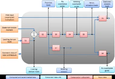
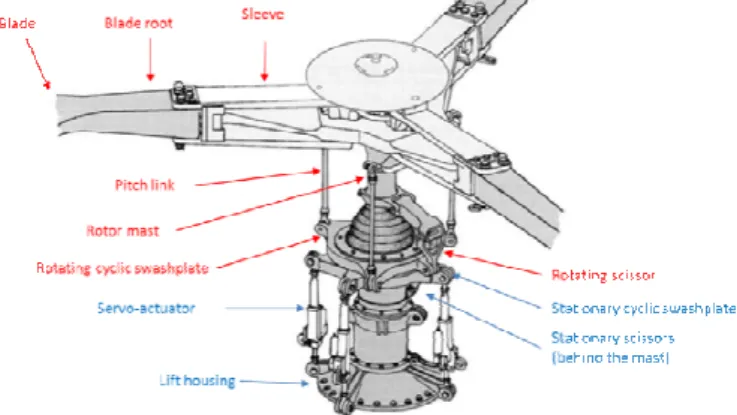
The control system mechanism used by most of helicopters to provide the pilot or AFCS pitch angle input to the blade is described Figure 1. The pilot commands is converted into a displacement order for the three servo actuators, which modifies the inclination and the position of the swashplate. As noted by G.D. Padfield [2], the swashplate is a “key innovation in helicopter development”, by converting displacement into angles at a frequency of 1/rev.
A collective pilot pitch input creates the same displacement on the 3 servo-actuators, leading the cyclic swashplate to translate parallel to the rotor mast in order to increase or decrease by the same angle the pitch of all blades. A cyclic pitch input will lead to differential displacement on servo-actuators in order to tilt the swashplate. The combination of cyclic and collective inputs with velocity dissymmetry on rotor disk leads to unsteady airloads on the blades, which will allow maneuvering the aircraft. A force feedback enters the control system back through the pitch links. This force is then transmitted back to cyclic swashplates, servo actuators and non-rotating scissors. The servo actuators must withstand this force, in order to maintain the cyclic swashplate at the right position and inclination. The increase of servo actuators and non-rotating scissors loads with speed is the major concern in control system loads.
Figure 1 : Main rotor description
It should be noted that the servo actuators do not control the cyclic swashplate inclination dynamically: servo actuator displacement are slow (less than 1 Hz for pilot needs). In aircraft trim conditions, no servo actuators displacement is needed (no inclination and no displacement of the cyclic swashplate). As the command is given in the non-rotating frame to rotating frame, a 1*Ω dynamic pitch input is applied on each blade. A lot of research is conducted on Higher Harmonic Control (HHC), including [3], which is achieved with a harmonic motion of servo actuators displacement. HHC aimed to reduce vibration by controlling blades pitch angle on a frequency higher than 1*Ω. The HHC is not the topic of this publication, but the load reduction obtained in this publication will help to set up HHC on helicopter rotors.
In order to reduce the loads in the control system, 2 main solutions are possible:
• Reducing pitch link loads
• Change the control system architecture
As noted previously, 3 aerodynamic phenomena may increase blade root pitching moment:
• Compressibility on advancing blade
• Aerodynamic center shift in the reverse flow region on retreating blade
• Dynamic stall on retreating blade
These phenomena, associated with the blade dynamic behavior lead to high control loads for high advance ratios.
When dynamic stall occurs at the tip of retreating blade, a vortex is created near the leading edge of the airfoil, and then is conducted downstream. When it leaves the airfoil upper side, a huge increase in moment appears. Propagating along the blade, this moment increases the total moment at the blade root. When the aircraft is flying forward, a reverse flow region appears next to the blade root. In this region, the airfoils are attacked by the trailing edge side, which moves the aerodynamic center to 25% of the chord starting at the trailing edge. This phenomenon increases the moment around the pitch axis because of the increase in the lever arm between the aerodynamic center and the pitch axis. A current study on X3 flight tests aims to determine the contribution of each phenomenon to the total blade root moment.
The current issue for the prediction is about the aerodynamic modeling of dynamic stall on the retreating blade and the attack of airfoils by the leading edge in the reverse flow region. Moreover, the dynamic response of the blades to these phenomena is not well modeled. These phenomena have been the topic of several publications, since T. Theodorsen in 1935 [4], who proposed the first model for dynamic stall. F.J. Tarzanin [5] proposed a new dynamic stall model and computed pitch link loads according to this model. Figure 2 is extracted from his publication, and shows how well Tarzanin’s model can match experimental results.
Figure 2 : Tarzanin’s dynamic stall modeling results (1972) from [5] Nonetheless, even if it improves the current dynamic stall computation model, a small discrepancy of approximately 20 deg appears for the 2 peaks representing the dynamic stall process of detached and reattached flow. If the point of 400 deg is considered, the experiment gives a maximum and Tarzanin’s model gives a 0-value. This small error in blade azimuth position implies changes in main rotor head screw and then loads in control system. In 1997, William G. Bousman [6] considers that the current ability to forecast dynamic loads on the blades and on the rotor is not sufficient to get satisfactory results. As blade unsteady aerodynamics is not well modeled in numerical computations, it is not possible to get fair results either for lead-lag loads or for pitching moments.
As it is not possible currently to have results fair enough for pitch link loads computation, these loads will be considered as input for the optimization algorithm. Nonetheless, the task to improve blade root loads prediction is part of the main issue of reducing control system loads on compound and conventional helicopters.
Currently, servo actuators on light helicopters are placed on pure control axis, i.e. the pitch command results in an order on the servo actuator(s) located on the cyclic swashplate pitch axis and the roll command results in an order on the one located on the cyclic swashplate roll axis. In the case of X3, the main rotor come from the Dauphin family; the pitch is controlled by 1 servo actuator and the roll is controlled by 2 servo actuators located at 180°. Th e angle between a pitch servo actuator and a roll servo actuator is 90°. If servo-actuators are not on these pure contr ol axis, a mechanical part named mixing unit has to be used to convert pilot command into servo-actuators displacement through lever arm combination. A pure pitch or a pure roll input from the pilot will lead to mixed displacement of the 3 servo actuators. The azimuthal placement of servo-actuators is based on the available room near the rotor; as the rotor is one of the most important focuses of drag for a helicopter, the size of the rotor should be kept to a minimum in order to lower total drag of the rotorcraft. The present paper gives another constraint based on compound flight test results: placement of servo-actuators should take into account loads optimization in the control system.
The issue of reducing control system loads considering reconception process has not been the concern of many publications. The reason is that control system loads on conventional helicopters are considered with an empirical point of view in the industry. The numerical models are not able to predict them, and these loads are not the factor that limits performance of conventional helicopters, even though important loads appear at high speed and severe maneuvers. With the emergence of hybrid helicopters and rotors that have to operate at high speeds, blades loads increase, so do the control system loads.
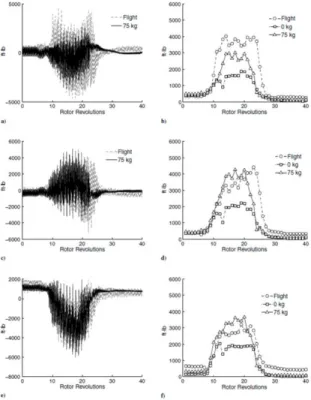
Blade loads in severe conditions (turn at high load factor, pull-up maneuver) for conventional conditions have been the topic of a lot of research work. A. Abhishek [7] showed that blade loads, pitch link loads and servo actuator loads increase during these severe maneuvers. The Figure 3 shows that both static and dynamic loads increase.
The same observation has been made by M. Voskujil [8] on the increase of pitch link loads which causes high loads in the control system. He notes that a fair kinematic model and the stiffness of control system leads to good results. This highlights that command reinjection due to high pitch link loads might be an issue in rotor loads computation. Reducing control system loads (more particularly servo actuators loads) will help to avoid command reinjection. R.M. Kufeld & W. Johnson [9] demonstrated that a combination of low stiffness and high loads lead to premature dynamic stalls.
K. Nguyen [10] carried out a study about control system loads with a higher harmonic control command as a function of blade stiffness. This HHC aimed to vibrations suppression and increase of performance, not the reduction of the control loads. Figure 4 shows that such an HHC command leads to identical dynamics loads at blade root with or without the HHC command. Figure 5 shows that (for a blade whose natural frequency is 4.86Ω) the pitching moment on the
side shows an increase in this moment because of delayed dynamic stall, which makes it even stronger.
Figure 3 : Servo actuators loads. Document from Army/NASA UH-60A Airloads Program Flight Counter 11029. Graphs a), c), e): servo actuators loads during the pull-up maneuver. Graphs b), d), f): servo actuators dynamic loads during the pull-up maneuver [7].
Figure 4 : K. Nguyen study results on the peak-to-peak normalized blade root pitching moment with a HHC command [10] D.O. Adams [11] proposes the use of a spring/damper system for the pitch link in order to damp dynamic stall effect in the control system at high frequency. The results given in his paper show a significant reduction of control system loads, without altering aircraft maneuverability. This proposal can be taken into consideration in the kinematic model described in this publication, in order to increase the accuracy of the optimization process. Nonetheless, production and maintenance problems may arise from such a solution, which may explain that no conventional helicopter use this technology nowadays.
R.B. Taylor [12] investigates a new method to evaluate empirically control system loads and then to determine structural limits of the flight envelope. The aim is to predict at
the pre-design stage control system loads to allow designing control system without limiting flight envelope because of unexpected control system loads. This is what is done nowadays to size a control system, as numerical computation is not able to predict control system loads accurately.
Figure 5 : K. Nguyen study results on normalized blade root pitching moment with a HHC command [8]
The DLR (Deutschen Zentrums für Luft- und Raumfahrt) took part of the blade root pitching moment issue at high speed by using Leading Edge Vortex Generators (LEVOG’s) at blade tip. When the big dynamic stall vortex is created, it is conventionally convoyed downstream and produces a high pitching moment when it leaves the extrados. The idea with the LEVOG’s is to break this big vortex into small transverse ones, which will bring energy back into the boundary layer to get the flow reattached faster on the extrados.
The major difference between these publications and patents should be highlighted at this point: the goal of this publication is not to reduce blade root pitching moment, even though that will reduce control system loads. The goal here is to reduce the loads in the control system by designing the control system architecture in order to better spread cyclic plate loads on the 3 servo-actuators and in order to reduce non-rotating scissors loads.
This bibliography highlights the need to reduce control system loads, for conventional as well as compound helicopters. Nonetheless, it appears that the current knowledge on rotor blades dynamics and aerodynamics is not sufficient to find a way to reduce significantly the pitching moment at blade root. The solution proposed in this paper is to lower control system loads by changing servo-actuators placement. The bibliographic study for this publication found no record of such a work even though the optimization algorithm can be used for most of current conventional helicopters.
Another point of interest of high loads in control system is due to the flexibility of mechanical parts and the possible reinjection of command. As noted by Kufeld and Johnson [9], the control system stiffness has an impact on dynamic stall. High loads in the control system combined to low control system stiffness leads to command reinjection in the blade pitch, which make dynamic stall appear earlier.
The major objective of this paper is to propose a new method to choose servo-actuators architecture in the control
system. This method is an optimization of the architecture in order to reduce static and dynamic loads in servo actuators and non-rotating scissors for a given flight condition. A broader method is also given to take into consideration the all flight envelope of the aircraft and hence to get the best architecture.
The origins of control system loads will be first examined. A kinematic model is computed in order to ensure that every phenomenon participating to servo actuators and non-rotating scissors has been clearly identified. This model shows that shocks in non-rotating scissors appear in the joint at high speed, and avoiding shocks is turned to be a new concern for the optimization. The optimization algorithm (based on a least square method) on the kinematic model and the choice of optimization criteria are exposed. The kinematic model will also be used to compute loads that can’t be measured, like the screw (forces + moments) at the center of the cyclic swashplate. The optimization process is validated with an example based on X3 flight tests at 220 kts. The last step proposes an optimization logic considering the whole flight envelope. This publication is a part of a wider program aimed to understand, predict and minimize control system loads based on X3 flight tests. The future work in this program will be mentioned at the end of this paper.
Even though the case study is a compound helicopter in this paper, the optimization proposed here can be applied to conventional helicopters in order to avoid high control system loads.
Norms
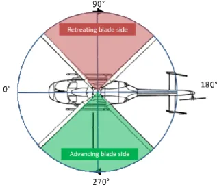
The analysis is based on azimuthal position of servo-actuators, pitch links and blades. The norm taken into account in this publication is represented Figure 6.
The pitch is commonly expressed by equation (1.1).
(1.1)
Pitch link loads analysis
The control system receives a command which is a combination of pilot input through the cyclic stick and AFCS input, which modifies servo-actuators displacements. When collective or cyclic pitch is applied, aerodynamic loads on blade change and blade torsion loads change as well.
The root blade pitching moment has 2 main origins:
• Summation of aerodynamic and inertial moments on airfoils along the blade (from the tip to the root)
• Moment created by lead-lag damper loads
Figure 6 : Azimuthal position norm
The aerodynamic flow on the blade creates lift, drag and pitching moment on airfoils along the blade. The blade root drag load is the integration of all drag forces along the blade. As the blade is free in lead-lag direction, the blade root drag load comes into the damper. In reaction the damper creates a moment through the lever arm between its axis and the blade pitch axis, as noted Figure 7.
Figure 7 : Lead-lag damper induced pitching moment The most important part of pitch link loads comes from the blade root pitching moment. The blade root pitching moment is the integration of aerodynamic pitching moment on airfoil along the blade. Based on aerodynamics theory for attached flow, the moment acting on an airfoil is constant at the quarter chord point (aerodynamic center), unless the flow is not attached on the airfoil (static stall) or if dynamic stall occurs, because the aerodynamic center is shifted to the 50% chord point. The equation to compute linear moment on an airfoil around the aerodynamic center is given equation (1.2).
(1.2)
In hover, all blades have the same pitch angle and the velocity distribution is axisymmetric around the mast axis. As moment coefficient is constant when angle-of-attack changes for attached flow, the blade root pitching moment does not depend on the mass of the aircraft, it depends on blade geometry (mean blade chord c). The value of depends on the airfoil definition (camber, thickness distribution)
sleeve
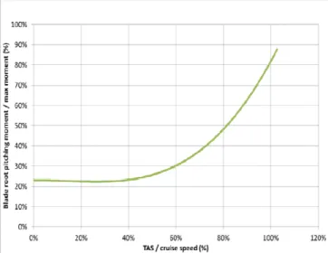
In low speed flight, when no unsteady aerodynamics and no reverse flow region occur on the blade, the blade root pitching moment value depends on blade azimuth because of velocity distribution on the rotor disk. In high speed flight, dynamic stall and reverse flow region on the retreating blade change the value of , as well as compressibility effects on the advancing side. Figure 8 shows results obtained on a conventional helicopter for blade root pitching moment versus forward speed.
Figure 8 : Dynamic peak-to-peak blade root pitching moment versus forward speed
Control system loads origins
The first step to create the optimization algorithm is to get the kinematic model of the control system. In this paper, the code of the algorithm will not be presented, the origin of the loads in the concerned control system mechanical parts are exposed.
Rotating scissors
Loads in rotating scissors come from orthographic projection of pitch link loads on the rotating swashplate plane. The axial load in the pitch link can be projected on the swashplate in a radial force toward the mast axis and in a tangential force; the latter is converted in the rotating scissors loads through the lever arm.
Cyclic swashplates
The 5 pitch link loads combine on the rotating swashplate in order to set the screw at the center of the rotating swashplate (given by equation (1.3)).
(1.3)
The moment Mz around the mast axis is not transmitted to the non-rotating swashplate because of the bearing linkage. The forces FX and FY create a force perpendicular to the mast and do not affect the non-rotating swashplate. Therefore, the screw at the center of the non-rotating swashplate is given by equation (1.4).
(1.4)
This screw at the center of the non-rotating swashplate is difficult to get through measurements. Nonetheless it’s an important data to size the swashplate and to understand the behavior of the force acting on it during one rotor rotation. This screw is broken down as a normal force Fz acting at a distance xF of the axis y and yF of the axis x. (point of force application coordinates: (xF,yF)).
et (1.5)
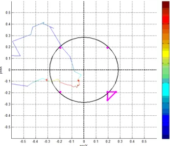
Figure 9 shows the evolution of the position of the point of force application and the norm of the force during a complete rotor rotation. The upper diagram is the 2D view; the lower diagram shows the position of control system mechanical parts in 3D.
Figure 9 : Graphic representation of swashplate screw Servo actuators
In order to maintain the non-rotating swashplate in position, the screw at the center of the non-rotating swashplate is spread on the 3 servo actuators, according to
their azimuthal position on the swashplate. The servo actuators are gimbaled at their tips, the only unknown in the equation is then the axial force. The system is statically determinated and the loads in servo actuators can be derived directly from the swashplate screw.
Non-rotating scissors
Non-rotating scissors loads come from tangential loads created by servo actuators axial loads orthographic projection on the swashplate plane. Figure 10 shows the force balance on the swashplate for a swashplate tilted case. When the servo actuators are not perpendicular to the swashplate, only the component parallel to the mast axis is used to maintain the swashplate. The projected forces R1, R2 and T (on the lower diagram) are linked to the angle between each servo actuators and the swashplate. The force balance shows a shear stress in the scissors in order to lock the rotation of the swashplate.
The force in a servo actuator is given by equation (1.6).
(1.
Figure 10 : Non-rotating scissors loads origin
Kinematic model
Figure 11 : Global diagram of the kinematic model The computation model is based on control system kinematics. The main objective is to provide servo actuators axial loads and non-rotating scissors shear stress starting with pitch link loads signal and an architecture description of the current control system. This algorithm can be used to get rid of sensors on servo-actuators and non-rotating scissors. A diagram of the kinematics model is given Figure 11, with the inputs and the outputs provided. Subsystems allow the user to get some intermediate forces; the most interesting of them is the screw at the center of the non-rotating swashplate. The diagram shows also the variables used for model validation.
Model validation
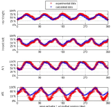
During flight tests, servo actuators and pitch links and non-rotating scissors were equipped with strain gauges that can provide stresses in these mechanical parts. In order to validate the kinematic model, computed and measured loads values on servo actuators axial force and non-rotating scissors shear stress are compared Figure 12 for a high speed flight condition. Measured pitch link loads were used as an input to the kinematic model. The swashplate tilt angles (position and inclination) are needed to compute scissors shear stress. These angles are a combination of pilot inputs and AFCS (Automatic Flight Control System) input on the SEMA (Smart Electro Mechanical Actuator).
The Figure 12 shows a fair correlation for servo actuator loads in the time domain. But the shear stress in the non-rotating scissors is underestimated by the kinematic model. For low speed measurements, the correlation is better than for high speed conditions. The shear force measurement in the non-rotating scissors presented Figure 12 shows a different signal shape than the signal measured at low speed. When the signal reaches a 0-value, a step in the signal appears for several degrees before increasing with a higher slope than expected. This phenomenon can be explained by shocks in the linkage between the scissors and the swashplate. When the shear force sign changes, the scissors changes its support surface, but the presence of clearance in the linkage and the stiffness of mechanical parts
Lateral view
front
result in a 0-value in the shear stress signal and then a higher shear force due to impact force.
Figure 12 : Measured and computed loads in control system To confirm this hypothesis, an experience has been conducted during X3 flight tests. The clearance has been reduced to 0 by adding thin washers. The results of this experience are given Figure 13 (flight test results are smoothed on the diagram).
Figure 13 : Non-rotating scissors shear stress with and without clearance
Without clearance, Figure 13 shows that the increase in non-rotating scissors shear force is more linear than with clearance. Before reaching 85 % of the maximum cruise speed, the dynamic load in the non-rotating scissors is lower than expected, because the scissors is in the clearance. When the kinematic dynamic load is high enough to create enough acceleration on the scissors in the linkage, the shock appears (around 85% of the maximum cruise speed) and the loads increases rapidly. Above 85% of the maximum cruise speed, the scissors are working with shocks and the kinematic loads increases (as shown on the curve without clearance). This experience shows that high dynamic loads in the non-rotating scissors lead to shocks in the linkage, which is not acceptable for a nominal use.
In the frame of modeling the control system, an empirical model for shocks has been integrated to the first kinematics model. This model is based on a Newton’s second law to get the speed of the scissors upper attach on the swashplate at the moment of impact, and on a second order system model to determine the force created by the shock. For the optimization process, this shock model is useless because the non-rotating scissors loads will be reduced by a significant amount that cannot create shocks in the linkage.
Optimization for a flight condition
The first step in the optimization process is to get the architecture that will give the lowest servo actuators and non-rotating scissors loads for a given flight condition. The next step will be to find the trade-off between several optimization results for several flight conditions inside the aircraft flight envelope.
The objective is to place and incline servo actuators in a way that the optimization criterion is the lowest as possible. The flight conditions inputs are:
• Pitch link loads signal for a complete rotor rotation;
• Pilot and AFCS inputs for blade pitch angle.
Along with them, rotor architecture variables that cannot be changed are inputs of the algorithm, as well as the degree of freedom allowed in the azimuthal position for servo actuators. A common degree of freedom is to place the servo actuators on the pure command axis (without a tolerance of ± 5°) in order to avoid the use of a mixing unit in the control system. In order to be statically determined, three servo actuators are used to hold the swashplate, and 4 positions are available with this case study (2 for roll and 1 for pitch control / 1 for toll and 2 for pitch control). The optimization algorithm will determine the number of servo actuators on the roll command axis and on the pitch command axis, as well as the placement of the servo actuator within the interval.
The optimization is broken down into 2 phases. The first one aims to reduce static and dynamic loads on servo actuators by optimizing the azimuthal placement of the actuators around the swashplate. The second one aims to reduce non-rotating scissors static and dynamic loads by pre-inclining the servo actuators.
Servo actuators placement
The objective of the first phase of the optimization is to better spread the swashplate screw on the 3 servo actuators, in order to lower the maximum loads.
Optimization variables
The optimization variables are the static and the dynamic loads in the 3 servo actuators, which lead to 6 optimization variables. The total loads signal is composed by a fundamental frequency and harmonic terms. In this analysis, the static value and the dynamic value (peak-to-peak value) will be taken into consideration. According to Figure 12, the b*Ω frequency is the main component of servo actuators and non-rotating scissors loads.
Optimization criteria
Servo actuators are hydraulic components with reversibility threshold. If this threshold is overpassed by the loads, the swashplate inclination will be uncontrollable as well as blade pitch angle and the aircraft will become un-flyable. It is a design constraint to get static loads in the actuators below the reversibility threshold. On the other side, dynamic loads in actuators lead to fatigue in the mechanical parts. If the parts get damaged because of high dynamic loads, they have a reduced lifetime and lead to maintenance issues. Dynamic loads reduction is important, but not as much as static loads.
Another constraint has to be taken into consideration in the algorithm: the use of the 3 same servo actuators in order to reduce cost (purchase and maintenance costs). The loads must be fairly distribute on the 3 servo actuators, in order to get the lowest maximum static and dynamic sizing loads for servo actuators design.
Thanks to this analysis, the 4 parameters to optimize are:
1. Difference on static loads between the most loaded and the less loaded servo actuators
2. Difference on dynamic loads between the most loaded and the less loaded servo actuators
3. Summation of the static loads on the 3 servo actuators
4. Summation of the dynamic loads on the 3 servo actuators
Weighting coefficients are attributed to each of these criteria. They are determined empirically thanks to the importance given by the designer of the optimized control system. The objective of the optimization is to find the combination of servo actuators placement that minimize with a least square procedure these 4 weighted coefficients.
Optimization constraint
Some constraints are taken into account in the algorithm. As the rotor area where servo actuators are is crowded, some azimuthal positions might be non-available to place the servo actuators. The available position must be given to the algorithm in order to find the best possible placement.
This option is also used to get the algorithm to find the best place for servo actuators around the pure control axis. In this way, no mixing unit is needed in the control system. An interval of tolerance is also an input in this case and must be linked to the maximum allowed coupling between the roll input and the pitch input through the pilot cyclic stick.
Optimization strategy
An optimization strategy is necessary for such a computation, the number of cases being important. For example, in the no-constraint case, if the computation step is 1 deg, the number of cases to be computed is 3603/2 (which is above 23 millions of case to be computed). The computation time is too long, another strategy must be implemented.
The computation will be done in 2 steps. The first one is a rough step, where the computation step is 5°, wit h an interval between 2 servo actuators of at least 45°. From this computation an optimal placement is extracted. Then a computation around this position is done with a step of 1° on an interval of ± 5° around the previous placement. Then the optimum placement can be determined.
Servo-actuators pre-inclination
Pre-inclination is defined as the implantation angle of the servo-actuators with the perpendicular of the swashplate when the swashplate is horizontal. The shear stress in the non-rotating scissors is the only optimization variable. Moreover, as the relationship between servo actuators loads and scissors loads is kinematic, a decrease in static loads is linked with a decrease in dynamic loads.
As explained previously, the shock behavior in the non-rotating scissors should be avoided for standard flight conditions. The way to solve this problem is to decrease the dynamic loads in the non-rotating scissors and not filling the clearance with washers (as was done for the experiment). Figure 13 shows that even though shocks increase the peak-to-peak loads in the scissors, the kinematic force (given by the curve “without clearance”) reaches high value at high speed. The goal of this optimization is then to decrease the value of the kinematic dynamic load.
As non-rotating scissors loads are not influenced by the azimuthal position of the non-rotating scissors, no constraint has to be taken into account in this optimization other than scissors radial position. The qualitative study of non-rotating scissors loads shows that in order to have no non-rotating scissors loads, the servo actuators must be perpendicular to the non-rotating swashplate. For a given flight condition, the optimized pre-inclination of servo actuators is the value of the pitch angle command and of the roll angle command.
In forward flight, the roll command (θ1c) is near 0-value
but the pitch (θ1s) command is not 0 in order to trim the aircraft. When the aircraft roll rate is not 0, the roll command is not 0 with a different sign for a right turn or a left turn. Then no pre-roll angle should be used for servo actuator set up, because tilting servo actuators for a type of turn will increase the projection angle for the other type of turn, which doesn’t make sense according to the optimization logic. Then the servo actuators shouldn’t be tilted around the roll axis, they should stay neutral.
On the whole flight envelope of a helicopter, the value of pitch command varies. The flight conditions that bring the more servo actuators loads are high speed conditions, high load factor turn and pull-up maneuver. For these flight conditions, the cyclic pitch command is negative (decrease of the blade root pitch angle on the advancing side). The analysis conducted for this paper leads to a value around 80% of the pitch command angle needed to be in a trim flight at VH (maximum cruise speed).
General logic for a flight condition
The method for the optimization for a given flight condition is the following:
• First step: Optimization of servo actuators azimuthal position. This step aims to reduce loads in the servo actuators
• Second step: Pre-inclination of the servo actuators of the value of 80% of the pith command angle needed to be in a trim flight at VH.
• Third step: Computation of the loads in the non-rotating scissors for this flight condition
In this method, the swashplate screw is useful to get a graphic representation of the force acting on the swashplate, and can be used as a validation step for the results given by the algorithm. This screw does not depend on servo actuators placement, but on pitch link loads and rotor architecture.
Case studies results and discussion
The case study for this paper is based on a flight test at 220 kts on X3 demonstrator, which is the standard cruise speed for this compound helicopter. X3 demonstrator is built of parts of other EC helicopters, the main rotor is the one of the Dauphin family. For such an aircraft, the optimization algorithm presented in this paper is particularly useful because the behavior of compound helicopters blade at high speed is different from the blade behavior for a conventional use.
In order to show the abilities of the algorithm, 3 different cases are presented in the following:
• Case study n°1 : 2 consecutive servo actuators are constrained to be separated by an angle of 90°. Thi s constraint doesn’t have any physical reason, but this case allows drawing 2D graphs in order to validate the algorithm (the logic of this case is discussed further in this paper);
• Case study n°2 : No constraints are taken into account. The results of this case are the best azimuthal position for the servo actuators in order to minimize the criteria;
• Case study n°3 : The control system should avoid a mixing unit. This constraint is translated by servo actuators azimuthal position located on pure control axis with a ± 10° interval (in order to avoid impor tant coupling in the pilot stick).
Before dealing with these 3 cases, the cyclic swashplate screw is analyzed with blade pitch links measurements. The results are given on Figure 14, with the front of the aircraft in positive y-axis (variable posX) and the right of the aircraft in positive x-axis (variable posY) (view from above of the cyclic swashplate). This graph shows that the position of the front right servo actuator should be reconsidered to minimize servo actuators loads. This graphic shows also the initial position of servo actuators and the non-rotating scissors: 2 servo actuators for roll and 1 for pitch control.
Figure 14 : Cyclic swashplate screw and initial servo-actuators and non-rotating scissors placement for the case study
Case study n°1
It has to be clear that this case is used to represent graphically the method of optimization. Indeed, the load at time “t” in a servo actuator depends on cyclic swashplate screw as well as other servo actuator placement. The idea is to force the placement of the servo actuators to be linked by a constant value. In this case study, the value of 90° is the non-rotating value between 2 consecutive servo actuators. This constraint implied that the values of the azimuthal position of the second and third servo actuators are linked to the value of the first. In terms of representation, the no constraint condition leads to a 4D graph (positions of the 3 servo actuators scales + loads scale), when the fix-angle constraint leads to reduce the 3 scales needed for the position to one scale considering the position of the first actuator.
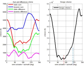
Figure 15 shows the results obtained for this case study. The 4 criteria are given in the graph on the left, when the design criterion (square root of the sum of the square weighted criteria) is drawn on the right of the graph. The curves are plotted versus the azimuthal position of the first servo actuator. The graph on the right shows a minimum value for the design criterion at 130 deg.
For this first case study, the results of the optimization are the following:
• Optimal placement of servo actuators : 131deg, 221deg and 311deg (as shown Figure 16 )
• Maximum static load evolution : - 40%
• Maximum dynamic load evolution : - 45%
• Criteria evolution
o Difference on static loads : - 31 %
o Difference on dynamic loads : - 35 %
o Summation on static loads : - 18 %
Figure 15 : Criteria versus first actuator placement The position of the non-rotating scissors shown Figure 16 is based on the available placement thanks to the new azimuthal position of the servo actuators.
Figure 16 : Case study n°1 - results
The results of the first case study shows how the algorithm works and the utility of the cyclic swashplate screw in order to check the results. The right graph of Figure 15 shows the evolution of the design criterion between previous position (x = 225deg – blue line) and the best position (x = 130deg – red line). By just moving the front right servo actuator to the rear position, the decrease of the loads in servo actuators is important.
Case study n°2
In this case no constraint is taken into account; the azimuthal position of the servo actuators is free. The optimization gives results for the first step of the optimization (computation step: 5 deg). These results have to be refined by reducing the computation step and to restraint the possible interval for servo actuator placement around the previous placement. The final results for this optimization are:
• Optimal placement of servo actuators : 131deg, 221deg et 311deg
• Maximum static load evolution : - 40%
• Maximum dynamic load evolution : - 45%
• Criteria evolution
o Difference on static loads : - 31 %
o Difference on dynamic loads : - 35 %
o Summation on static loads : - 18 %
o Summation on dynamic loads : - 43 %
Case study n°3
This last case study considers the constraint not to have a mixing unit in the control system, which can be translated by forcing the azimuthal position of the servo actuators to be around the pure control axis. The interval chosen for this case study is ± 10° around the pure command axis. T he results obtained for this optimization are the following:
• Optimal placement of servo actuators : 131deg, 221deg et 311deg
• Maximum static load evolution : - 40%
• Maximum dynamic load evolution : - 45%
• Criteria evolution
o Difference on static loads : - 31 %
o Difference on dynamic loads : - 35 %
o Summation on static loads : - 18 %
o Summation on dynamic loads : - 43 %
Servo actuator pre-inclination
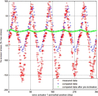
For a given flight condition, the solution to have no loads in the non-rotating scissors is to have the servo actuators perpendicular to the cyclic swashplate in the pitch axis and the roll axis direction. As explained previously, no pre-inclination in roll is applied since the roll angle depends on the direction of the turn. In the pitch axis direction, the servo actuators are pre-inclined by the value of the cyclic swashplate pitch. Results obtained for the case study n°2 servo actuators placement are shown Figure 17.
The loads in the non-rotating scissors are decreased by 95% after pre-inclination of the servo actuators. The dynamic loads are too small to induce shock behavior in the linkage, so the real signal will not be higher compared to the kinematic signal.
Conclusion about the cases studies
Considering the flight test conditions for a trim flight at 220 kts, the optimization leads to 3 servo actuators on pure control axis, even for the “no-constraints” optimization. This shows that the 120deg between servo actuators condition is not the best architecture to minimize servo-actuators loads during this trim flight. The optimization has been made for several case studies between 200kts and 230kts, and the result of the optimization is still the same.
Figure 17 : Servo actuator pre-inclination optimization
Optimization for a flight envelope
The last issue tackled in this paper concerns the application of such an optimization to an aircraft taking into consideration its flight envelope. The previous paragraph allow to optimize the servo actuator placement and pre-inclination for a given flight condition, thus for a given set of pilot inputs and blade pitch link signal. As placement and pre-inclination of servo actuators can’t be changed according to the flight condition, the chosen control system architecture has to reduce design loads over the entire flight envelope. Design loads are loads considered in sizing the system, which are the maximum loads and the sizing spectrum for fatigue.
This issue is linked with the existence of sizing flight conditions for the control system loads. The key factors are pilot inputs for non-rotating scissors loads and blade pitch link loads for servo actuators loads. As the cyclic swashplate inclination (given by the pilot inputs) can be counteracted by the use of servo actuators pre-inclination, it should be verified that tilting the servo actuators to get them perpendicular to the cyclic swashplate for high speed condition will not lead to high control loads at low speed. This depends on the value of pitch link loads and the loads in servo actuators.
For hover conditions, pitch link loads are constant over a rotor rotation and is low because the pitch axis and the aerodynamic moment of airfoils along the blade are merged. This leads to low servo actuators loads and then low non-rotating scissors loads even if the pre-inclination between servo actuators and the cyclic swashplate is important.
As speed increases, the moment at the blade root increases slightly as well as the drag force, leading to a constant and low value of pitch link loads until 40% of the maximum cruise speed, as Figure 8 shows. Then the increase becomes important after 60% of the maximum cruise speed. At this speed, the value of the cyclic longitudinal pitch angle is already high, and tends to increase in order to reach 100% at the cruise speed. In order to
decrease the maximum dynamic loads in the non-rotating scissors over this range (60% to 100%), the use of flight tests data and the optimization algorithm showed that the value of cyclic longitudinal swashplate necessary to reach 80% of the cruise speed leads to the best trade off. As this pitch angle value change with flight conditions (altitude, position of the center of gravity …) an average value should be taken into consideration.
The loads in servo actuators depend only on the swashplate screw. Figure 18 shows the evolution of the blade pitch link loads over a complete rotor rotation for flight conditions at cruise speed. The swashplate screw is drawn by considering this signal and the angle between 2 consecutive blades. As speed increases, the double peak located between the retreating blade and the aft blade increases in terms of amplitude, and gets more negative for the first peak and more positive for the second one. This condition creates a pure moment screw which will create higher loads in servo actuators. A pure force screw will spread on the 3 servo actuators, where the pure moment will involve in the worst conditions 2 servo actuators in compression and 2 servo actuators in traction. This mechanism is validated by flight test measurements during the X3 campaign.
Figure 18 : Blade root torsion moment for cruise speed This double peak finds its origin in unsteady phenomena, such as dynamic stall at the tip or trailing edge attack of airfoils at the root of the retreating blade. These phenomena appear for 2 different reasons: high speed and/or high load factor, for example in severe turns or pull-up maneuvers. X3 experience showed that severe turns at a load factor of 2G at 80% of the maximum cruise speed and cruise at maximum cruise speed are the conditions that bring the higher pitch link loads.
The next section aims to find the trade-off between the results given by the 2 optimizations. Nonetheless, it should be kept in mind that both sizing conditions will suffer the expected phenomena: dynamic stall and reverse flow. These phenomena happen in the same region of the rotor disk (between the retreating blade and the aft blade), but the dynamic stall might be delayed slightly according to the flight condition. So the screw at the center of the swashplate has the same shape in both cases, which leads to approximately the same results for the optimization. In this case, the trade-off between the 2 sets of results is easier.
Future work
This paper presents an algorithm to compute loads in the control system and propose an optimized architecture that minimizes control system loads. Blade pitch link loads are an input to this algorithm, taken from flight tests measurements in this paper.
The algorithm aims to be used at the pre-design stage, so the prediction of control loads becomes a key point, as well as the need to reduce them. The current issue is the modeling of the dynamic stall at the tip of the retreating blade, and the ability to predict accurately the aerodynamic moment of stall and the moment when the flow re-attach the airfoil extrados. The other predicted data is the pilot inputs for a flight condition (for the cyclic swashplate inclination); these data are well computed by current numeric computation tool HOST used at Eurocopter.
X3 flight tests have shown a sharp increase in the blade pitch link loads, which causes an important increase in servo actuators as well as non-rotating scissors loads. The installation of strain gauges on blades allows measuring blade elastic moment in torsion, flapwise bending and chordwise bending. The use of these measurements will lead to improve the aerodynamic computation, and then to estimate the loads in the control system at the draft stage for new aircrafts.
Conclusions
The X3 demonstrator has shown that it is possible to fly a conventional rotor at high speed while keeping excellent handling qualities and lift-to-drag ratio. This is a key factor which allows using the same rotor for a family concept covering conventional and high speed helicopters.
However the high speed flight leads to a level of stress in prolonged flight phases that was seen from now only in transient phases on conventional helicopters. Thorough analysis of the stress applied to rotor components (rotating and non-rotating mechanical parts) has been conducted in order to understand their origin. Blade pitch link loads are based on purely aerodynamic and inertial concerns and will need blade design improvement in order to get reduced. But stresses in the whole control system are due mainly to kinematics and can be drastically reduced thanks to a smart design and installation of servo-actuators and swashplates.
In addition, the study of X3 was not only dedicated to stress analysis, it also provided the opportunity to develop a tool and a method to improve rotor components design also applicable to conventional helicopters.
References
[1] E. Eller, “X2 load alleviating controls,” in AHS th
Annual Forum. Sikorsky Aircraft Corporation, 2012.
[2] G. D. Padfield, Helicopter Flight Dynamics,
B. publishing, Ed. AIAA Education Series, 2007.
[3] J. McCloud, “The promise of multicyclic control,” NASA, Tech. Rep., 1979.
[4] T. Theodorsen, “General theory of aerodynamic instability and the mechanism of flutter,” NACA, Tech. Rep., 1935.
[5] F. Tarzanin, “Prediction of control loads due to blade stall,” Journal of AHS, vol. 17 (2), p. 33, 1972.
[6] W. Bousman, “A qualitative examination of dynamic stall from flight test data,” Journal of the AHS, vol. 43, pp. 279–295, 1998.
[7] A. Abhishek, A. Datta, S. Ananthan, and I. Chopra, “Prediction and analysis of main rotor loads in a prescribed pull-up maneuver,” Journal of aircraft, vol. 47, pp. 1197 – 1215, 2010.
[8] M. Voskuijl, D. D. J. Walker, D. B. Manimala, and D. R. Kureemun, “First steps towards the design of an active pitch link loads reduction system using novel control techniques,” in ERF. European Rotorcraft Forum, September 2005.
[9] R. M. Kufeld and W. Johnson, “The effects of control system stiffness models on the dynamic stall behavior of a helicopter,” Journal of the AHS, vol. 45, pp. 263–269, 2000.
[10] K. Nguyen and I. Chopra, “Effects of higher harmonic control on rotor performance and control loads,”
Journal of Aircraft, vol. 29, no. 3, pp. 336–342, June 1992.
[11] D. O. Adams, “The evaluation of a stall flutter spring damper pushrod in the rotating control system of a ch-54b helicopter,” United Aircraft Corporation, Tech. Rep., 1973.
[12] R. B. Taylor, “Prediction of helicopter control load structural limits,” in 31st Annual national forum of the AHS, 1975.
![Figure 2 : Tarzanin’s dynamic stall modeling results (1972) from [5]](https://thumb-eu.123doks.com/thumbv2/123doknet/7423700.219278/4.892.57.425.570.737/figure-tarzanin-s-dynamic-stall-modeling-results.webp)