Technology researchers and makes it freely available over the web where possible.
This is an author-deposited version published in: https://sam.ensam.eu Handle ID: .http://hdl.handle.net/10985/9843
To cite this version :
Julien GARDAN, Lionel ROUCOULES - 3D printing device for numerical control machine and wood deposition - 3D printing device for numerical control machine and wood deposition - Vol. 4, n°12, p.123-131 - 2014
3D printing device for numerical control machine and wood
deposition
Julien Gardan
*, Lionel Roucoules**
* Institut Charles Delaunay, LASMIS, UTT, 12 rue Marie Curie, 10010 Troyes and EPF, Engineering school, 2 rue Fernand Sastre, Troyes, France
** Arts et Métiers Paris Tech, CNRS, LSIS, 2 cours des Arts et Métiers, 13 617 Aix-En-Provence, France
ABSTRACT
The paper presents the development of a new sustainable approach in additive manufacturing adapted on a Numerical Control (NC) machining. Wood has several advantages that are transferable to various derivatives allowing the introduction of sustainable material into the product lifecycle. The application involves the integration of wood pulp into rapid prototyping solutions. Wood is the main material studied for its ecological aspect. The primary goal was to create reconstituted wood objects through a rapid manufacturing. Additive manufacturing technology is most commonly used for modeling, prototyping, tooling through an exclusive machine or 3D printer. An overall review and an analysis of technologies show that the additive manufacturing presents some little independent solutions [9] [12]. The problem studied especially the additive manufacturing limits to produce an ecological product with materials from biomass. The study developed a 3d printing head as solution for shaping wood pulp or powder materials. Some technological problematic require enslavement to the NC controller, the programming building of model, and the realization of wood pulp. This work also presents a wood pulping process characterized by adding wood flour and starch. A machine implementation and some application examples used for its development are presented.
Keywords -
Additive manufacturing, rapid prototyping, NC machining, wood pulp, wood powder.I. I
NTRODUCTIONOver the past decade, different rapid prototyping technologies have appeared the market [14]. The layers manufacturing is still the same, and the additive manufacturing or 3D printing have strongly been developed and currently propose several solutions with synthetic materials which have unfortunately an environmental impact. Usually, the professional rapid prototyping systems are improved as a complete unit. These professional machines are expensive and very dependent of manufacturer. The demand of additive manufacturing machines is increasingly growing since the 90’s [15]. This demand concerns its flexibility and adaptability to product development requirements through reduction in manufacturing time. Due to the evolution of rapid prototyping technologies, it has become possible to obtain parts representative of a mass production within a very short time [2].
Today, the research of the best compromise between ecologic materials, economic process and mechanical behaviors is very important to respect the functional product specifications [11]. The use of non-renewable materials and the closed additive manufacturing technologies are really problematic to develop more efficient products. These products are related to design methods which, while remaining
within the philosophy of concurrent engineering, have their own particularity [13].
The notion of "sustainable" products leads to the use of materials and manufacturing processes compatible with environment throughout the product lifecycle. Wood can be of critical importance to primary and secondary wood using industry, scientists, ecology, forestry, and wood technology [6]. The wood lifecycle includes some compounds which involve the wood processed as main base such as plywood, particle board, fiber, etc. The interest of these products is based on their economic, technical and commercial assets.
Therefore, the authors suggest integrating primary wood products, such as the wood flour from specific species, into additive manufacturing processes to answer to ecological and economical constraints, and mainly create reconstituted wood products. This approach requires the development of wood pulping material.
First of all, the work presents the first technological approach to integrate wood materials into rapid manufacturing machines. After a brief presentation of eco-design method and techniques used to solve wood material problems, the paper shows the first solution of rapid prototyping. Specimens were characterized to obtain and to optimize the mechanical behaviors of material through a Design
of Experiments (DOE) [5]. Manufacturing is approached through a first semi-automated tool. Obviously, this first application had limitations which were treated during a second development. Secondly, the paper describes the device development which is fitted on a NC machining for the wood pulp deposition. The authors describe the solutions which allowed solving the problems thanks to pulp extrusion, and to have an independent rapid manufacturing tool to treat the manufacturing control. The approach presented here is built in four parts between the device design and the control of the equipment:
-The device design and its depositing system; -The integration of wood material;
-The development of software enslavement and control;
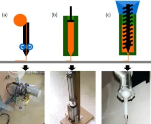
-The tests of a functional prototype set up in a NC. The first work has been done from 2008 to 2011 [4] and has led on a new development with several technologies implemented from 2011 to 2013 (Fig 1).
Fig 1. Overview of technologies implemented: a. Fused depositing; b. Piston depositing; c. Screw
depositing.
II. C
ONTEXT OF ADDITIVE MANUFACTURING The first method to create a three-dimensional object layer by layer using computer-aided design (CAD) was rapid prototyping, developed in the 1980’s to produce models and prototype parts. Additive manufacturing provides fast, cost-efficient production, reduced material usage, and shortens design cycles. This technology was created to help and support the engineers in their conceptualization. Among the major advances that this process presented to product development are the time and cost reduction, human interaction, and consequently the product development cycle [1]. It also provides the possibility to create almost any shape to validate functionality and aestheticism. Those shapes could indeed be very difficult to manufacture with otherprocesses (ex. milling, molding…). Nowadays, these technologies have other names such as 3D printing or rapid manufacturing, and so forth, but they all have the same origins from rapid prototyping. The complex geometries which need a maintaining use a support material. This material can maintain the external and internal surfaces of a part. In most cases, the support material is cleaned during the finishing or trapped into the model. The cost of consumables is often expensive and the loss of material is not considered. Environment impact is not negligible for materials made from resin and it is not compatible with the sustainable approach. Today, we find some wood threads in Fused Depositing Modeling (FDM) technologies that are composed of recycled wood and polymer used as binder. It provides objects having the “appearance” and the smell of wood1. This work is distinguished
by the use of biodegradable materials without synthetic polymer.
III.
I
SSUES AND RESEARCH OBJECTIVEThe research work presented in this paper is built around several observations. The rapid prototyping machines are often sold in a complete unit. The second observation is based on size prototype feasibility: manufacturing dimensions are limited. The last observation is the use of non-renewable materials which have an environmental impact. That led the authors’ interest to use bio-based material like wood. The paper presents the achievement of a prototyping device answering these constraints with a functional prototype and associated software.
IV. C
ONTEXT OFE
CO-D
ESIGN APPROACH Wood is a biodegradable organic material which is more or less long term reinstated in the natural carbon cycle [10]. The wood leads to the carbon-dioxide reduction emissions to a non-renewable materials alternative. The latter leading to energy costs and negative impacts that are hard to be sustained by our ecosystem. The wood life cycle includes some compounds that involve all materials using wood material processed as main base, such as plywood, particle board, fiber, etc. Any material that has little value which can be recycled is collected, crushed, shredded, fiberized, and may result in reconditioned wood material like the wood flour, with or without the addition of binder to give paper, cardboard, fiberboard or particles [6]. Their techno-economic value offers significant opportunities for industry sectors of construction, layout, and furniture incorporating recognized decorative technics. The wood appearance and its aesthetics are undoubtedly an advantage for this material. Its use in wood1 www.makerbot.com
derivatives shows that other applications are possible without translating the aesthetic and structural advantages of wood.
With the wood flour integration as main element in a process, it would be possible to obtain a homogeneous and isotropic material, unlike solid wood. Its high sensitivity to humidity forced to limit the use of such material. In order to realize wood pulp suitable for the additive deposition, we lead an experiment to achieve it.
V.
D
ESIGN OF EXPERIMENTS FOR WOOD PULP ACHIEVEMENTThe Design Of Experiments (DOE) method can both reduce the number of tests, and study a large number of factors, but also detect possible interactions between factors. The study of one factor at a given level is done by comparing the average responses obtained at this level to the overall average [8]. According to the definition of full factorial, one has an answer for each combination. Authors choose to apply the DOE method in order to discover the effects of the process and of the chosen material on various predefined geometrical shapes.
1. NATURAL MATERIAL USED
The literature search has identified influential factors such as high sensitivity of the materials to moisture (wood and starch).In their experiments, authors use beech flour with two different grain sizes detailed in Table 1: LIGNOCEL HB 120 and ARBOCEL HW 630.
Table 1. Beech flours
We also use a modified starch as binder (Table 2). The chemically modified starches develop their viscosity and their binding property at low temperature or at normal cooking temperatures in environments where water availability is limited. This category gathers those modified starches obtained by reaction of hydroxyl groups of starch with monofunctional agents to introduce substitution groups. The purpose of treatment is to stabilize the amylose against the retrogradation and prevent the intermolecular association of amylopectin fractions. The ester introduction or ether groups into the starch molecule can stabilize the viscosity, especially at low temperatures [1]. Note that starch is sensitive to humidity and its mechanical properties decrease with increasing moisture. The introduction of new hydroxylated functions provides a moisture level equivalent or superior to that of native starch. The chemicals are no longer present in the final modified product, it is completely biodegradable. However, it should be noted that the natural character of the starch decreases with increasing
etherification.
Table 2. Modified starch
The objectives are assess the various factors that make pulp from its mechanical behaviour and rheological criteria.
Consequently, the studies are made on parameters that have a significant influence, namely:
- The grain sizes of beech flour: 40 µm and 120 µm
- The mass of beech flour: 20 g and 40 g - The mass of ether starch: 10 g and 40 g - The volume of demineralised water: 200 ml
and 300 ml
2. EXPERIMENTATION CONDITIONS
First of all, we produced the test manually without NC machine. Technically the thread filing is feasible, but the first resources do not permit to automate the descent of the plunger. Nevertheless, authors assume the independency of that issue on the results. We use normalized tensile specimen realized by dough depositing in order to characterize the material. Manufacturing parameters of specimens are:
- Thread diameter: 2 mm - Temperature: 20 ° C - Humidity: 55% RH
- Material: Beech flour 20 µm and 120 µm (deciduous)
The tensile strength measurement is performed on a strain-compression machine with a sensor 100 daN. The deformation is measured on the initial length (L0%); the measure of stress is MPa. The tests are conducted in an environment at a temperature and humidity of 42% RH.
Authors did not have tools to directly measure the rheology of the pulp. Authors then applied the criteria of observations to assess the wire held: Good behaviour: criterion n° 1; Medium behaviour: criterion n° 2; Worse behaviour: criterion n° 3.
3. PRACTICAL METHOD
Authors use a two-level plan, with the study of all the possible bilateral interactions per sample type, which corresponds to an L 16 table. The chosen levels chosen are shown in table 3. The conditions were chosen on both sides of the test conditions of reference presented in the preceding paragraph.
The DOE construction is shown in table 4. The specified outcomes are the measurements averages of performed in tension on a family of three identical specimens. To summarize, authors have three outcomes: the maximum strain in MPa named A, the elasticity modulus in MPa, named B and the rheological criteria assessed during the extrusion performed with a syringe, named C.
Table 4. DOE construction and results
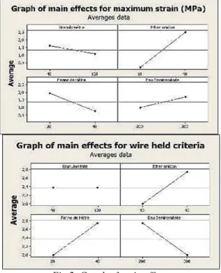
We can study the graphs of main effects to analyse the factors. The slope importance on each parameter gives information on the importance of the influence of this parameter. More the factor effect is important; more the segment slope is strong. Therefore, it was a means of quick visual assessment on the same graph to analyse the relative influence of representative factors detailed in Figure 2. We observe that the modified starch influences the wood pulp tensile strength.
Fig 2. Graph of main effects
An interaction between factors occurs when the answer modification obtained on minimum level or on maximum level of a factor differs from the modification of the response on two identical levels of a second factor. In other words, the factor effect depends on another factor. You can use interaction diagrams to compare the relative strength of the different factors effects (it is not the purpose of this article).
4. OPTIMIZATION
The desired response optimized sought is a combination of input variables that jointly optimizes a set of answers while satisfying the required conditions for each response of the set [16]. To optimize the manufacturing conditions of forms, individual desirability are defined for each response. Therefore, we must increase our desire to obtain the best possible thread place during manufacture while maintaining a tensile high stress. We keep the goals while maximizing the responses. The optimization diagram illustrates the effect of each factor on the responses or composite desirability. For the individual desirability authors select a weight (between 0.1 and 10) to define the importance of the reaching of the target value. The composite desirability is the weighted geometric mean of individual desirability of different answers. Table 5 summarizes the results and "best" configuration to simultaneously maximize the outcomes.
Table 5. Optimization responses
In this study, the composite desirability (0.86) is fairly close to 1, indicating that the settings seem to achieve favourable results for good performances of the thread during the manufacturing and it responds to using features.
5. CONCLUSION
In this section, authors exploited solutions by depositing a wood pulp thread. They proposed a method applied on a NC machine. Then, they propose the experimental method which allows wood pulping to answer manufacturing constraints. The proposed approach manages the professional rules specific to the process. Modified starch used is the most important factor affecting the tensile strength of the material. The flour beech fibre size may affect the resistance in our setup, contrary to what authors thought. The starch needs enough water and does not need a high load of flour to achieve its characteristics.
To maintain the thread filing, it is more stable when the pulp is made up of less water and more flour. Starch is undeniably the invariant factor in our
composition. The study shows that the beech flour and starch interactions have a strong responsibility to hold the thread in the presence of demineralised water. With the aim to improve our wood pulp, authors headed towards the responses optimization to be closer to the best terms of use and manufacture to realize the first wood model in deposition modelling (Fig 3.).
Fig 3. First reconstituted wood model by additive manufacturing
In addition, the aesthetics should be improved to touch the expected general public. Opportunities for improvement are possible, such as reducing the diameter of the nozzle which requires a mechanization of the piston and the establishment of a chemical research phase deeper on the composition of the pulp.
VI.
3D
PRINTING APPLICATIONS OF WOOD MODELSIn this section, we give an overview of two ways used to assess the scientific and technologic problems. After describing some approaches and methods, we tried to integrate wood in the form of powder (wood flour, wood powder).
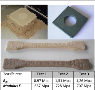
A first complementary experiment was to test the beech flour through a binder projection machine with a ZCorp 3D printer (fig 4). A post-treatment was considered by dipping a form in industrial wax to increase our required forms (we also tested a natural wax). Without immersing the piece in the molten wax bath, we introduced the model in surface. The wax rises up by capillary action. The part was intact on the top surface, but its base is degraded by the soaking support. It can be manually manipulated after solidification. We have realized different mechanical tests to obtain the wood model behaviors through specimens [5]. Each geometrical model has its specificities as measure of dimensional stability (flatness, circularity ...) or mechanical strength.
Tensile test Test 1 Test 2 Test 3
Rm 0,97 Mpa 1,51 Mpa 1,26 Mpa
Modulus E 667 Mpa 728 Mpa 707 Mpa
Fig 4. Wood flour experimentation and its wax treatment. Specimen output printer and post-treatment specimen. Summarize tensile tests.
We can observe the elastic modulus and the rupture limit of the specimens. Also results can be dispersed and give us insight into the behaviour of the material in tension. Its tensile strength is low (between 0.97 MPa and 1.51 MPA), but sufficient for some consumer products (ex: figure 5). We wanted to present the first application to show that we have looked for other wood shaping solutions.
The second experimentation used a syringe to deposit wood pulp based on wood flour and starch (fig 5). A Design Of Experiment (DOE) has been implementing to reduce the number of tests, and study a large number of factors, but also to detect possible interactions between factors [3]. We optimized the composition of the material through a parameter design optimization [5, 16]. This syringe has been adapting on a NC machine.
Fig 5. Second syringe experimentation with a wood pulp
We have realized different mechanical tests to obtain the mechanical wood pulp behaviors [5]. The behaviors were used to create a product able to respond to use constraints (§5).
A study case involves applying the search results to a specific model (fig 6. Tape dispenser). We have created the first object in reconstituted wood through an additive manufacturing.
Fig 6. Study case: Tape dispenser
These depositing applications briefly present the first studies before presenting the following work. The connection is very strong between these two stages through the wood studies and possible automation system. In order to work and go further in the process, we have developed an independent print head able to be installed on a NC machine to extrude different pulp.
VII.
D
EVELOPMENT OF3D
PRINTING DEVICE With the assumption that it is possible to develop a print head for any NC machine, three main functions have been studied: the device design and its depositing system, the development of specific software to control the NC machine and the wood deposition manufacturing (Fig 7).Fig 7. Virtual solution of rapid printing head
During our study, we tried several technologies for depositing (fig 1): the fused depositing which is the existing solution, the piston depositing which required an extrusion system, and the screw depositing which used a worm system. We present below the piston depositing system because other systems were less effective.
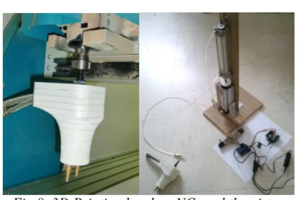
1. 3D PRINTING HEAD FOR NC MACHINING The aim was to automate the previous system and offer an innovative and interchangeable solution, like machining tools. We have developed a printing head (Fig 8) to deposit wood pulp with the requirement to support the model geometry. Indeed, as all additive processes, it must support the complex geometries which require being held. We have designed a head containing two nozzles to prepare this constraint.
Fig 8. 3D Printing head on NC, and the piston depositing.
A prototype has been realized to answer to automation problem and we realized this prototype in extruded polystyrene by a Stratoconception© method2. We have identified a solution which integrates the NC machining spindle instead of the end-mill. This solution has proven its advantages compared to existing solutions:
-It allows the manufacturing of large prototype thanks to the machining table;
-It is useful to assess some other pulps;
-It simply requires changing the machining tool (just the end-mill).
We used an extrusion system which works with a piston and different supply pipes. Nozzles were used to deposit the wood pulp and others dough (fig 9). The nozzle diameters are from 2mm to 0,4mm.
Fig 9. 3D Printing head’s nozzles
We used an electronic card (Arduino®) and a pneumatic switch connected to a compressor to control a pneumatic cylinder (fig 8). We chose a pneumatic solution instead of an electric solution because it was cheaper, but it implies a low reactivity. The pneumatic cylinder was sized to a pressure drop and a minimum flow (cylinder Ø 40mm, cylinder stroke 200 mm, force 80 Newton for a pipe of Ø 4mm and 1 meter long). The piston is provided with a valve and a container for the pulp. The container is connected with the pipe to nozzle’s printing head. To use the second nozzle and integrate a support material, the piston depositing system must be duplicated.
This additive deposition system is linked to a manufacturing process which is defined between the
2
material behaviors and manufacturing parameters. When we combine the use of wood pulp, the piston depositing and the NC machining, all product parameters are linked by the trade rules and constraints. To control the whole, we must combine all the parameters while driving the CNC machining and the pneumatic depositing system through specific software.
2. SPECIFIC ADDITIVE MANUFACTURING SOFTWARE
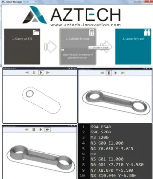
A Computer Numerical Control (CNC) system is automated using computer-aided design (CAD) and computer-aided manufacturing (CAM) programs. The programs produce a computer file that is interpreted to extract the commands needed to operate a particular machine via a post processor, and then loaded into the CNC for machining a model. The goal is not to physically change the machine, beyond the existing the NC machining spindle. So we had to adapt the native control system without using invasive techniques for the NC machining. Dedicated computer software has been developed to generate a G Code understandable by all NC machining, corresponding to the course that the machine must follow to manufacture a model by material deposition. While the NC was able to move the nozzle along its theoretical course, we had to synchronize the pressure applied by the pneumatic cylinder to actually deliver the wood along the given trajectory.
There are freeware solutions as RepRap [12], fab@home [9] or Slic3r software, but they do not allow the simultaneous control of a CNC and an independent extrusion system. We developed software that was able to import geometry (STL, CAD Import). Generating a trajectory for the NC machine needed to take into account the new production process. The CNC is able to follow a path easily to remove material, but using a depositing head, we had to carefully identify a relevant path for additive-based solution (only one pass per point, etc.). We had to find a solution to synchronize the position of the CNC over this path and the pneumatic pressure. This synchronization is held by the spindle speed command of the CNC (code S and M). By measuring the rotation speed, applied through the G code, the Arduino controller is able to read in the desired delivery rate and to adjust the pressure. Testing had to be done to adjust the pressure inertia. The G code production has been adjusted consequently. A visual 3D simulator has been developed to help us check the quality of the path. Full software suite is visible on Fig 10.
All the material behaviors are encapsulated into software controls which provide to the device the
properties necessary to make the manufacture by layers.
For example, the device is capable to work with different materials which can be extruded under pressure from a wire pulling. The proper settings and configurations will be different for each material and processed by the software. They will also vary according to things such as temperature, pressure, humidity, nozzle size, etc. Therefore, the user is self-sufficient and need to determine the proper settings depending on the material.
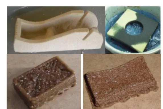
Fig 10. Additive manufacturing software for CNC machining and piston depositing system. 3. REVIEW OF MANUFACTURED WOOD MODELS We formed some geometry after realizing the mechanical characterization. Firstly, the integration of wood powder in 3D printing leads to brittle parts, but are hardened by soaking in a wax. Secondly, we have developed wood pulp based on starch and wood flour for extruding it through a depositing system (fig 11). These two approaches have an advantage and a weakness, the material is sustainable but the involvement of water induces a high shrinkage. Due to hydrophilic materials used. After making several models, we observed some irregularities in their geometries. During the scan of pulp depositing, the changing of tool directions generates protrusions mainly because of bad extrusion control. Nevertheless, the shape of the model corresponds to the initial geometry and the manufacturing process has been effective. Subsequently, internal tensions gradually deform the geometry during the drying.
Fig 11. Review of models produced: wood powder and wood pulp.
To measure these geometrical deformations, we used a three-dimensional measuring machine. The circularity has a decreased high deviation in the range from -0.034 mm to -0.414 mm for the wood powder and wax specimen. The measures show that a hole is not circular and is deformed towards the ends of the model. The planarity is also affected by the cooling of the wax. Tensions deform the corners of few millimeters on both approaches (warping and local ductile distortion).
VIII.
C
ONCLUSION AND FUTURE WORKS The goal of this paper was to show the possibility to integrate a wood flour or wood pulp to produce reconstituted wood product through an additive manufacturing process. We showed that use of wood pulp has an interest to obtain sustainable products. Based on a first application and model examples, we have shown that many parameters, from different components, are important. We have realized mechanical tests to assess the mechanical behaviors of wood pulp through a Design Of Experiment (DOE). The wood pulping is used through different experiments. The research results have led to new applications of additive manufacturing through a piston depositing which require an extrusion system. This piston depositing has got a printing head which is interchangeable on the NC machines instead of machining tools. Obviously, the final reconstituted wood models lack of precision. We still have a lot of work before obtaining a reliable product, but this development suggests a new approach in the pulp depositing with an additive manufacturing functional device. If the STL format allows exporting of a surfacing model towards the specific software, upstream work has to be done in CAD to integrate the rule rules. The emergence of more enriched new exchange format as the Additive Manufacturing File (AMF) process important parameters (<material>, <composite>, <metadata>…) or the STL 2.0. [7] The study shows that we need to transfer more data to the rapid manufacturing.During the study, other materials are identified like the hydraulic materials. The fibers integration and the study of their orientation could improve the mechanical characteristics of reconstituted wood products (fiber strengthening). Due to their low weight and low maintenance, composite materials have an even more important role to play. Our study is directed towards the manufacture of composite structures (which is fundamentally already the case).
IX.
A
CKNOWLEDGEMENTSThis work has been partly funded by: Aztech, OSEO (Bpi France) and Conseil General des Ardennes.
B
IBLIOGRAPHY[1] Banks, W. and Greenwood, C.T. 1975. Starch and its Components. (1975).
[2] Bernard, A. and Fischer, A. 2002. New Trends in Rapid Product Development. CIRP Annals -
Manufacturing Technology. 51, 2 (2002),
635–652.
[3] Condra, L. 2001. Reliability Improvement with
Design of Experiment, Second Edition,. CRC
Press.
[4] Gardan Julien 2011. Application to use of a
wood derivative in rapid prototyping for the emergence of general public product. UTT -
ICD-LASMIS.
[5] Gardan, julien and Roucoules, lionel 2011. Characterization of beech wood pulp towards sustainable rapid prototyping. International
Journal of Rapid Manufacturing (IJRapidM), Inderscience. (2011).
[6] Handbook, W. 1999. Wood as an Engineering Material, United States Department of Agriculture, Forest Service. General Technical Report FPL-GTR-113. 24, (1999).
[7] Hiller, J. and Lipson, H. 2009. STL 2.0: A Proposal for a Universal Multi-Material Additive Manufacturing File Format. Proc.
Solid Freeform Fabrication Symposium (SFF’09), Austin, Texas (2009), 266–278.
[8] Hinkelmann, K. 2011. Design and Analysis of
Experiments, Special Designs and
Applications. John Wiley & Sons.
[9] Malone, E. and Lipson, H. 2007. Fab@Home : the personal desktop fabricator kit.
Mechanical and aerospace Engineering, Cornell University, Rapid Prototyping Journal. Emerald Group Publishing, (2007).
[10] Miller, R.B. 1999. Structure of wood. Wood
handbook : wood as an engineering material.
Madison, WI : USDA Forest service, Forest Products Laboratory, (1999), 2.1–2.4.
[11] Sagot, J.-C., Gouin, V. and Gomes, S. 2003. Ergonomics in product design: safety factor.
[12] Sells, E., Smith, Z., Bailard, S., Bowyer, A. and Olliver, V. 2010. RepRap: The Replicating Rapid Prototyper : Maximizing Customizability by Breeding the Means of Production. Social Science Research Network. (2010).
[13] Skander, A., Roucoules, L. and Klein Meyer, J. 2007. Design and manufacturing interface modelling for manufacturing processes selection and knowledge synthesis in design.
International Journal of Advanced
Manufacturing Technology. (2007).
[14] Wang, H. and Zhang, H.G. 2012. State of the Art in Rapid Prototyping. Advanced Materials
Research. 549, (2012), 1046–1050.
[15] WOHLER, T. 2012. Wohlers Report 2012.
Wohlers Associates. Inc.
[16] Wu C.J., Hamada M.S. 2009. Experiments :
Planning, Analysis, And Parameter Design Optimization. Willey.
