Science Arts & Métiers (SAM)
is an open access repository that collects the work of Arts et Métiers Institute of
Technology researchers and makes it freely available over the web where possible.
This is an author-deposited version published in: https://sam.ensam.eu Handle ID: .http://hdl.handle.net/10985/10198
To cite this version :
Farid ABED-MERAIM, Alain COMBESCURE - New prismatic solid-shell element : Assumed strain formulation and hourglass mode analysis - Structural Engineering and Mechanics - Vol. 37, n°2, p.253-256 - 2011
Any correspondence concerning this service should be sent to the repository Administrator : [email protected]
and hourglass mode analysis
Farid Abed-Meraim
1,†, Alain Combescure
21
LEM3, CNRS, Arts et Métiers ParisTech, 57078 Metz Cedex 3, France
2 LaMCoS, UMR CNRS 5259, INSA de Lyon, 69621 Villeurbanne Cedex, France
Keywords: assumed-strain solid–shell SHB6; six-node prism; shear and thickness locking; hourglass.
1. Introduction
In three-dimensional analysis of structural problems, the development of effective eight-node solid-shell finite elements has been a major objective over the last decade (Belytschko and Bindeman 1993, Hauptmann and Schweizerhof 1998, Abed-Meraim and Combescure 2002, Legay and Combescure 2003). However, to be able to mesh complex geometries and with the advent of free mesh generation tools not generating only hexahedrons, the development of prismatic elements is made necessary. This paper presents the formulation of a six-node solid-shell called SHB6. It represents a thick shell obtained from a purely 3D approach. The assumed strain method is adopted together with an in-plane reduced integration scheme with five integration points along the thickness direction. The 3D elastic constitutive law is also modified so that shell-like behavior is intended for the element and in order to alleviate shear and membrane locking.
A detailed eigenvalue analysis of the element stiffness matrix is first carried out. We demonstrate that the kernel of this stiffness matrix only reduces to rigid body movements and hence, in contrast to the eight-node solid-shell element (SHB8PS), the SHB6 element does not require stabilization. On the other hand, to attenuate locking phenomena, several modifications are introduced into the formulation of the SHB6 element following the assumed strain method adopted by Belytschko and Bindeman (1993). Finally, one example, among the variety of benchmark problems performed, is shown to illustrate the performance of the new element.
2. Formulation of the SHB6 finite element
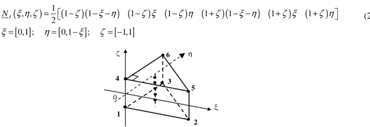
The SHB6 is a solid-shell with only 3 displacement DOF per node, and it has a special direction called “thickness”. It is integrated with five integration points along this direction and only one point in the in-plane directions. Fig. 1 shows the SHB6 reference geometry and its integration points.
2.1 Kinematics and interpolation
The SHB6 is a linear, isoparametric element. Its coordinates x and displacements i u are related to the nodal i
coordinates x and displacements iI u through the linear shape functions iI N as I
∑
= = = 6 1 ) , , ( ) , , ( I I iI I iI i x N x N x ξ ηζ ξ η ζ and∑
= = = 6 1 ) , , ( ) , , ( I I iI I iI i u N u N u ξ ηζ ξ ηζ (1)The standard tri-linear shape functions N are: I
Farid Abed-Meraim and Alain Combescure
(
)
(
)(
) (
) (
) (
)(
) (
) (
)
[ ]
[
]
[ ]
1 , , 1 1 1 1 1 1 1 1 2 0,1 ; 0,1 ; 1,1 I N ξ η ζ ζ ξ η ζ ξ ζ η ζ ξ η ζ ξ ζ η ξ η ξ ζ = − − − − − + − − + + = = − = − (2)Fig. 1 Reference geometry of the SHB6 element and location of its integration points
2.2 Discrete gradient operator
Using some mathematical derivations, similarly to the SHB8PS formulation (Abed-Meraim and Combescure 2002), we can explicitly relate the strain field to the nodal displacements as
( )
, , , , , , , , , , , , , , , , , , 0 0 0 0 0 0 0 0 0 T T x x x x T T y y y y T T x z z z z s T T T T x y y x y x y x T T T T x z z x z z x x y z z y T T T T z z y y b h u b h u d b h u u d u u b h b h u u b h b h u u b h b h α α α α α α α α α α α α α α α α α α γ γ γ γ γ γ γ γ γ + + + ∇ = = ⋅ + + + + + + + + +
y z B d d = ⋅
(3)where functions hα are: h1=ηζ, h2 =ξζ; vectors b are: i ,
0 (0) ; 1, 2, 3 T i i i b N N xξ η ζ i = = = = = ∂ ∂ = and the constant vectors α
γ are given by:
(
)
3 1 1, 2 1 ; 2 T i i i hα hα x b α α γ = = =
− ⋅
∑
. In this latter expression,(
)
1 0, 0, 1, 0, 0, 1 ;
T
h = − hT2 =
(
0, −1, 0, 0, 1, 0)
and vectors xi denote the nodalcoordinates.
2.3 Variational principle
Applying the simplified form of the Hu-Washizu nonlinear mixed variational principle, in which the assumed stress field is chosen to be orthogonal to the difference between the symmetric part of the displacement gradient and the assumed strain field, we obtain:
( )
, 0 e T T ext V u dV d f δπ ε =∫
δ ε σ⋅ −δ ⋅ = (4)Replacing the assumed strain field, with its expression ε
( )
x t, =B x( ) ( )
⋅d t , in Eq. (4) leads to the following expressions for the element internal force vector and stiffness matrix:( )
int e T V f =∫
B ⋅σ ε dV, T e e V B C BK
=
∫
⋅ ⋅dV
(5) 0 ζ η ξ 4 3 5 1 2 6For a standard displacement approach,
B
is simply replaced byB
leading classically to e T e VK
=
∫
B
⋅ ⋅
C B dV
(6)2.4 Hourglass mode analysis for the SHB6 element
Hourglass patterns are spurious zero-energy modes that are induced by reduced integration. The analysis of hourglass modes is equivalent to that of the stiffness matrix kernel, namely searching for zero-strain modes d that satisfy:
( )
I 0B ζ ⋅ =d , I =1, ...,nint (7)
where nint represents the number of integration points.
To this end, we can build a basis for the vector space of the discretized displacements, given by the eighteen column vectors below, in which ST =
(
1, 1, 1, 1, 1, 1)
. We show then that only the first six column vectors in Eq. (8) verify Eq. (7), which corresponds to rigid body modes. This reveals that there are no hourglass modes for the SHB6 element, and thus no hourglass control is required. − − − 2 1 2 1 2 1 0 0 0 0 0 0 0 0 0 0 0 0 0 0 0 0 0 0 0 0 0 0 0 0 0 0 0 0 0 0 h h y x z y x S h h z x y z x S h h z y x z y S (8)
2.5 Assumed strain formulation for the SHB6 discrete gradient operator
Among several treatments for alleviating shear and membrane locking, in the present formulation the discrete gradient will be appropriately modified. This consists first of decomposing the matrix
B
into two parts:2
1 B
B
B= + , then of projecting the second part onto an assumed strain operator such that
1 2
B =B +B . As a
result, the stiffness matrix becomes
1 1 1 2 2 1 2 2
e e e e
T T T T
e V V V V
K
=
∫
B
⋅ ⋅
C B dV
+
∫
B
⋅ ⋅
C B dV
+
∫
B
⋅ ⋅
C B dV
+
∫
B
⋅ ⋅
C B dV
(9)The subsequent steps consist of choosing an adequate assumed strain field. This is a key point in the formulation and special care has been exercised in this regard. Finally, the above additive decomposition of the stiffness matrix is computed using a reduced integration scheme with five Gauss points, all located along the thickness direction. Note that the choice of an assumed strain field is mainly guided by the elimination of strain components that are responsible for shear and membrane locking. The effectiveness of this assumed strain is assessed through benchmark problems.
, , , 1 2 , , , , , , 0 0 0 0 0 0 0 0 0 0 0 0 0 0 0 ; 0 0 0 0 0 0 0 0 0 0 0 0 T T x x T T y y T T z z T T T T T T T T y y x x z z x x T T T T z z y y b h b h b h B B b h b h b h b h b h b h α α α α α α α α α α α α α α α α α α γ γ γ γ γ γ γ γ γ + + + = = + + + + + +
Farid Abed-Meraim and Alain Combescure
3. Numerical results and comparison
Several popular benchmark problems were performed to illustrate the element performance. One of these test problems, which is frequently used to test warping effects, is shown here.
E = 29×106 ν= 0.22 P= 1 L= 12 l= 1.1 h= 0.32
Fig. 2 Twisted beam (reference vertical displacement of point A at tip is 5.424x10⁻³) Table 1 Normalized vertical displacement at point A of the twisted cantilever beam problem
Mesh layout PRI6 (3D solid element) SHB6 (without assumed strain) SHB6 (assumed strain)
(6x2x1)x2 0.061 0.234 0.496
(12x4x1)x2 0.202 0.470 0.784
(24x4x1)x2 0.485 0.779 0.935
(36x8x1)x2 0.489 0.875 0.972
4. Conclusions
This newly developed SHB6 element was implemented into the finite element codes INCA and ASTER. It represents some improvement since it converges well and it performs much better than the PRI6 six-node three-dimensional element in all of the benchmark problems tested. Furthermore, it shows very good performances in problems using mixed meshes composed of SHB6 and SHB8PS elements. Thus, we can couple the SHB6 with other finite elements to mesh complex geometries, which could be obtained by free mesh generation tools.
References
Abed-Meraim, F. and Combescure, A. (2002), “SHB8PS a new adaptive, assumed-strain continuum mechanics shell element for impact analysis”, Comput. Struct., 80, 791-803.
Belytschko, T. and Bindeman, L.P. (1993), “Assumed strain stabilization of the eight node hexahedral element”,
Comput. Meth. Appl. Mech. Eng., 105, 225-260.
Hauptmann, R. and Schweizerhof, K. (1998), “A systematic development of solid-shell element formulations for linear and non-linear analyses employing only displacement degrees of freedom”, Int. J. Num. Meth. Eng., 42, 49-69.
Legay, A. and Combescure, A. (2003), “Elastoplastic stability analysis of shells using the physically stabilized finite element SHB8PS”, Int. J. Num. Meth. Eng., 57, 1299-1322.