Publié dans: The Fifth International Conference on Sustainable Construction Materials and Technologies (SCMT5), Kingston University London (UK), 15–17 July 2019, paper SCMT5046
SHEAR STRENGTHENING OF THICK CONCRETE SLABS ACCOUNTING FOR LOADING DURING STRENGTHENING
Bédard, Frédéric1; Fiset, Mathieu2; Bastien, Josée3; Mitchell, Denis4;
11065 Avenue de la Médecine, Québec, QC G1V 0A6, frederic.bedard.5@ulaval.ca, Université Laval
21065 Avenue de la Médecine, Québec, QC G1V 0A6, mathieu.fiset.1@ulaval.ca, Université Laval
31065 Avenue de la Médecine, Québec, QC G1V 0A6, josee.bastien@gci.ulaval..ca, Université Laval
4817 Sherbrooke Street West, Montreal, Quebec H3A 0C3, denis.mitchell@mcgill.ca, McGill University
ABSTRACT
In order to investigate the effect of the service shear load at the time of strengthening a thick slab using bonded transverse reinforcing bars, an experimental study has been carried out. Five (5) beams representing slices of a thick slab were tested to induce different shear load levels in the beams at the time of strengthening then loaded up to shear failure. Tests were conducted on a slab without shear reinforcement and the others on slabs strengthened at two different load levels at the time of strengthening. The added shear reinforcement was distributed according to two different longitudinal spacings. The results show that, even in the presence of usual service loads, the shear strengthening of thick slabs with bonded bars offers a considerable increase in shear capacity compared to a thick slab without shear reinforcement.
Keywords: Existing thick concrete slab, service load, shear strengthening, epoxy adhesive, post-installed bonded reinforcement, experimental tests
1. INTRODUCTION
There are many examples of aging existing structures suffering from deterioration of the materials and hence may no longer offer a sufficient margin of safety to withstand present or future loads. The reconstruction of these structures may then seem a likely solution. The choice of such an option results in a large volume of demolition waste and requires the production of a considerable quantity of new material for the new construction. The environmental footprint of such a structural improvement becomes onerous. However, the strengthening of an existing structure makes it possible to extend the lifespan while keeping the materials in place and adding a small amount of new materials.
2 Proper functioning of civil infrastructure is vital for society as it sustains services such as transportation, communication or power production. Many of these older structures have suffered deterioration and detailed evaluations may lead to the conclusion that they are no longer safe. The strengthening of a structure may be executed over a shorter period of time and more locally on a structure compared to complete replacement. The strengthening option of maintaining civil engineering structures results in less negative impact on the provision of essential services for citizens.
2. SHEAR STRENGTHENING OF THICK CONCRETE SLABS
A significant number of short and medium span bridges consist of reinforced concrete thick slabs without shear reinforcement. Traffic loads induce a variety of stresses in the slab, such as one-way shear, which is the main subject of this research project. Shear may cause the collapse of the structure through the formation of a major diagonal crack over the depth of the member (see Figure 1). In a thick slab without shear reinforcement, the shear is resisted by the concrete. The shear capacity is governed by the tensile resistance of the diagonally cracked concrete and the ability of the concrete to resist shear along the diagonal crack interfaces. (Collins et al., 1996 and 2008). However, due to concrete degradation over time, poor construction or repair, or increasing loads, many older structures are deficient in shear.
Figure 1. Shear failure in a thick concrete member (Mitchell et al., 2011)
Another key aspect is that thicker members fail in shear at a smaller shear stress than thinner members due to the “size effect”. This phenomenon was not addressed in older codes and therefore many older slab bridges without shear reinforcement may be deficient in shear even without deterioration of the materials. When structural analysis reveals that a member has insufficient shear capacity, shear strengthening is required. The insertion of transverse bars in drilled holes and anchored with epoxy adhesive proves to be an advantageous strengthening solution, since these reinforcing bars serve as stirrups. This strengthening technique is especially suitable for thick slabs since the bonded bars can be distributed uniformly within these wide elements, both in the longitudinal and transversal directions. In the last decade, experimental and analytical studies on shear strengthening by insertion of bonded bars in concrete slabs have significantly improved the understanding of the mechanisms between bonded reinforcing bars and the surrounding concrete in resisting shear (Valerio, 2009; Provencher, 2011; Cusson, 2012).
3 It was demonstrated that the performance of a slab without transverse reinforcement can be greatly improved with this practical technique.
The shear strengthening technique studied in this project consists of inserting transverse reinforcing bars into previously drilled holes filled with injected epoxy adhesive. More specifically, the installation steps consist of:
⦁ Drilling holes in the slab (Figure 2a);
⦁ Cleaning the holes according to the recommended procedures (Figure 2b); ⦁ Injecting the epoxy adhesive (Figure 2c);
⦁ Inserting the shear reinforcing bars (Figure 2d).
Figure 2. Shear strengthening with epoxy-bonded reinforcement bars: a) Drilling holes in the slab; b) Cleaning holes; c) Adhesive injection; d) Shear reinforcing bar insertion.
The advantages of this strengthening technique are:
⦁ The entire strengthening operation is practical, being carried out from the top surface of the slab. This simplification considerably reduces the duration and overall cost of the work;
⦁ The inserted bars are completely encapsulated in the slab. There is no protrusion on either the top or bottom surfaces of the slab. This keeps the clearance under the slab and allows for the installation of a waterproofing membrane on top of the slab.
⦁ With a sufficiently small longitudinal spacing between the rows of bonded transverse reinforcement, the strengthened slab behaves similarly to a slab built with conventional stirrups installed during the construction of the slab. Adequate anchoring of the bonded bars allows them to withstand their full capacity when a shear crack opens.
⦁ The shear strength of a strengthened slab can be increased up to 65% and the deflection up to 300% compared to the same slab without transverse reinforcement (Provencher 2011, Cusson 2012, Fiset et al., 2014).
In the last decade, through laboratory tests on slab samples, the capacity of strengthened slabs with bonded bars was compared to that of slabs with stirrups as well as to slabs without transverse reinforcement (Valerio 2009, Fernández et al 2010, Provencher 2011, Cusson 2012). In addition, the bond behaviour of the adhesive used to anchor the bars was analyzed by Villemure et al. (2015, 2016). For a conventional stirrup, the reinforcement is anchored at its
4 extremities by hooks around longitudinal bars. Therefore, the full capacity of the stirrup is reached, regardless of the position of the shear cracking. The performance of bonded shear reinforcement, in turn, depends on the effectiveness of the adhesive to transfer shear between concrete and bonded bars. Thus, the fully effective length is reduced by the length necessary to develop the adhesion of these bars with the concrete. As a result, Fiset et al. (2017) suggests reducing the maximum longitudinal spacing, sv, of the added bonded transverse reinforcement
from the spacing typically used in the design of stirrups. 3. OBJECTIVE
Past research on strengthening of thick slabs using an epoxy adhesive was carried out on members that were not loaded during strengthening. However, an existing thick slab can already be carrying a shear of up to 70% of its shear capacity before the strengthening is carried out. This load is mainly attributable to the weight of the structure and can reduce the effectiveness of added bonded bars as shear reinforcement. It has been shown by Eligehausen (2006) and Villemure (2015) that deformations and cracking of concrete at the moment of strengthening is potentially detrimental to the bond strength of bonded bars. Moreover, the remaining shear capacity can be insufficient to fully develop the capacity of the bonded bars (Fernández et al., 2010). While the slab is already heavily stressed, inserted bars are not yet active (zero stresses). An increase in load and deformation is therefore necessary to develop tensile stresses in the bonded bars. The objective of this research project was to assess the influence of the level of initial loading and deformation present at the time of installation of epoxy-bonded shear reinforcing bars into a thick slab. To achieve this, an experimental investigation was conducted.
4. EXPERIMENTAL INVESTIGATION
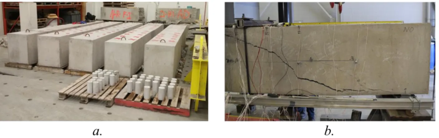
Five beams of realistic scale (610 mm width (bw) x 750 mm height (h) x 4500 mm span (2a))
were built at Université Laval, as shown in Figure 3a. These beam specimens represent thick slab slices. The specimens were subjected to a three-point flexural loading test (Figure 3b). With a shear span to depth ratio (a/d) of 3.3, shear failure was expected.
Figure 3. a) Experimental slab specimens; b) Slab submitted to a three-point flexural loading test
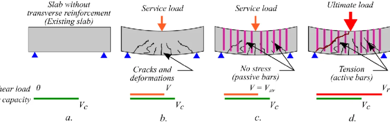
5 One of the slabs was used as a control specimen. This slab did not contain any transverse reinforcement and was loaded up to shear failure to determine the concrete shear capacity, Vc
(Figure 4a). This capacity was used to define the service load at which the shear strengthening was installed in the other slabs. Then, these other four slabs, initially without shear reinforcement, were loaded up to a predetermined shear service load (Figure 4b).When the targeted shear load was reached (Vstr), the slab deflection was maintained and the slabs were
shear strengthened with added bonded bars (Figure 4c). Once the curing of the adhesive was completed (more than 16 hours according to the manufacturer of the adhesive (Hilti, 2017)), the loading was resumed until shear failure occurred (Figure 3b and 4d). Two levels of shear loading at the time of strengthening were studied, 60% and 80% of the shear capacity of the specimen without transverse reinforcement (Vc).
All specimens contained a longitudinal reinforcement ratio Asx/(bwd) of 2.0% installed at an
effective depth (d) of 683 mm. The resulting shear depth, dv = 0.9d, was 615 mm for all
specimens. The concrete properties were similar for all slabs and the average concrete compressive strength (𝑓𝑐′) measured on cylinders at the day of testing the slabs was 39.4 MPa.
The steel bars used as shear reinforcement had a nominal diameter (db) of 15.9 mm, for a total
area of shear reinforcement (Asv) of 400 mm². These steel bars had a Young’s modulus (Es) of
203 000 MPa and a yielding strength (fy) of 403 MPa. The longitudinal spacing to shear depth
ratios (sv/dv) of 0.61 and 0.67 were selected to respect the limits suggested by Fiset et al. (2017)
for added bonded bars. The epoxy adhesive used to bond the post-installed shear reinforcement had, according to the manufacturer, a bond strength, tensile strength and modulus of 10.8 MPa, 49.3 MPa and 1493 MPa, respectively (Hilti, 2017).
Figure 4. a) Slab without transverse reinforcement; b) Slab without transverse reinforcement subjected to service load; c) Strengthened slab at service load; d) Strengthened slab at ultimate
load and shear failure
5. EXPERIMENTAL RESULTS
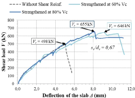
Figure 5 shows the shear versus deflection curves of three experimental slabs: one without shear reinforcement and two with added bonded shear reinforcement (sv / dv = 0.67), each strengthened
at different initial load levels (Vstr) of 60% and 80% of Vc. The spacing of the added reinforcing
bars is sv and dv is the effective shear depth taken as 0.9 times the effective depth, d. It can be
seen that the maximum shear load carried out by the strengthened slabs is approximately 150 kN greater than the one carried by the slab without shear reinforcement, even if the slab was strengthened under significant service loads. It can also be seen in Figure 5 that the shear
6 capacities, Vr, of 646 kN and 655 kN for both strengthened slabs are similar, even if the shear
load Vstr/Vc at the time of strengthening is 20% higher in the latter.
Figure 5. Shear-deflection response of a slab without shear reinforcement and two slabs with added transverse bars strengthened at 60% and 80% of their unreinforced shear capacity, Vc
(sv/dv = 0.67 for both reinforced slabs)
Figure 6 shows the increase in shear capacity obtained experimentally in the slabs strengthened under load compared to a slab without shear reinforcement. Results are shown for the two different spacings and the different initial load levels studied. For comparison, a similar slab with bonded shear reinforcement installed before loading (Vstr = 0 kN) and tested by Cusson (2012) is
presented in the figure. As it can be seen that, even under a shear at the time of strengthening (Vstr) up to 80% of Vc, the shear strengthening results in a large increase in shear capacity for
both sv / dv ratios. For a sv/dv ratio of 0.67, the capacity increase is almost 30%. For sv/dv = 0.61, the increase in capacity is even more considerable, reaching 62% to 76% more than that of a slab without shear reinforcement. The slabs with smaller values for sv/dv resulted in higher strengths as expected since the transverse reinforcement is closer together. Moreover, it can be seen from the results of Cusson (2012) in Figure 6 that for the same sv/dv ratio of 0.61, a slab that is strengthened without an initial shear loading (Vstr = 0) experiences a similar increase in shear
capacity than the slabs strengthened under shear loads. Overall, no apparent reduction of the shear capacity for the strengthened slabs due to the service load at the time of strengthening was observed up to Vstr/Vc = 80%.
7
Figure 6. Increase in shear capacity of shear strengthened slabs (Vr/Vc) for two spacing ratios (sv/dv) and for different initial shear loads (Vstr/Vc) at the time of strengthening
6. CONCLUSION
This project investigated the effect of the service shear load level, at the time of installation of bonded bars, on the shear capacity of thick slabs. Slabs strengthened while resisting service loads representing 60% and 80% of their capacity before shear strengthening were tested up to shear failure. The results of this study show that the shear reinforcement technique largely increases shear capacity of all slabs, up to 76% larger than a slab without shear reinforcement. It was found that installing bonded shear reinforcement at a service loads up to 80% of the capacity of the slab before strengthening does not significantly reduce the shear capacity. Based on the parameters studied in this project, it is concluded that the use of added epoxy-bonded bars provides a practical method for achieving adequate shear strengthening.
7. ACKNOWLEDGEMENTS
The authors acknowledge the financial support from the Natural Sciences and Engineering Research Council of Canada as well as the support of the Research Center for Concrete Infrastructure (CRIB). The authors would also like to acknowledge and thank all the CRIB personnel, professionals and students involved in the many facets of this project.
8 8. REFERENCES
Cusson, B. (2012). Renforcement des dalles épaisses en cisaillement. (M.Sc. Thesis). Québec: Université Laval, Canada.
Collins, M.P., Mitchell, D., Adebar, P. & Vecchio, F.J. (1996). “A General Shear Design Method”, ACI Structural Journal, 93(1), pp. 36-45.
Collins, M. P., Bentz, E. C., & Sherwood, E. G. (2008). "Where is Shear Reinforcement Required? Review of Research Results and Design Procedures. " ACI Structural Journal, 105(5), pp. 590-600.
Eligehausen, R., Cook, R. A., & Appl, J. (2006). Behavior and Design of Adhesive Bonded Anchors. ACI Structural Journal, 103(6), pp. 822-831.
Fernández Ruiz, M., Muttoni, A., & Kunz, J. (2010). Strengthening of flat slabs against punching in shear using post-installed shear reinforcement. ACI Structural Journal, 107(4), pp. 434-442.
Fiset, M., Bastien, J., & Mitchell, D. (2014). "Experimental and Analytical Studies of Strengthening using Drilled-in Bonded Reinforcement." European Bridge Conference -
15th International Conference, (p. 12).
Fiset, M., Bastien, J., & Mitchell, D. (2017). "Methods for Shear Strengthening of Thick Concrete Slabs." ASCE Journal of performance and constructed facilities, 31(3).
Hilti inc. (2017). "HIT-RE 500 V3 Epoxy Adhesive Anchoring System", North American
Product Technical Guide, Volume 2: Anchor Fastening, Edition 17. Plano, TX. pp.
138-208.
Mitchell, D., Marchand, J., Croteau, P., & Cook, W. D. (2011). "Concorde Overpass Collapse: Structural Aspects." ASCE Journal of performance and constructed facilities, 25(6), pp. 545-553.
Provencher, P. (2011). Renforcement des dalles épaisses en cisaillement. (M.Sc. Thesis). Québec: Université Laval, Canada.
Valerio, P. (2009). Realistic shear assessment and novel strengthening of existing concrete
bridges. (Ph.D. Thesis), Bath: University of Bath, United Kingdom.
Villemure, F.-A., Fiset, M., Bastien, J., Mitchell, D., & Fournier, B. (2015). "Effet de la réaction alcali-silice (RAS) sur l'adhérence des ancrages époxydiques de barres d'armature." 16e
édition des Journées scientifiques du Regroupement francophone pour la recherche et la formation sur le béton (RF)2B, (p. 9).
Villemure, F.-A., Fiset, M., Bastien, J., Mitchell, D., Fournier, B., & Bissonnette, B. (2016). "Study of Bond between Epoxy, Steel Reinforcing Bars and Concrete Affected by Alkali-Silica Reaction." 15th International Conference on Alkali-Aggregate Reaction, (p. 10). Sao Paulo.