HAL Id: hal-01183811
https://hal.archives-ouvertes.fr/hal-01183811
Submitted on 11 Aug 2015
HAL is a multi-disciplinary open access
archive for the deposit and dissemination of
sci-entific research documents, whether they are
pub-lished or not. The documents may come from
teaching and research institutions in France or
abroad, or from public or private research centers.
L’archive ouverte pluridisciplinaire HAL, est
destinée au dépôt et à la diffusion de documents
scientifiques de niveau recherche, publiés ou non,
émanant des établissements d’enseignement et de
recherche français ou étrangers, des laboratoires
publics ou privés.
Effect of Splitting Factor on Multicast Trees in Optical
Networks
Shadi Jawhar, Bernard Cousin, Samer Lahoud
To cite this version:
Shadi Jawhar, Bernard Cousin, Samer Lahoud. Effect of Splitting Factor on Multicast Trees in Optical
Networks. International Conference on Network Communication and Computer (ICNCC 2011), Mar
2011, New Delhi, India. �hal-01183811�
Effect of Splitting Factor on Multicast Trees in
Optical Networks
Shadi Jawhar, Bernard Cousin, Samer Lahoud
IRISA laboratory, University of Rennes 1, Campus universitaire de Beaulieu, 35042, France
[email protected]
Abstract: Enhanced optical switches structure can now handle
multicast routing in the optical layer. For an optical node to be able to do branching in the physical layer, it must be equipped with a light splitter. Light splitters are expensive equipment. A lot of work had been done in order to reduce the cost of implementing splitters within the network. Moreover, the internal structure of a splitter is enhanced to reduce its cost, and the power loss resulted of multiple splitting. Efficient placement of splitters in the network leads to a reduction in the cost of the network design, and the cost of the generated trees. The splitting capability of each splitter plays an important role on how much branching can be done on the optical node. Also, the splitting capability affects the power loss done on each branching node, and consequently the final power received by each member. This paper studies the effect of the splitting factor on the cost of the generated trees and the value of the power received by each of the multicast group members.
I. INTRODUCTION
Because of its design, an optical cross connect OXC can switch an incoming optical signal to one output interface. The output light wave can have the same wavelength as the input, or can be mapped to another wavelength. In order for the OXC to generate multiple copies of the incoming input, and forward each on different interface, it must be equipped with light splitters. Because of the high cost of an optical splitter, a limited number of optical nodes will have this splitting capability.
Advanced studies [1] [2] show that less than half of the network nodes must be equipped with splitters in order to have a compromise between the multicast routing efficiency and the cost of the nodes with optical splitters. Other studies [3] [4] propose enhanced splitting architectures in order to reduce the cost of an individual multicast capable cross connect MC-OXC. Some of these proposals modify the architecture of the Split and Delivery SaD component. Integrating configurable power splitters [5] inside the SaD component leads to a better performance in terms of the power loss, and in terms of the total cost of the switch itself.
This paper studies the effect of the splitting factor in each multicast capable node on the generated trees. This is done by comparing the splitting capability and the number of splitters distributed in the network. This study is done in terms of the cost of the generated trees on the one hand, and
the reduction of power done on each splitting node on the other hand.
This paper is organized as follows: in section II, a brief description of the architecture of a multicast capable node is presented. In section III, related work on how to enhance the structure of those splitters to reduce the cost, and increase the network performance. Also their placement in the network is presented. In section IV, a comparison between splitting capabilities versus number of splitters is done. In the last section, network performance is evaluated, and results of the evaluation show that reducing the splitting capability and increasing the number of splitters enhance the multicast routing from one side, and reduce the numbers of amplifiers needed from the other side.
II. MULTICAST CAPABLE OPTICAL CROSS CONNECT
An all-optical network is composed of Optical Cross Connects OXCs. An OXC is designed to switch an optical signal from an input port to an output port. This switching can conserve the wavelength or map one wavelength to another. For the OXC to be able to do the multicasting in the optical layer, it must be equipped with an optical light splitter.
The SaD switch structure is shown in Figure 1 with all the required components.
Figure 1 – Splitter-and-Delivery SaD switch
As shown in Figure 1, a P×P Splitter-and-Delivery SaD switch, which consists of P power splitters, P×P optical gates, and P×P photonic switching elements can be used. This
reduces the cost and crosstalk on the one hand, and improves power efficiency on the other hand,
We assume that the splitters are configured to split an input signal into m outputs, 1<m<P (If m = 1, then there is no splitting. If m=P, then it is a broadcast splitting). By configuring the corresponding m 2×1 photonic switches, each of the m resulting signals can be switched to the desired outputs.
III. RELATED WORK
In order to realize all-optical multicast switching, the light trees concept was proposed in [6]. A light path consists of an all-optical channel, which may be used to carry circuit-switched traffic, and it may span multiple fiber links. In order to generate a light tree, splitting must happen in the optical layer.
The main role of an all-optical MC OXC is to split the input signal into multiple outputs without the need of understanding the optical features of the input signal. Therefore, it is composed of multiple passive light splitters. A split operation reduces the power of each of the split signals. Ideally, the power of each output is the (1/m)-th part of the input signal.
The SaD switch was proposed to be the main component of the MC-OXC [3]. In order to reduce its cost and to improve power efficiency this architecture was modified in [4].
A configurable SaD switch using configurable splitters was proposed in [5]. Configurable splitters can be controlled in order to split the incoming signal into m outputs (mא{1,..,P}), where m = 1 corresponds to no splitting and m = P to a broadcast operation. After that, outgoing signals are switched to the corresponding output by using a P2 photonic switch matrix.
Relevant propositions for enhancing the internal structure of the MC-OXC multicast have been presented in [3] and [4]. The enhanced structure is designed to reduce the cost of the SaD switches on the one hand, and reduce the power loss resulted of multiple splitting on the other hand. Some of these proposals are based on configuring multiple wavelengths to be exclusive for multicast transmission. Other wavelengths are used only for unicast transmission.
Multiple enhanced architectures for the MC-OXC are proposed employing the SAD switch [3]. The Wavelength Path WP-OXC consists of de-multiplexers (Demux), SAD switches (SaD SW) and multiplexers (Mux). This arrangement is necessitated to ensure that the WP-OXC be strictly non-blocking. The SaD switch renders any input channel switchable to one or more outputs.
Figure 2 Wavelength Path WP-OXC
WP-OXC will turn blocking only if wavelength conversion is involved. Therefore, Vitrual WP-OXCs are constructed in a different way. Other Virtual wavelength path VWP-OXCs consist of splitters, SAD switches, tunable filters (TF), wavelength converters (WC) and multiplexers.
Figure 3 Virtual Wavelength Path VWP-OXC The placement of the light splitters through over the network plays an important role in generating of the multicast trees. To be able to distribute those splitters in an efficient way, the work in [7] explains the parameters to be taken into consideration. Cost of links based on provisioned multicast traffic, plays an important role in indicating which nodes must be multicast capable.
IV. EFFECT OF SPLITTING FACTOR
Given a network topology made up of optical nodes interconnected by optical links. We consider the US IP backbone network as the realistic topology to study. This network consists of a lot of nodes that can play the role of branching when multicast trees are being generated. This leads to the fact that the splitting factor distribution will totally affect the generated trees.
We study the effect of splitting factor on both the cost of the generated trees and the power loss of signals received by group members. We realize that nodes in this network are either connected to 2, 3, 4 or maximum 5 other nodes. Thus,
splitters that need to be placed on this network can be 1x2, 1x3, or 1x4 types.
The related work presented in the previous section shows that the cost of the light splitter is mainly dependent on the cost of the SaD switches integrated inside it. As a result, we study the distribution of splitters in terms of their number versus their splitting factor.
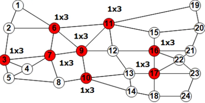
We consider distributing 24 SaD in three different ways. In the first way, we distribute them with maximum splitting capability, which is equal to 4, corresponding to the highest degree, which is 5. Since splitting happens from one input to multiple outputs, then the maximum splitting capability required is 4.
We consider that all the links in the network are identical. We then distribute the splitters on nodes with the highest degree because these nodes are more likely to do branching. As a result, if 6 splitters are to be placed, then these splitters will be placed on nodes 6, 7, 9, 11, 16 and 17. These nodes are the ones with highest number of neighbors. Figure 4 shows the 6 splitters distributed on the nodes with highest node degree.
Figure 4 – Distributing 6 splitters each with 1x4 splitting factor
The 24 SaD switches can be distributed in a different manner, by placing more splitters with less splitting capability. Figures 5 and 6 show respectively how such splitters can be distributed in different procedures.
Figure 5 – Distributing 8 splitters each with 1x3 splitting factor
Figure 6 shows the distribution of the splitters with minimum splitting capability per MC-OXC, which is equal to 2. The maximum these splitters can do is to split one input to two output signals.
Figure 6 – Distributing 12 splitters each with 1x2 splitting factor
Understanding the internal structure of the SaD switch explained in section II, the three schemas have almost the same cost. This is because the number of SaD switches used in each of schema is the same.
We consider that the maximum number of splitters on each node is one. This is because we assume that distributing splitters over a larger number of MCOXC can reduce the blocking ratio, which occurs when multicast incapable cross connect need to do branching.
For reducing the cost of the generated multicast trees and enhancing the performance of each tree, it is highly recommended to place more splitters in the network regardless of their splitting capability. Also, this affects the signal power received by the group members. This power is measured in terms of both the average power received by all members, and the minimum power received by any of the group members.
The advantage of distributing more splitters with less splitting factors is reflected in different points. First, when medium size groups are generated and corresponding multicast trees are constructed, the need for high splitting capability is not essential.
In contrast, the need of more splitters scattered throughout the network is required to generate the spanning trees. The performance and cost of those trees depend more on the number of splitters, rather than the capability of each splitter.
Also, multiple splitting into less number of outputs has less negative effect on the power received by the group members. Constructing trees with branching nodes splitting input to multiple output signals will reduce the power of the signal received by multiple members. This must be resolved by adding more amplifiers with higher gain to conserve the signal from the noise effect. Definitely, this will increase the cost of the network design.
V. SIMULATIONS AND RESULTS
In order to demonstrate that increasing the number of splitters with less splitting capability gives a better performance, simulation is performed. Evaluation is done to compare the effect of the number of splitters versus the splitting capability.
Results are measured in terms of cost of the generated trees and effect on the power of the signal received by group members.
a. Cost of trees and beneficial use of more splitters with less splitting capability
Considering the 24-nodes network topology described in the previous section, we first place 6 splitters with maximum splitting capability, which is equal to 4. This is considered maximum because the highest node degree is 5, meaning that an input signal can be maximum split into 4 outputs. Then, we place 8 splitters each with a splitting capability of 3. Finally, we place 12 splitters each with the minimum splitting capability, which is 2.
We consider 24 x 20 random multicast groups; each time the source is placed on one different node. Group members are then randomly chosen among the network. We vary the size of the group in order to simulate different sizes of groups. As a result, varying the source on all nodes of the network and randomly choosing members and group sizes will give more reliable simulation results.
Each of the three simulated cases, 6 (1x4) splitters, 8 (1x3) splitters, or 12 (1x2) splitters, requires 24 SAD components to be implemented. The difference in the three cases is how these components are distributed.
Then, we calculate the total cost of generating the convenient multicast trees that is capable of performing all optical switching [8] [9]. Since all links are considered identical, the cost of multicast trees is measured in terms of the number of links used to generate the trees.
Multicast trees are generated by applying the shortest path algorithm, to generate the links from the source to the group members. Blocking can occur when a multicast incapable node needs to branch to more than one outgoing link. In this case, it locates an upstream MCOXC to do the branching and generate the multicast tree [10]. In paper [10], multicasting under light splitters constraints is treated to generate the trees in an efficient way, and with the lower cost in terms of used links.
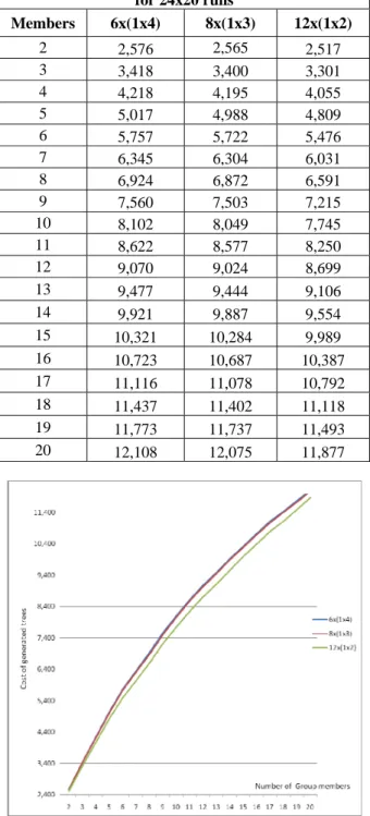
Table 1 shows that using more splitters with less splitting capability reduces effectively the cost of the generated multicast trees. Figure 7 shows graphically the cost of the multicast trees versus the size of the multicast groups.
Table 1: Total number of links of generated trees for 24x20 runs Members 6x(1x4) 8x(1x3) 12x(1x2) 2 2,576 2,565 2,517 3 3,418 3,400 3,301 4 4,218 4,195 4,055 5 5,017 4,988 4,809 6 5,757 5,722 5,476 7 6,345 6,304 6,031 8 6,924 6,872 6,591 9 7,560 7,503 7,215 10 8,102 8,049 7,745 11 8,622 8,577 8,250 12 9,070 9,024 8,699 13 9,477 9,444 9,106 14 9,921 9,887 9,554 15 10,321 10,284 9,989 16 10,723 10,687 10,387 17 11,116 11,078 10,792 18 11,437 11,402 11,118 19 11,773 11,737 11,493 20 12,108 12,075 11,877
Figure 7 Cost of generated trees versus size of groups Figure 8 shows the difference between 6x(1x4) splitter placement and 12x(1x2). It is higher when the size of the multicast groups is medium. This is because when group members are sparsely scattered in the network, the need of more splitters is increased without the need of high splitting factor. This figure shows the cost ? difference versus of the size of the multicast groups.
Figure 8 Difference in trees cost versus size of groups
b. Performance evaluation of the power received by group members, and the need to implement amplifiers.
Splitting factor capability configured in an SAD component has an important influence on the power of each of the branched signals. If a signal is branched to m output signals, then each of the output signals power is 1/m of the input power. This requires the placement of multiple amplifiers, especially when multiple branching is happening.
In order to accurately measure the network design cost, the number of amplifiers placed, their gain, and their locations play an important role. Quality and quantity of amplifiers is defined by the power loss due to splitting. This part of the simulation measures the power loss for each of the three cases simulated in the previous section.
Table 2 shows the maximum optical power loss ratio, MXOPLR. This is the maximum ratio on all the branches of the generated tree. This is calculated as the product of optical power loss ratio on all branching nodes from the source to any of the member. The MAS is given by the formula below, where SF is the splitting factor on each splitting node in the generated tree.
)
(
MXOPLR
1
SFi SAD i iSF
Max
The MXOPLR term measures the power level of the signal with the least power received by any of the group members. This in fact gives an indication of the member that receives a signal with a very low power due to successive splitting with high splitting factors.
Table 2: Maximum optical power loss ratio Members 6x(1x4) 8x(1x3) 12x(1x2)
4 506 491 483
6 476 450 447
8 452 431 439
10 419 416 420
Figure 5 maximum splitting versus group size
Figure 5 shows that placing high splitting capable SAD switches results with a lower minimum power signal received by group members. This leads to a fact, that when using higher splitting capability, more amplifiers need to be placed to ensure that the signal received by all members is well converted to data.
Table 3 shows the mean optical power loss ratio, MNOPLR, received by all members of the group. This is calculated as the average product of splitting factors on all branching nodes from the source to each of the member.
)
(
MNOPLR
1
SFi SAD i iSF
AVG
This also gives an idea of how many amplifiers need to be placed in the network to amplify the signal.
Table 3: Mean optical power loss ratio
Members 6x(1x4) 8x(1x3) 12x(1x2)
4 47 46 47
6 52 47 49
8 68 64 67
10 72 69 78
VI. CONCLUSION
This work studies an important parameter for the deployment of multicasting over optical networks: quality of splitters versus number of splitters. Choosing the convenient quantity and quality of light splitters, and defining its capability in terms of its splitting and delivery leads to efficient multicast trees, that benefit from the multicast reduction of traffic, the optical links speed and performance, and finally the ability to perform the data forwarding all in the optical layer.
In order to be able to use the same multicast algorithms and protocols achieved over IP networks and deploy them over optical networks, all optical cross connects must be equipped with light splitters. Configuring the splitters and placing them in the network has an important effect on the cost of the generated trees. Moreover, placing those splitters leads to the need of integrating amplifiers either inside the splitter component, or as a standalone objects.
In order to reduce cost of those splitters, and the additional cost of power amplifiers, splitters must be distributed in an efficient way. This must be done taking into consideration their quantity and quality.
VII. REFERENCES
[1] Maher Ali, Jitender Deogun. “Allocation of Splitting Nodes in All-Optical Wavelength-Routed Networks”, Photonic Network Communications, 2000.
[2] Shuguang Yan, Jitender Deogun, Maher Ali. “Routing in sparse splitting optical networks with multicast traffic”, Computer Networks, 2002
[3] W. S. Hu, Q. J .Zeng. “Multicasting Optical Cross Connects Employing Splitter-And-Delivery Switch”, IEEE Photonics Technology Letters, 1998.
[4] M. Ali and J. Deogun. “Power-efficient design of multicast wavelength routed networks,” IEEE J. Sel. Areas Commun., 2000.
[5] G. N. Rouskas: “Light-tree routing under optical layer power budget constraints,” IEEE Comp. Commun. Wksp, 2002.
[6] I. Chlamtac, A. Ganz, and G. Karmi, "Lightpath communications: An approach to highbandwidth optical WAN’s," IEEE Transactions on Communications, 1992. [7] S. Jawhar, B. Cousin, S. Lahoud: “Efficient Placement of Light Splitters in Heterogeneous Optical
Networks,” 7th International Symposium on High Capacity Optical Networks and Enabling Technologies 2010.
[8] Yufeng Xin, George N. Rouskas. “Multicast Routing Under Optical Layer Constraints”, IEEE Infocom, 2004. [9] W.-Y. Tseng, S.-Y Kuo. “All-optical multicasting on wavelength routed WDM networks with partial replication”. IEEE, International Conference on Intelligence in Networks, 2001.
[10] S. Jawhar, B. Cousin. “Optical Multicast Routing Under Light Splitter Constraints,” 7th International Conference on Information Technology: New Generations, 2010.
[11] Chunming Qiao, Myoungki Jeong, Amit Guha, Xijun Zhang, John Wei. “WDM Multicasting in IP over WDM Networks”, Seventh Annual International Conference on Network Protocols, 1999.
[12] Jianping Wang, Xiangtong Qi, Biao Chen. “Wavelength assignment for multicast in all-optical WDM networks with splitting constraints”, IEEE/ACM Transactions on Networking, 2006.
[13] Marcos Rogério Salvador, Sonia M. Heemstra de Groot, Diptish Dey. “An All-Optical WDM Packet-Switched Network Architecture with Support for Group Communication”, IEEE International Conference on Networking, 2001.
[14] Towsif Mannan, BinWang. “Dynamic multicast session provisioning in WDM optical networks with sparse splitting capability”, International Conference on Communications and Computer Networks, 2006.