Predictive Current Controlled Shunt Active Power
Filter Working under Unbalanced Supply Conditions
Nadhir Mesbahi
1,21) Department of Electrical Engineering, University of El-Oued, P.O. Box 789, El-Oued 39000, Algeria 2) Department of Electrical Engineering, Badji Mokhtar-Annaba University, P.O. Box 12, 23000 Mokhtar-Annaba, Algeria
Ahmed Ouari, Amar Omeiri, Hocine Bouchikha
Department of Electrical Engineering, Badji Mokhtar-Annaba University, P.O. Box 12, 23000 Mokhtar-Annaba, Algeria[email protected] [email protected]
Abstract— This paper has presented a predictive current control method of shunt active power filter (SAPF) under unbalanced supply conditions. Two parts are included: one is the computation of compensating reference current of SAPF and the other is predictive current control for SAPF to track the current reference. The reference current computation method is based on the use of high selectivity filters (HSF). The use of HSF instead of classical extraction filters (low pass filters) allows extracting directly the voltage and current fundamental components in the
α-β axis without phase locked loop (PLL). The performance of the proposed algorithm is evaluated by means of computer simulations using Matlab/Simulink.
Keywords—power quality; shnut active power filter; harmonics; unbalanced supply conditions.
I. INTRODUCTION
The proliferation of nonlinear loads such as diode converters, thyristor converters, adjustable speed drives, electronic starters and cycloconverters results in a variety of undesirable phenomena in power systems. Conventionally, passive LC filters have been used to eliminate line current harmonics and to improve the power factor. But the passive filters have many disadvantages, such as fixed compensation, large size and resonance problems. To solve above mentioned problems, there has been much research activity in the use of active power filters (APFs) to weaken the harmonic components and to overcome the other disturbances.
In recent years, various active power filter configurations with their respective control strategies have been proposed as a viable solution to the problems created by nonlinear loads [1]. One of the most popular active power filters is the shunt active power filter SAPF.
The performance of the SAPF depends on the design of the structure, types of controllers and methods used to obtain the reference current [2]. Among these control techniques, direct power control (DPC) has increasingly gained attention in the last years as a robust and simple control scheme. Many control techniques have been used to improve the performance of the active filters in the situation of unbalanced conditions, but they most need to get synchronous rotation angle by using PLL and are difficult to implement. Besides the problems of harmonic distortion, there exist also low power factor and
unbalanced load currents at the point of common coupling (PCC) due to the power delivered by the nonlinear loads [3,4]. To overcome the limitations mentioned before, this paper presents a modified version of direct instantaneous power control strategy for three-phase shunt active power filter. In this novel scheme the high selectivity filters(HSF) have been utilized instead of the classical extraction filters(low pass filters). This allows to regulate directly the instantaneous active and reactive powers injected by the active filter, without any current control loops and phase locked loop involved. Moreover, this algorithm works effectively not only under balanced supply voltages, but also under distorted or unbalanced conditions.
II. SYSTEM DESCRIPTION
Shunt active power filter can suppress the current harmonics in the distribution networks by generating and injecting current harmonics (compensating current) at the PCC which have the same magnitude but opposite in phase of the current drawn by the nonlinear loads. Thus, the resulting total current drawn from the ac mains is sinusoidal.
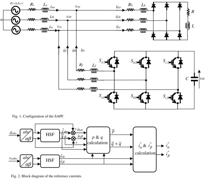
Fig. 1 shows the power circuit configuration of shunt active power filter for the compensation of harmonics generated by a nonlinear load.
The SAPF studied in this paper is normal in structure, which is composed of a grid-connected three-phase voltage source inverter (VSI), with line inductors Lf in the ac side and
the dc capacitor Cdc in the dc side. The control scheme mainly
contains two parts: harmonic extraction method and current control loop.
III. REFERENCE CURRENT CALCULATION
Many approaches such as notch filter, instantaneous p–q method, modified p–q method, synchronous detection method, synchronous d–q frame method , flux based control and non-linear least squares approach are used in active power filter applications.
In this paper, we propose a new harmonic detection method, based on a (HSF) and this algorithm works effectively not only under balanced supply voltages, but also under distorted or unbalanced conditions.
In this method the reference current signal is derived from the measured quantities by the use of the instantaneous reactive power theory associated with two HSFs. The main steps of this method are summarized in the diagram blocks of Fig. 2. The reference currents are identified using a modified version of the instantaneous active and reactive power theory. We used HSF instead of classical harmonic extraction based on high pass filters (HPF) or low pass filters (LPF). The HSF is dedicated to extract the fundamental component directly from unbalanced electrical signals (voltage or current) in α −β reference frame [5], [6], [7], [8].
IV. PREDICTIVE CURRENT CONTROL
The current control suggested in this paper is based on the model predictive approach. The proposed predictive control strategy is based on the fact that only a finite number of possible switching states can be generated by a static power converter and that models of the system can be used to predict the behavior of the variables for each switching state. For the
selection of the appropriate switching state to be applied, a selection criteria must be defined. This selection criteria is expressed as a cost function that will be evaluated for the predicted values of the variables to be controlled. Prediction of the future value of these variables is calculated for each possible switching state. The switching state that minimizes the cost function is selected [9].
The current error for the next sampling instant can be expressed in orthogonal coordinates as follows [9]:
p p i i i i g = α* − α + β* − β (1)
where
i
αp andi
βp are the real and imaginary part of the predicted filtercurrent vector, and are the real and imaginary part of the reference current.The voltage vector that minimizes the current error is selected and the respective switching state is applied to the VSI.
R L RL LL Rs Ls Rf Lf vsa vsb vsc es (a,b,c) isa isb isc iLa iLb iLc ifa ifb ifc C vdc n 1 a S 2 a S 1 b S S c1 2 b S Sc2
Fig. 1. Configuration of the SAPF.
HSF abc αβ p & q calculation * α i & iβ* calculation + + - - HSF abc αβ abc il sabc v α h i β h i α iˆ β iˆ α vˆ β vˆ p ~ q q+ ~
Fig. 2. Block diagram of the reference currents.
* α i * β i
V. SIMULATION RESULTS
For the simulations, Matlab/Simulink and the SimPowerSystem toolbox were used. Various simulation results are obtained under ideal and non-ideal supply conditions. The essential parameters selected for the simulation studies are listed in Table I.
TABLEI SYSTEM PARAMETERS
The total harmonic distortion (THD) of the source currents is taken to evaluate the harmonic elimination performance. A. Performance of the SAPF under Ideal Conditions of the
Supply Voltages
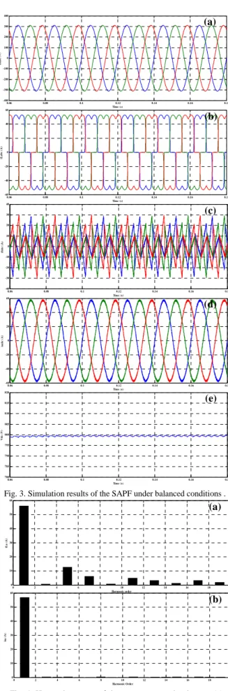
Fig. 3(a)–(e) shows the waveforms of the supply voltages, source current without any filter connected in the system, the compensating current , source current when SAPF is connected and dc-link capacitor voltage respectively. The average percentage THD of source current is 27.22% without compensation, which reduces to 1.84% after connecting SAPF. The harmonic spectra of the phase-a load current and source current after compensation are shown in Fig. 4(a) and (b).
It can be clearly seen that the three-phase load current is seriously distorted with the nonlinear load. When the control strategy is applied to the SAPF, three-phase source current becomes balanced and sinusoidal. The dc-link capacitor voltage is adequately controlled around its reference value Vdc
with a very slight ripple, showing that the proposed control strategy is effective.
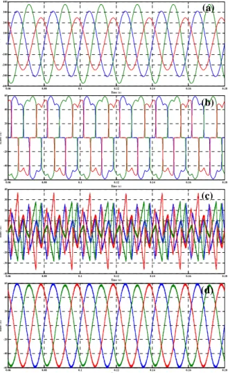
B. Performance of the SAPF under Non- Ideal Conditions of the Supply Voltages
For testing the performance of proposed SAPF configuration under unbalanced source voltages, the system is supplied with voltages as follows: values of grid voltages of phases “a”, “b”, and “c” are 220, 265, and 175 V, respectively. In this case, the unbalanced AC voltages of the power grid are presented in Fig. 5(a). The source currents delivered by the nonlinear load feeding by this unbalanced power grid are presented in Fig. 5(b). In this graph, the load currents became more distorted. Parameter Value AC Supply voltage 220 V(rms) Supply resistor 2 mΩ Supply inductor 0.01 mH Supply frequency 50 Hz Load AC resistor 1.2 mΩ Load AC inductor 0.3 mH DC voltage 800 V DC capacitor 8.8 mF Filter resistor 0.2 Ω Filter inductor 2 mH
Rectifier load resistor 10 Ω
Rectifier load inductor 5 mH
0.06 0.08 0.1 0.12 0.14 0.16 0.18 -400 -300 -200 -100 0 100 200 300 400 Time (s) es a b c (V ) 0.06 0.08 0.1 0.12 0.14 0.16 0.18 -60 -40 -20 0 20 40 60 Time (s) iL a b c (A ) 0.06 0.08 0.1 0.12 0.14 0.16 0.18 -40 -30 -20 -10 0 10 20 30 40 Time (s) if a b c (A ) 0.06 0.08 0.1 0.12 0.14 0.16 0.18 -60 -40 -20 0 20 40 60 Time (s) is a b c ( A ) 0.06 0.08 0.1 0.12 0.14 0.16 0.18 780 785 790 795 800 805 810 815 820 Time (s) V d c ( V )
Fig. 3. Simulation results of the SAPF under balanced conditions . (a) (b) (c) (d) (e) 0 2 4 6 8 10 12 14 16 18 20 0 10 20 30 40 50 60 Harmonic order iL a ( A ) 0 2 4 6 8 10 12 14 16 18 20 0 10 20 30 40 50 60 Harmonic Order is a ( A )
Fig. 4. Harmonic spectra of the source current in phase-a: (a) before and (b) after compensation.
(a)
When the compensation scheme is introduced in the SAPF, the resultant source currents are almost sinusoidal and balanced as shown in Fig. 5(d). The THD of the source currents before compensation are respectively 27.32%, 22.79% and 32.95% while those are equal to 2.11%, 1.80% and 1.84% after compensation.
VI. CONCLUSION
This study has investigated predictive current control of shunt active power filter under unbalanced supply voltage conditions. The SAPF is controlled based on predictive control to eliminate the harmonics. The controller was also tested under severe supply voltage disturbance. The proposed control is easy to implement and it shows robustness and very good performance in both balanced supply voltages and unbalanced conditions.
REFERENCES
[1] H. Akagi, “New trends in active filters for power conditioning,” IEEE Trans. Ind. Appl., vol. 32, pp. 1312-1322, Nov./Dec. 1996.
[2] E.E. EL-Kholy, A. EL-Sabbe, A. El-Hefnawy, and H. M. Mharous, “Three-phase active power filter based on current controlled voltage source inverter,” Elect. Power and Energy Syst. , vol. 28, pp. 537-547, 2006.
[3] R.L. de Araujo Ribeiro, C.C. de Azevedo, and R.M. de Sousa, “A robust adaptive control strategy of active power filters for power-factor correction, harmonic compensation, and balancing of nonlinear loads, ” IEEE Trans. Power Electron., vol. 27, pp. 718-730, Feb. 2012. [4] T. Zaveri, B. Bhalja, and N. Zaveri, “Comparison of control strategies
for DSTATCOM in three-phase, four-wire distribution system for power quality improvement under various source voltage and load conditions, ” Elect. Power and Energy Syst., vol. 43, pp. 582-594, 2012.
[5] S. Karimi, P. Poure, and S. Saadate, “High performances reference current generation for shunt active filter under distorted and unbalanced conditions, ” in Proceeding of Power Electronics Specialists Conference. IEEE, pp. 195-201, 2008.
[6] M. Abdusalam, P. Poure, and S. Saadate, “Study and experimental validation of harmonic isolation based on high seletivity filter for three-phase active filter, ” in Proceeding of IEEE International Symposium Ind. Electron. ISIE 2008, pp. 166-171, 2008.
[7] M. Abdusalam, P Poure, S. Karimi, and S. Saadate, “New digital reference current generation for shunt active power filter under distorted voltage conditions. Electr. Power Syst. Res., vol. 79, pp. 759-765, 2009. [8] N. Mesbahi, A. Ouari, D. Ould Abdeslam, T. Djamah, and A. Omeiri,
“Direct power control of shunt active filter using high selectivity filter (HSF) under distorted or unbalanced conditions”, Electr. Power Syst. Res., vol. 108, pp. 113-123, March 2014.
[9] J. Rodríguez, J. Pontt, C. A. Silva, P. Correa, P. Lezana, P. Cortés , and U. Ammann,“ Predictive current control of a voltage source inverter,” IEEE Trans. Ind. Electron., vol. 54, pp. 495-503, Feb. 2007.
0.06 0.08 0.1 0.12 0.14 0.16 0.18 -400 -300 -200 -100 0 100 200 300 400 Time (s) es a b c ( V ) 0.06 0.08 0.1 0.12 0.14 0.16 0.18 -60 -40 -20 0 20 40 60 Time (s) iL a b c (A ) 0.06 0.08 0.1 0.12 0.14 0.16 0.18 -40 -30 -20 -10 0 10 20 30 40 Time (s) if a b c (A ) 0.06 0.08 0.1 0.12 0.14 0.16 0.18 -60 -40 -20 0 20 40 60 Time (s) is a b c (A ) (a) (b) (c) (d)
Fig. 5. Simulation results of the SAPF under unbalanced conditions. .