HAL Id: hal-03199464
https://hal.inria.fr/hal-03199464
Submitted on 15 Apr 2021
HAL is a multi-disciplinary open access
archive for the deposit and dissemination of
sci-entific research documents, whether they are
pub-lished or not. The documents may come from
teaching and research institutions in France or
abroad, or from public or private research centers.
L’archive ouverte pluridisciplinaire HAL, est
destinée au dépôt et à la diffusion de documents
scientifiques de niveau recherche, publiés ou non,
émanant des établissements d’enseignement et de
recherche français ou étrangers, des laboratoires
publics ou privés.
Verification
Cláudio Lourenço, Denis Cousineau, Florian Faissole, Claude Marché, David
Mentré, Hiroaki Inoue
To cite this version:
Cláudio Lourenço, Denis Cousineau, Florian Faissole, Claude Marché, David Mentré, et al.. Formal
Analysis of Ladder Programs using Deductive Verification. [Research Report] RR-9402, Inria. 2021,
pp.25. �hal-03199464�
0249-6399 ISRN INRIA/RR--9402--FR+ENG
RESEARCH
REPORT
N° 9402
April 2021Ladder Programs using
Deductive Verification
Cláudio Belo Lourenço, Denis Cousineau, Florian Faissole, Claude
Marché, David Mentré, Hiroaki Inoue
RESEARCH CENTRE SACLAY – ÎLE-DE-FRANCE
1 rue Honoré d’Estienne d’Orves Bâtiment Alan Turing
Cláudio Belo Lourenço
†, Denis Cousineau
‡, Florian Faissole
‡,
Claude Marché
†, David Mentré
‡, Hiroaki Inoue §
Project-Team Toccata
Research Report n° 9402 — April 2021 — 25 pages
Abstract: Programmable logic controllers (PLC) are industrial digital computers used as automation controllers of manufacturing processes, such as assembly lines or robotic devices. The Ladder language, also known as Ladder Logic, is a programming language used to develop PLC software. Because of their widespread usage in industry, verifying that Ladder programs conform to their expected behaviour is of critical importance.
In this work, we consider the description of the expected behaviour under the form of a timing chart, describing scenarios of execution. Our approach consists in translating the Ladder code and the timing chart into a program for the Why3 environment dedicated to deductive program verification. The verification proceeds by generating formal verification conditions, which are mathematical statements to be proved valid using automated theorem provers.
The ultimate goal is two-fold: first, by obtaining a complete proof, we can verify the conformance of the Ladder code with respect to the timing chart with a high degree of confidence. Second, when the proof is not fully completed, we obtain a counterexample, illustrating a possible execution scenario of the Ladder code which does not conform to the timing chart.
Key-words: Formal specification, Deductive verification, Ladder language for programming PLCs, Why3 environment for deductive verification.
*This work has been partially supported by the bilateral contract ProofInUse-MERCE between Inria team Toccata and
Mit-subishi Electric R&D Centre Europe, Rennes.
†Université Paris-Saclay, CNRS, Inria, LMF, 91405, Orsay, France ‡Mitsubishi Electric R&D Centre Europe, Rennes, France §Mitsubishi Electric Corporation, Amagasaki, Japan
Résumé : Les Programmable Logic Controllers (PLC) sont des dispositifs numériques industriels util-isés pour contrôler les processus de fabrication automatutil-isés, tels que les lignes d’assemblage ou les robots de toute sorte. Le langage Ladder, également connu sous le nom de Ladder Logic, est un langage de pro-grammation utilisé pour développer des logiciels pour PLC. Du fait de leur utilisation très répandue dans l’industrie, vérifier que les programmes Ladder sont conformes à leur comportement attendu est d’une importance cruciale.
Dans ce travail, nous considérons une description du comportement attendu sous la forme d’un timing chart, décrivant les scénarios d’exécution. Notre approche consiste à traduire le code Ladder et le timing chart en un programme pour l’environnement Why3 dédié à la vérification déductive des programmes. La vérification se déroule en générant des conditions formelles de vérification, qui sont des énoncés mathématiques destinés à être prouvés valides à l’aide de prouveurs automatiques de théorèmes.
Le but ultime est double : premièrement, en obtenant une preuve complète, nous pouvons vérifier la conformité du code Ladder par rapport au timing chart avec un degré élevé de confiance. Deuxième-ment, lorsque la preuve n’est pas entièrement complétée, nous obtenons un contre-exemple, illustrant un scénario d’exécution possible du code Ladder qui n’est pas conforme au timing chart.
Mots-clés : Spécification formelle, preuve de programmes, langage Ladder pour la programmation des PLC, environnement Why3 pour la vérification déductive.
Contents
1 Introduction 5
2 Introduction to Ladder Programming 6
2.1 Ladder Logic . . . 6
2.2 Specification of Expected Behaviour . . . 7
3 The Why3 Environment 9 3.1 Automatic Generation of Loop Invariants . . . 10
3.2 Generation of Counterexamples . . . 11
4 Translation of Ladder code to WhyML 12 4.1 Translation of the Ladder program . . . 12
4.2 Ladder loop and timing charts . . . 14
4.2.1 Events and stable states as loops . . . 14
4.2.2 Timer-related sequences of events . . . 15
5 Implementation and Experimental Results 17 5.1 Overview of the Approach . . . 17
5.2 Results on correct code . . . 18
5.3 Results on incorrect code . . . 18
5.3.1 Error scenarios . . . 18
5.3.2 First incorrect program . . . 19
5.3.3 Second incorrect program . . . 19
5.3.4 Qualitative analysis of the experiments . . . 20 6 Discussions, Related Work and Future Work 22
List of Figures
1 Carriage line control example . . . 6
2 Carriage line control timing chart specification . . . 7
3 Toy example of a WhyML program with a formal contract . . . 9
4 WhyML function for SET instruction . . . 12
5 WhyML function for PLS instruction . . . 12
6 WhyML code for timers . . . 13
7 WhyML code for Carriage Ladder program . . . 13
8 WhyML formalisation of event ]1 and stable state ](1 ,→ 2) . . . 14
9 WhyML formalisation of event ]5 and stable state ](5 ,→ 6) . . . 15
10 Output of the tool on the nominal carriage line control program . . . 18
11 Incorrect versions of the carriage line control Ladder program . . . 19
12 First incorrect Ladder program: analysis results . . . 20
1
Introduction
Programmable logic controllers (PLC) are industrial digital computers used as automation controllers of manufacturing processes, such as assembly lines or robotic devices. PLCs can simulate the hard-wired relays, timers and sequencers they have replaced, via software that expresses the computation of outputs from the values of inputs and internal memory. The Ladder language, also known as Ladder Logic, is a programming language used to develop PLC software. This language uses circuit diagrams of relay logic hardware to represent a PLC program by a graphical diagram. This language was the first available to program PLCs, and is now standardised in the IEC 61131-3 standard [22]. It is one language among other languages for programming PLCs, and is still widely used and very popular among technicians and electrical engineers.
Because of the widespread usage of PLCs in industry, verifying that a given Ladder program is con-forming to its expected behaviour is of critical importance. In this work, we consider the description of the expected behaviour under the form of a timing chart, describing scenarios of execution. Our approach consists in automatically translating the Ladder code and the timing chart into a program written in the WhyML language, which is the input language of the generic Why3 environment for deductive program verification. In WhyML, expected behaviours of program are expressed using contracts, which are an-notations expressed in formal logic. The Why3 environment offers tools for checking that the WhyML code conforms to these formal contracts. This verification process is performed using automated theorem provers, so that at the end, if the back-end proof process succeeds, the conformance of the Ladder code with respect to the timing chart is verified with a high degree of confidence. Yet, a complete formal proof is not the only expected feedback from our tool chain: we also want to obtain useful feedback when the proof does not fully succeed. More precisely, in such a case of proof failure, we aim at obtaining counterexampleswhich must illustrate a possible execution scenario of the Ladder code which does not conform to the timing chart.
In the remaining of this report, we start in Section 2 by introducing the basics of Ladder programming, and the way their expected behaviours are expressed using timing charts. In Section 3 we introduce the Why3 features that are needed for the translation of Ladder code and timing charts into WhyML programs, which is described in Section 4. Section 5 presents our experiments and their results, both in the case of complete proof success and in the case of proof failures, where counterexamples are generated. We present related work and future work in Section 6.
(a) System’s description (b) Ladder program
Figure 1: Carriage line control example
2
Introduction to Ladder Programming
2.1
Ladder Logic
A Ladder program (a diagram) takes inputs values (contacts) that correspond to the fact that physical relays are either wired, not wired, pulsing (rising edge) or downing (falling edge), and other values stored in the internal memory of the PLC (Boolean values, integers, floating-point, strings, etc.). A Ladder program can output Boolean values to the physical relays of the factory (coils) or it can call instructions, that may modify the values of the internal memory of the PLC (devices). Graphically, contacts are located at the left of the diagram. They can be combined in a serial way or in a parallel way (the obtained value is then the conjunction, resp. the disjunction, of the two contact values). Coils and instructions are activated when the combination of contacts at their left gives a wired value, and they can also be parallelised (in that case, there are either all activated or all deactivated). A line with contacts, coils and instructions is called a rung, and a program is composed of several rungs. Such a Ladder program is executed cyclically in a synchronous way: first inputs are read, then the program is executed and eventually outputs are written. One single execution of the program is called a scan.
A rather simple example of a carriage line control PLC system is depicted in Figure 1a while the corresponding Ladder program is depicted in Figure 1b. This example comes from a Mitsubishi Electric training manual for programming PLCs [19]. We illustrate Ladder’s principles on the first rung of this example: this rung expresses the fact that output Y70 receives the value of the Boolean formula (X0 ∨ Y70) ∧ (¬ M2)) (i.e. if the corresponding physical devices are activated such that the Boolean formula is true, then Y70 is activated, and it is deactivated otherwise).
The program also makes use of Ladder instructions SET, RST and PLS. The SET instruction activates its device argument (either an internal memory device or an output device) when its input is activated, and does nothing otherwise. For instance, in the example of Figure 1b, Y71 is activated when both the common front (X0 ∨ Y70) ∧ (¬ M2) and the internal memory device M1 are activated. The RST instruction is the opposite: the device argument is deactivated when the instruction’s input is activated. The PLS (pulse) instruction activates its device argument on a rising edge of its input, i.e. when the instruction’s input has just been activated, then it deactivates its device argument on the next scan.
The diagram also uses a timer instruction on a special device T0 which is activated once the timer finishes. When its input is activated, the instruction sets the threshold (30) of the timer and increments a counter. After 30 consecutive scans in which both the common front and output Y73 are activated, the device T0 is activated (and it remains activated until the input of the timer instruction is deactivated).
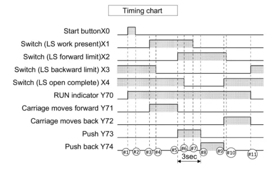
Figure 2: Carriage line control timing chart specification
2.2
Specification of Expected Behaviour
Because of its synchronous nature, the language hardly lends itself to exhaustive functional specifications. Since the work made on AutomationML [11] by an industrial and academic consortium, the practice, among PLC designers, is to use the timing chart paradigm, which describes the expected behaviour of the PLC for a nominal execution scenario. A timing chart specifies the evolution of outputs over the program execution’s scans according to the evolution of inputs. It is made of a succession of events, i.e. scans with either changes of inputs that may lead to changes of outputs, or endings of timers that lead to changes of outputs. Events are separated by stable states, i.e. arbitrary-length successions of scans in which the values of both inputs and outputs are unchanged.
Figure 2 depicts the timing chart specification of the carriage line control example. Events of the timing chart are depicted as ]1, ]2, . . . , ]11. In the rest of the paper, we use the notation ](1 ,→ 2), . . . , ](10 ,→ 11) to depict stable states. The initial and final states of the timing chart are respec-tively depicted by ]idle and ]end.
The timing chart of Figure 2 also contains a fixed-duration sequence of events and stable states (rep-resented by an arrow, between events ]5 and ]8), whose duration is 3 seconds. We call fixed-duration sequencethe concerned sequence of events and stable states. Typically, the Ladder program is executed periodically every 100 milliseconds, therefore, the fixed-time period of 3 seconds is made of 30 scans. Here, the given implementation uses the timer device T0 in order to satisfy this aspect of the specification. The main goal of this paper is the verification that the Ladder diagram conforms to such a timing chart specification. A first idea would be to envision the use of deductive verification techniques, in the wake of our previous work on Ladder instruction-level verification [8]. However, not all variables used in the Ladder program of Figure 1b are addressed by the timing chart. Indeed, internal memory devices (e.g. M1 and M2) and timers (e.g. T0) are introduced by the developer in order to make the program satisfy its specification, but do not belong to this specification. As an example, in the carriage line control program, the M2 device acts as a termination flag which stops the execution of the PLC as soon as it is
activated. There is no doubt that M2 remains false in the timing chart scenario’s execution. However, as it will be illustrated in Section 3 below, deductive verification would lack this information to check that outputs satisfy their specification. This kind of issue is at the heart of the strategy that we propose in this report, that is to integrate a method for inferring loop invariants, using a technique that will be described below in Section 3.1.
val b : ref bool
val x : ref int
let toy () : unit
requires { 0 <= !x <= 10 } writes { b, x } ensures { not !b } ensures { !x <= 200 } = b := false; while (!x < 100) do b := (!x < 50); if !b then x := !x + 2 else x := !x + 3; done; assert { !x >= 75 }
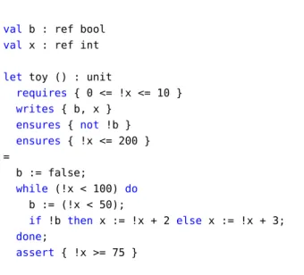
Figure 3: Toy example of a WhyML program with a formal contract
3
The Why3 Environment
Why3 is a generic environment for deductive program verification (seehttp://why3.lri.fr), providing the language WhyML for specification and programming [14, 5, 15]. The genericity of Why3 is exem-plified by the fact that WhyML is already used as an intermediate language for verification of programs written in C, Java or Ada [13, 17]. The specification component of WhyML [4], used to write program annotations and background theories, is an extension of first-order logic. The specification part of the language serves as a common format for theorem proving problems, proof tasks in Why3’s jargon. Why3 generates proof tasks from user lemmas and annotated programs, using a weakest-precondition calculus, then dispatches them to multiple provers. It is indeed another aspect of the genericity of Why3: its ability to dispatch proof tasks to many different provers. In practice, for the proof of programs, provers of the SMT (Satisfiability Modulo Theories) family are the most successful ones, indeed at least if they support quantified formulas, which is the case for Alt-Ergo [7], CVC4 [1] and Z3 [10].
We illustrate the main Why3 features we need on a toy WhyML program presented in Figure 3. This code involves two global variables,bof type Boolean andxof type integer, that is a mathematical, unbounded integer in WhyML. The functiontoy takes no arguments, and is equipped with a formal contract involving first a pre-condition (introduced by keywordrequires) stating that the value ofxon function entrance is required to lie between 0 and 10, and two post-conditions (introduced by keyword
ensures) stating respectively that at exit, bis false and thatxis smaller than 200. The clausewrites
expresses which global variables are potentiallly modified by that function. Notice the WhyML syntax for mutable variables, inspired by ML, requiring to write a bang symbol to access their values. The body of that function is a simple imperative code involving a while loop and a conditional. This code ends by an other kind of formal annotations, namely a code assertion stating that the value ofxmust be greater or equal to 75 after the loop.
Given such an annotated code, the Why3 core engine generates 3 verification conditions (VCs), cor-responding to the assertion and the two post-conditions. When calling provers for attempting to prove these VCs, only the one for the assertion is proved valid. Indeed, this assertion directly follows from the negation of the loop condition, which entails that the value ofxis not smaller than 100. On the other hand, none of the post-conditions are proved valid. This is naturally expected in the classical setting
of deductive verification, because for proving properties about loops one should state appropriate loop invariants. For example, we can add such an invariant in our toy example as follows:
...
while (!x < 100) do
invariant { 0 <= !x <= 150 } b := (!x < 50);
...
With that change, Why3 now generates additional VCs, stating that this invariant initially holds when entering the loop, and that it is preserved by an arbitrary iteration of the loop body. These extra VCs are proved valid, and now the VC corresponding to the second post-condition is proved valid too, because is a consequence of the loop invariant being true at exit of the loop. Yet, the first post-condition is still not proved valid, there is a need to make the loop invariant stronger.
For the work presented here, we make use of two specific and still quite experimental features of Why3, namely the capability of automatically generating loop invariants, and the capability of generating counterexamplesfrom failed proof attempts. The motivation for implementing these features came from former industrial applications, in particular the use of Why3 inside the Spark/Ada environment for the development of safety-critical applications [18].
3.1
Automatic Generation of Loop Invariants
The WhyML code that will be automatically generated from Ladder code and a associated timing chart is mostly a sequence of while loops, operating on quite a large number of variables. As seen above, and as usual in deduction-based program verification, proving those programs with loops require to insert appropriate loop invariants, that in principle should be written by the user.
Nevertheless, in the context of this paper, the objective is to build a fully automatic tool for bringing deductive verification of timing charts specifications to Ladder developers, for whom writing the appro-priate loop invariants by hand would be a tedious and difficult task. Fortunately, there exist methods to automatically infer such invariants, in particular the technique of abstract interpretation, which roughly consists in computing an over-approximation of all the reachable program states, from any possible exe-cution. For our work, we built upon a former prototype for Why3 designed in 2017 [2]. This prototype uses the Apron [16] library to support integer abstraction domains such as intervals, octagons or polyhe-dra. In fact, it appeared that the prototype above was not sufficiently complete for our purpose, we had in particular to add some dedicated support for Boolean variables.
We illustrate that process on our toy example above. Instead of adding a loop invariant, we instruct Why3 to use abstract interpretation to automatically infer such a loop invariant. In practice we have to declare the domain we want to use, here we use the polyhedra domain. The generated loop invariant is then as follows: ... while (!x < 100) do invariant { (!b = false ∧ 0 <= !x <= 10) ∨ (!b = true ∧ 2 <= !x <= 51) ∨ (!b = false ∧ 53 <= !x <= 102) } b := (!x < 50); ...
with this loop invariant added, all the VCs generated are automatically proved valid, including the initial-isation and preservation of that loop invariant, and also the first post-condition that was not proved with the manually added loop invariant.
3.2
Generation of Counterexamples
When a given proof task fails to be proved, we need to have some feedback so as to understand why it is not proved. In Why3, when a proof is attempted with an SMT solver, and the goal is not proved, then the solver is able to propose a model, which is supposed to contradict the goal. The Why3 core implements an approach that turns such a model, expressed at the level of the proof task, back to a potential counterexampleexpressed at the level of the source code [9].
Let’s illustrate this feature again on our toy example. Assume that we introduce a modification of the code, changing the loop condition as follows.
...
while (!x < 300) do
...
Still assuming that we ask to generate a loop invariant, all generated VCs are proved except the second post-condition. For this VC, Why3 propose a counterexample where the values ofbandxat loop exit are respectivelyfalseand 300. Indeed, these values satisfy the loop invariant, but with those the post-condition!x <= 200is not valid.
Notice that for the use of this feature to our use case of verifying Ladder code, there is a challenge to address that is to turn the potential counterexample proposed by Why3 into a meaningful counterexample at the level at the Ladder code and the timing chart.
let set (input : bool) (device : ref bool) : unit
writes { device }
ensures { !device ↔ (input ∨ old !device) } =
if input then device := true
Figure 4: WhyML function for SET instruction
let pls (input : bool) (m : ref bool) (cc_input : ref bool) : unit
writes { m, cc_input }
ensures { !m = (input && (not !(old cc_input))) ∧ !cc_input = input } =
m := (input && not !cc_input) ; cc_input := input
Figure 5: WhyML function for PLS instruction
4
Translation of Ladder code to WhyML
Our prototype automatically translates Ladder programs given as XML files and timing charts given as PlantUML [23] files into WhyML programs. We describe in Section 4.1 how we translate the Ladder program itself, and in Section 4.2 how we use this translation for modeling the successive executions of the program and verifying that it satisfies the given timing chart.
4.1
Translation of the Ladder program
Our translation relies on predefined models of Ladder instructions as WhyML functions.
For example, Figure 4 depicts the function that corresponds to the SET instruction. This function takes two arguments, first the input of the instruction (whether it should be activated or not), and second the device on which it may have an effect. Both the code and the contract of the function state the intended behaviour of the SET function: if the instruction is activated then the considered device is activated (otherwise its value does not change). The WhyML function for the RST instruction is very similar.
The WhyML function for instruction PLS is given in Figure 5. Besides the input and device argu-ments, it introduces another variable argument (cc_input) for memorising the value of the input at the previous scan. Then it uses this value to activate the device argument if and only if the input argument is activated at this scan while it was not at the previous scan.
In Figure 6, we describe how we model timers. First we use a record type with two fields: current
that gives the current value of the timer counter andsettingthat gives the threshold of the timer. Then, we model the timer instruction with the timer_coilfunction. As for Ladder timers, this instruction, when activated, sets the threshold of the timer and increment its counter. When it is deactivated, it resets the counter to zero (remind that the timer instruction should be activated during a number of consecutive scans that correspond to the threshold, for the timer to end). Thetimer_contactfunction models the fact that the timer device is activated when its counter reaches its threshold value.
Given those Ladder instructions formalisations, we can now give the translation of the full Ladder program of Figure 1b, which we give in Figure 7.
type timer = {
mutable current : int;
mutable setting : int; }
let timer_coil (input : bool) (t : timer) (v : int) : unit
writes { t }
ensures { t.setting = v
∧ ((input ∧ t.current = (old t.current) + 1)
∨ ((not input) ∧ t.current = 0)) } =
if input then (t.current ← (t.current + 1); t.setting ← v)
else (t.current ← 0; t.setting ← v)
let timer_contact (t : timer) : bool
returns {result → result = (t.current >= t.setting) } =
(t.current >= t.setting)
Figure 6: WhyML code for timers
let common_1 = (!x0 || !y70) && (not !m2) in
y70 := common_1;
let common_2 = !x1 && !x3 in
pls (common_1 && common_2) m1 cc0;
let common_3 = !m1 in
set (common_1 && common_3) y71;
let common_4 = !y71 && !x2 in
rst (common_1 && common_4) y71; set (common_1 && common_4) y73;
let common_5 = !y73 in
timer_coil (common_1 && common_5) t0 30;
let common_6 = timer_contact t0 in
rst (common_1 && common_6) y73; set (common_1 && common_6) y74;
let common_7 = !y74 && !x4 in
rst (common_1 && common_7) y74; set (common_1 && common_7) y72;
let common_8 = !y72 && !x3 in
rst (common_1 && common_8) y72; m2 := common_1 && common_8
(* Ladder program’s body *)
(* ... *)
x0 := randomb();
while (!x0 && not !x1 && not !x2 && !x3 && !x4) do
invariant { !y70 && not !y71 && not !y72 && not !y73 && not !y74 }
(* Ladder program’s body *)
(* ... *)
x0 := randomb();
done
Figure 8: WhyML formalisation of event ]1 and stable state ](1 ,→ 2)
4.2
Ladder loop and timing charts
By definition, timing charts are made of successive events and stable states. Checking that a program is conforming to a timing chart means that, under the hypotheses on input values, the values of outputs are correct according to the order of appearance of events and stable states in the timing chart scenario. In addition, fixed-time duration information (timer-related sequence of events) also need to be verified. We propose and implement an automatic process that takes a Ladder diagram and a timing chart specification and returns the corresponding WhyML formalisation.
4.2.1 Events and stable states as loops
The formalisation is made of a succession of do-while loops1 (except for the initial stable state of the
timing chart). The body of each loop corresponds to the WhyML formalisation of one Ladder program’s scan. Each do-while loop corresponds to a pair made of an event (the first iteration do) and the following stable state (while). The guard of the loop corresponds to the assumptions on inputs, i.e. the values taken by the inputs at the corresponding event and during the following stable states. The verification conditions on outputs are modelled as loop invariants: the invariant initialisation corresponds to the event while its preservation corresponds to the stable state.
The initial state of the timing chart (values of devices before the PLC starts) is handled in its own way. Basically, all outputs and internal memory devices are initially deactivated. The initial values of inputs are read at the beginning of the timing chart. The initial state is formalised as a while loop (and not a do-while loop) whose guard corresponds to the values of inputs at the initialisation of the timing chart. Indeed, the initial state of the timing chart is a stable state which does not begin with an event. The invariants to be proved for this loop correspond to the fact that outputs remain deactivated.
The events last during one scan, while stable states have an arbitrary duration and end when the next event is reached, i.e. when an input changes or a timer coils. In order to model this behaviour, the body of each loop iteration is enriched with an assignment of the concerned input to an arbitrary Boolean value, that may or may not update its value and lead to a new event. For that purpose, we rely on a WhyML functionrandombtaking no argument and returning an arbitrary Boolean value.
The WhyML code of Figure 8 gives an example of formalisation of an event. It is for the event ]1 and the stable state ](1 ,→ 2), the latter being terminated when event ]2 is reached, i.e. when x0
is deactivated. Deductive verification is unfortunately not sufficient to directly prove the invariants on outputs. Indeed, as mentioned in Section 2.2, the specification used to generate the formalisation lacks
1There are no do-while loop in WhyML, we just mean by do-while loop a code piece of the following form with two occurrences
(* Ladder program’s body *)
(* ... *)
x4 := randomb(); c1 := !c1 + 1;
while (not !x0 && !x1 && not !x2 && !x3 && !x4 && !c1 < 29) do invariant { !y70 && not !y71 && not !y72 && !y73 && not !y74 }
(* Ladder program’s body *)
(* ... *)
x4 := randomb(); c1 := !c1 + 1;
done;
assume { !c1 < 29 }
Figure 9: WhyML formalisation of event ]5 and stable state ](5 ,→ 6)
information on internal memory devices. To bypass this difficulty, we rely on the invariant generation plug-in for Why3 (already presented in Section 3.1) to generate additional loop invariants for each while loop of the formalisation. For instance, in each loop of the formalisation, the inference of the invariant
not !m2would be needed.
4.2.2 Timer-related sequences of events
One of the most technical points of our work concerns the formalisation of fixed-duration sequences, e.g. events/stable states ]5 to ]8 in the timing chart of the carriage line control (Figure 2).
We have to catch the fact that the total duration of this sequence is exactly 3 seconds. Since timing charts specifications do not make explicit which timer device is used to implement this aspect, we cannot, in the general case, guess which timer device appearing in the code is used for any of the fixed-duration sequences appearing in the timing chart. That is why we introduce a fresh internal counter for each fixed-duration sequence of the timing chart, add the fixed-duration constraint in the guard of each loop associated to the concerned stable states and increment the counter’s value at each loop iteration. The timer is incremented accordingly, therefore, the counter is supposed to reflect the timer’scurrentvalue.
In addition, there are two ways to reach the end of the loops corresponding to intermediate stable states of the fixed-duration sequences: an input change and the maximal number of scans being reached by the counter’s value. We have to catch the fact that the termination of intermediate stable states (](5 ,→ 6) and ](6 ,→ 7) in our example) is due to an input update and not because the maximal number of scans has been reached. To enforce this property, we insert anassumeclause after loop’s end.
In the example of Figure 2, we callc1the counter associated with the 3 seconds fixed-duration se-quence. As an illustration, we give the shape of the formalisation of event ]5 and stable state ](5 ,→ 6), ending with the deactivation of X4 while the number of elapsed scans of the fixed-duration sequence is not reached yet. The resulting WhyML code is given on Figure 9. For stable state ](7 ,→ 8), i.e. the last stable state before the end of the fixed-duration sequence, there is only one way to end the loop (!c1 >= 29) so there is no need for anyassumeclause.
Note that the condition we use is!c1 < 29and not!c1 <= 29(or equivalently!c1 < 30). The reason is technical: at the end of the stable state ](7 ,→ 8), the counter reaches the value 29. The timer’s current value is also equal to 29. Event ]8’s scan begins and the current value of the timer is incremented during its execution (more precisely at rung 5), therefore, its value becomes equal to 30 and the timer coils.
explicit the equality between the introduced counterc1and the timer device’scurrentvalue in the for-malisation of Figure 9. Nonetheless, we can benefit from the invariant inference mechanism presented in Section 3.1. Indeed, unlike classical abstract interpreters like Frama-C EVA/Value [6] or Apron [16], the plug-in does not only compute numerical domains for the variables of the program. It makes use of these domains (provided by Apron) to infer propositional relations between variables. In particular, we successfully obtain the invariant!c1 = t0.currentthat makes explicit the role of the introduced counter.
5
Implementation and Experimental Results
Our first goal is to be able to prove fully automatically that the Ladder program given in Figure 2 is conforming to the timing chart also given in Figure 2. Our secondary goal is that we also want to give back to the user meaningful and easy-to-use information when one tries to prove an incorrect implementation. In Section 5.1, we describe the workflow of the implementation of our approach. Then, Section 5.2 presents the results obtained when executing the analysis on a correct carriage line control implementa-tion, i.e., the implementation of Figure 1b. Finally, in Section 5.3, we present the feedback given by our toolbox when analysing two slight modifications of the nominal program that both make the verification of conformance to the timing chart fail.
5.1
Overview of the Approach
We implemented our approach as follows:
• The tool takes two inputs: an XML representation of the Ladder program and a timing chart speci-fication, written in the PlantUML language.
• It translates the Ladder program as a WhyML program.
• It derives, from the timing chart the different guard conditions (hypotheses on input values) and invariants (output values to prove) for formalising the successive events of the timing chart. • Then, for each event,
– Why3 infers a loop invariant for the WhyML loop that models the state that is associated to the event (adding information on values of internal memory to the information on output values computed in the previous step).
– Why3 computes the proof obligations that correspond both to the inferred invariant and the in-variant that corresponds to the timing chart specification, and dispatches them to SMT solvers. • And so on for the next events. Note that besides the hypotheses on the values of inputs and out-puts at the start of the event, which are given by the timing chart, the proving process also needs hypotheses on the values of internal memory values at the event’s beginning. Those values are given by the loop invariant inferred for the previous event. Hence we store, during the process, the inferred invariants for each event in order to use them as preconditions for the next event.
• If a proof obligation fails at event n, we build a WhyML program concatenating all the previous events and the faulty one, with loops enriched with the consecutively inferred invariants. Provers are called on this WhyML program and provide counterexamples (see Section 5.3).
• On the contrary, if all events and stable states are proved, we conclude that the Ladder program satisfies the timing chart specification.
This approach of proving each event, one by one, until a specification violation is detected, is moti-vated by the fact that abstract interpretation, in our examples, is far more time-consuming than proving. In the case a violation is detected, our approach allows not to launch abstract interpretation for all the events that follow the one for which the violation has been detected.
Figure 10: Output of the tool on the nominal carriage line control program
5.2
Results on correct code
We apply our approach on the nominal Ladder program described in Figure 1b, for which we successfully verify the timing chart specification. Figure 10 depicts the result we obtain when running the analysis. In accordance with our strategy presented in Section 5.1, we consecutively infer invariants and then prove verification conditions for each event/stable state, starting from the initial (idle) state of the timing chart. We observe that abstract interpretation is for now quite expensive, therefore, the proof time is negligible compared to the time for inference of invariants.
5.3
Results on incorrect code
When the verification of a proof obligation fails for a so-called faulty event/stable state, our goal is to provide the most relevant information possible to the user, who may not be used to deductive verifica-tion. Our long-term goal being to build a tool that would be useful to regular Ladder programmers. For that purpose, we propose an error scenario following the timing chart until the faulty event, mixing con-crete values provided by counterexamples generated by Why3 (as described in Section 3.2), and abstract domains provided by abstract interpretation (as described in Section 3.1).
5.3.1 Error scenarios
When, from SMT solvers feedback, Why3 is able to provide a counterexample to a proof obligation coming from the verification of the concatenation of the consecutive events from the first one to the faulty one, the information we get is the values of the inputs, outputs and internal devices at the beginning of each event until the faulty one. Due to the way Why3 handles loops during the computation of verification conditions for SMT-solvers (that is, the loop invariant is the only known fact for the code after the loop, see Section 3), we do not have any information on the values the devices take during the states. We think that this lack of information concerning values of devices during states may be an impediment to the understanding of the cause of the specification violation by the programmer. That is why we propose to enrich the counterexample values with the domains of devices values given by abstract interpretation. This leads to the notion of error scenario that provides:
(a) Incorrect program version 1 (b) Incorrect program version 2
Figure 11: Incorrect versions of the carriage line control Ladder program
• For each event that precedes the faulty one (including the faulty one), the values of devices before the beginning of this event’s scan, obtained from the counterexample trace provided by Why3. • For each stable state that precedes the faulty event, an over-approximation of domains of devices
values, obtained by abstract interpretation.
In order to convince ourselves that this notion of error scenario should be useful to Ladder program-mers, we have implemented different slight modifications of the carriage line control Ladder program that introduce bugs. Two of them are presented in this article. The corresponding Ladder diagrams are depicted in Figure 11. The modifications compared to the original code are encircled.
5.3.2 First incorrect program
The first modification of the Ladder program (Figure 11a) corresponds to the use of the M2 (instead of M1) internal memory device in the contact front of rung 3. When trying to prove this program, our tool outputs a failure’s reason: Y71 is false while it should be activated. We also obtain an error scenario trace, whose last parts are depicted by Figure 12a.
In this example, M2 is responsible of setting Y71 while M1 has this role in the nominal case. As M2 is supposed to be deactivated as long as the PLC runs, the consequence of this change is that Y71 is never activated. We observe that the value of M2 at the beginning of scan of the event 3 is equal to false, so there is no chance that Y71 is activated by the SET instruction. It corresponds to a violation of the third event of the timing chart, as illustrated in Figure 12b.
5.3.3 Second incorrect program
In the second modification (Figure 11b), the timer setting duration is set to 40 scans instead of 30. We use our tool to get the reason of the proof failure, i.e. that Y73 is equal to true while it should be false. The obtained reason is rather intuitive: event 8 corresponds to 30 elapsed scans from timer’s start. As the timer has a duration of 40 scans, it has not ended yet, therefore, Y73 is not reset yet, as highlighted by the error scenario of Figure 13a.
The trace shows that the setting value of the timer (here 40) is not reached. In particular, the current value of the timer is between 3 and 29 in the stable state between events 7 and 8, showing that the current
(a) Output of the tool for incorrect program 1 (b) Timing chart’s violation for incorrect program 1
Figure 12: First incorrect Ladder program: analysis results
event follows 3 other events in the fixed-duration sequence. Moreover, at the beginning of scan of the event 8, the current value of the timer and its associated counter c1 are equal to 29, which is exactly the value we expect when leaving the fixed-duration sequence of events. The timing chart violation is depicted by Figure 13b.
5.3.4 Qualitative analysis of the experiments
As a conclusion, we think that this notion of error scenario mixing concrete values provided by coun-terexamples to VCs, and abstract domains provided by abstract interpretation, should be useful to Ladder programmers in order to understand why a program is not conforming to a given timing chart specifi-cation. A weakness of this approach is that in some cases, the concrete and abstract values might seem irrelevant. For example, for a timer counterc, we might have an abstract domain that states thatccan take all the values between, say, 3 and 29 for a state, but the concrete value given for the next event might be 4 for that same counter. For that example, it means that the loop corresponding to the state is executed exactly once in the error scenario, before executing the next event. In that case, it might be very interesting to use the concrete values of counterexamples to refine the domains of abstract interpretation, in order to provide an even more meaningful error scenario to the programmer. In our example, we could refine the domain [3;29] into [3;4], and even make explicit to the programmer that there is exactly one
(a) Output of the tool for incorrect program 2 (b) Timing chart’s violation for the incorrect program 2
Figure 13: Second incorrect Ladder program: analysis results execution of the program for the considered state.
6
Discussions, Related Work and Future Work
We presented a new method for formally verifying that a given Ladder code complies with an expected behaviour expressed by a timing chart. By translating both the Ladder code and the timing chart to a WhyML program, and making use of the loop invariant generation capability of Why3, we are able to provide a fully automatic process to make such a verification, with a high level of confidence. Moreover, when this proof-based process fails at some point, we have a way to propose an error scenario which exposes why the Ladder code is not conforming to the timing chart. Our method is implemented in a prototype which we experimented on a case study, demonstrating the effectiveness of our approach, both for formally proving the correct version and for providing counterexample scenarios on wrong mutants.
The level of confidence of our approach must be understood in terms of the trusted code base of the whole process. It first relies on the soundness of the translation from Ladder code and timing chart, which is described in Section 4. It also relies on the soundness of the VC generation process of Why3, which is not formally proven correct but validated on numerous applications [5]. Regarding trust in Why3, it is important to notice that the prototype implementation of loop invariant generation is not part of the trusted code base, because the loop invariants generated are later on checked for validity by the VC generation process. It is indeed fortunate to not have to rely on the soundness of this part of Why3 implementation, since we had to make significant extension of it for the current purpose. The last part of the tool chain that must be trusted is the back-end SMT solvers.
Regarding the counterexamples scenarios generated, we have noticed that they are satisfactory on our case study, but due to the inherent incompleteness of counter-model generation with SMT solvers, we cannot guarantee that the generated scenarios are always valid.
Related work. PLC software verification is a vast domain and numerous works have been published on that subject. The majority of them use model-checking to verify functional and temporal properties. A summary of those techniques is given in [21]. The drawback of model-checking is that the verification it provides cannot be exhaustive, it cannot model any possible number of executions during the states of a timing chart, contrary to deductive verification. On the other hand, abstract interpretation has also been used for a long time for verifying software, in particular microcontroller software [12, 20] and PLC software [3] (in combination with model-checking). Contrary to model-checking, abstract interpretation gives a full guarantee when it detects no error in a program, but it is dedicated to compute the possible values of variables during the execution of a program, and is not suited for verifying temporal specifi-cations. Finally, in a previous work [8], some of us used the Why3 deductive verification platform for detecting runtime errors of Ladder programs. This work only considered one single execution of Ladder programs and was therefore also not suited for verifying temporal specifications. To our knowledge, the present paper is the first one to combine abstract interpretation and deductive verification for verifying temporal specifications.
Future work. During our work, we had to improve the loop invariant generation feature of Why3, in particular the support for Boolean values. Even enough for our case study, there is clearly room for improvement on this implementation, required to make the tool chain more efficient. We plan to experiment our method on examples of Ladder programs that require WhyML translations involving arrays, and we have to ensure that the loop invariant generation could succeed when we are mixing all involving data-types: integers, Boolean, arrays, and also bounded integers in the future.
We also identified a need for improvement in the counterexample generation part of the chain. To workaround the inherent incompleteness of the SMT solvers, we are planning to design a technique to double-check the validity of counterexamples a posteriori: we plan to verify that a counterexample is a valid one by symbolically executing the scenario it describes, and detect carefully at which step its behaviour diverges from what the timing chart allows.
On the error scenario side, as explained in the end of Section 5.3.3, the parts of a scenario that come from abstract interpretation domains, that correspond to the possible values of devices during states, could be refined using the concrete values given by the counterexamples for next events. This way, we might propose an even more understandable and useful error scenario to Ladder programmers, in case an error is detected in their code.
A more long-term goal is to augment the trust in the translation from Ladder to WhyML. We have some plans for designing a systematic and automatic validation process to confront our translation against existing test suites for Ladder programs.
References
[1] Clark Barrett, Christopher L. Conway, Morgan Deters, Liana Hadarean, Dejan Jovanovi´c, Tim King, Andrew Reynolds, and Cesare Tinelli. CVC4. In Proceedings of the 23rd international confer-ence on Computer aided verification, CAV’11, pages 171–177, Berlin, Heidelberg, 2011. Springer-Verlag.http://dl.acm.org/citation.cfm?id=2032305.2032319.
[2] Lucas Baudin. Deductive verification with the help of abstract interpretation. Technical report, Univ Paris-Sud, November 2017. https://hal.inria.fr/hal-01634318.
[3] Sebastian Biallas, Stefan Kowalewski, Stefan Stattelmann, and Bastian Schlich. Efficient handling of states in abstract interpretation of industrial programmable logic controller code. In Proceedings of the 12th International Workshop on Discrete Event Systems, pages 400–405, Cachan, France, 2014. IFAC.
[4] François Bobot, Jean-Christophe Filliâtre, Claude Marché, and Andrei Paskevich. Why3: Shepherd your herd of provers. In Boogie 2011: First International Workshop on Intermediate Verification Languages, pages 53–64, Wrocław, Poland, August 2011.https://hal.inria.fr/hal-00790310. [5] François Bobot, Jean-Christophe Filliâtre, Claude Marché, and Andrei Paskevich. Let’s verify this with Why3. International Journal on Software Tools for Technology Transfer (STTT), 17(6):709– 727, 2015. http://hal.inria.fr/hal-00967132/, see alsohttp://toccata.lri.fr/gallery/ fm2012comp.en.html.
[6] David Bühler. Structuring an Abstract Interpreter through Value and State Abstractions: EVA, an Evolved Value Analysis for Frama-C. Phd thesis, Université de Rennes 1, March 2017. https: //hal.archives-ouvertes.fr/tel-01664726.
[7] Sylvain Conchon, Albin Coquereau, Mohamed Iguernlala, and Alain Mebsout. Alt-Ergo 2.2. In SMT Workshop: International Workshop on Satisfiability Modulo Theories, Oxford, United King-dom, July 2018. https://hal.inria.fr/hal-01960203.
[8] Denis Cousineau, David Mentré, and Hiroaki Inoue. Automated deductive verification for ladder programming. In Rosemary Monahan, Virgile Prevosto, and José Proença, editors, Proceedings Fifth Workshop on Formal Integrated Development Environment, F-IDE@FM 2019, Porto, Portu-gal, 7th October 2019, volume 310 of EPTCS, pages 7–12, 2019.
[9] Sylvain Dailler, David Hauzar, Claude Marché, and Yannick Moy. Instrumenting a weakest pre-condition calculus for counterexample generation. Journal of Logical and Algebraic Methods in Programming, 99:97–113, 2018. https://hal.inria.fr/hal-01802488.
[10] Leonardo de Moura and Nikolaj Bjørner. Z3, an efficient SMT solver. In TACAS, volume 4963 of Lecture Notes in Computer Science, pages 337–340. Springer, 2008.
[11] Rainer Drath, Arndt Luder, Joern Peschke, and Lorenz Hundt. AutomationML – the glue for seam-less automation engineering. In ETFA – IEEE International Conference on Emerging Technologies and Factory Automation, pages 616–623, 2008.
[12] Ansgar Fehnker, Ralf Huuck, Bastian Schlich, and Michael Tapp. Automatic bug detection in mi-crocontroller software by static program analysis. In Mogens Nielsen, Antonín Kuˇcera, Peter Bro Miltersen, Catuscia Palamidessi, Petr T˚uma, and Frank Valencia, editors, Theory and Practice of Computer Science (SOFSEM), pages 267–278, Berlin, Heidelberg, 2009. Springer Berlin Heidel-berg.
[13] Jean-Christophe Filliâtre and Claude Marché. The Why/Krakatoa/Caduceus platform for deductive program verification. In Werner Damm and Holger Hermanns, editors, 19th International Confer-ence on Computer Aided Verification, volume 4590 of Lecture Notes in Computer SciConfer-ence, pages 173–177, Berlin, Germany, July 2007. Springer. https://hal.inria.fr/inria-00270820v1. [14] Jean-Christophe Filliâtre and Andrei Paskevich. Why3 — where programs meet provers. In Matthias
Felleisen and Philippa Gardner, editors, Proceedings of the 22nd European Symposium on Program-ming, volume 7792 of Lecture Notes in Computer Science, pages 125–128. Springer, March 2013.
http://hal.inria.fr/hal-00789533.
[15] Jean-Christophe Filliâtre and Andrei Paskevich. Abstraction and genericity in Why3. In Tiziana Margaria and Bernhard Steffen, editors, 9th International Symposium On Leveraging Applications of Formal Methods, Verification and Validation (ISoLA), volume 12476 of Lecture Notes in Com-puter Science, pages 122–142, Rhodes, Greece, October 2020. Springer. https://hal.inria.fr/ hal-02696246, see alsohttp://why3.lri.fr/isola-2020/.
[16] Bertrand Jeannet and Antoine Miné. Apron: A library of numerical abstract domains for static analysis. In Ahmed Bouajjani and Oded Maler, editors, Computer Aided Verification, pages 661– 667. Springer, 2009.
[17] Nikolai Kosmatov, Claude Marché, Yannick Moy, and Julien Signoles. Static versus dynamic verifi-cation in Why3, Frama-C and SPARK 2014. In Tiziana Margaria and Bernhard Steffen, editors, 7th International Symposium on Leveraging Applications of Formal Methods, Verification and Valida-tion (ISoLA), volume 9952 of Lecture Notes in Computer Science, pages 461–478, Corfu, Greece, October 2016. Springer.https://hal.inria.fr/hal-01344110.
[18] John W. McCormick and Peter C. Chapin. Building High Integrity Applications with SPARK. Cam-bridge University Press, 2015.
[19] Mitsubishi Electric Corporation. Mitsubishi Programmable Controllers training manual- MELSEC iQ-R Series basic course (for GX Works3). https://dl.mitsubishielectric.com/dl/fa/ document/manual/school_text/sh081898eng/sh081898enga.pdf, 2016. [Online; accessed 30-March-2021].
[20] T. Nguyen, T. Aoki, T. Tomita, and J. Endo. Integrating static program analysis tools for verifying cautions of microcontroller. In Asia-Pacific Software Engineering Conference (APSEC), pages 86– 93, 2019.
[21] Tolga Ovatman, Atakan Aral, Davut Polat, and Ali Ünver. An overview of model checking practices on verification of PLC software. Software & Systems Modeling, 15:1–24, 12 2014.
[22] R. Ramanathan. The IEC 61131-3 programming languages features for industrial control systems. In World Automation Congress (WAC), pages 598–603, 2014.
[23] Arnaud Roques. PlantUML standard library. https://plantuml.com/stdlib, 2009. [Online; accessed 24-March-2021].
1 rue Honoré d’Estienne d’Orves Bâtiment Alan Turing
BP 105 - 78153 Le Chesnay Cedex inria.fr

![Figure 8: WhyML formalisation of event ]1 and stable state ](1 , → 2)](https://thumb-eu.123doks.com/thumbv2/123doknet/12390824.331166/17.892.135.730.194.402/figure-whyml-formalisation-event-stable-state.webp)
![Figure 9: WhyML formalisation of event ]5 and stable state ](5 , → 6)](https://thumb-eu.123doks.com/thumbv2/123doknet/12390824.331166/18.892.147.620.225.445/figure-whyml-formalisation-event-stable-state.webp)

