SIMON HALL´E
AUTOMATED HIGHWAY SYSTEMS:
PLATOONS OF VEHICLES VIEWED AS A
MULTIAGENT SYSTEM
M´emoire pr´esent´e `
a la Facult´e des ´etudes sup´erieures de l’Universit´e Laval dans le cadre du programme de maˆıtrise en Informatique
pour l’obtention du grade de Maˆıtre `es sciences, (M.Sc.)
FACULT´E DES SCIENCES ET DE G´ENIE UNIVERSIT´E LAVAL
QU´EBEC
JUIN 2005
c
R´
esum´
e
La conduite collaborative est un domaine li´e aux syst`emes de transport intelligents, qui utilise les communications pour guider de fa¸con autonome des v´ehicules coop´eratifs sur une autoroute automatis´ee. Depuis les derni`eres ann´ees, diff´erentes architectures de v´ehicules automatis´es ont ´et´e propos´ees, mais la plupart d’entre elles n’ont pas, ou presque pas, attaqu´e le probl`eme de communication inter v´ehicules.
`
A l’int´erieur de ce m´emoire, nous nous attaquons au probl`eme de la conduite col-laborative en utilisant un peloton de voitures conduites par des agents logiciels plus ou moins autonomes, interagissant dans un mˆeme environnement multi-agents: une autoroute automatis´ee. Pour ce faire, nous proposons une architecture hi´erarchique d’agents conducteurs de voitures, se basant sur trois couches (couche de guidance, couche de management et couche de contrˆole du trafic). Cette architecture peut ˆetre utilis´ee pour d´evelopper un peloton centralis´e, o`u un agent conducteur de tˆete coor-donne les autres avec des r`egles strictes, et un peloton d´ecentralis´e, o`u le peloton est vu comme une ´equipe d’agents conducteurs ayant le mˆeme niveau d’autonomie et essayant de maintenir le peloton stable.
Abstract
Collaborative driving is a growing domain of Intelligent Transportation Systems (ITS) that makes use of communications to autonomously guide cooperative vehicles on an Automated Highway System (AHS). For the past decade, different architectures of automated vehicles have been proposed, but most of them did not or barely addressed the inter-vehicle communication problem.
In this thesis, we address the collaborative driving problem by using a platoon of cars driven by more or less autonomous software agents interacting in a Multiagent System (MAS) environment: the automated highway. To achieve this, we propose a hierarchical driving agent architecture based on three layers (guidance layer, management layer and traffic control layer). This architecture can be used to develop centralized platoons, where the driving agent of the head vehicle coordinates other driving agents by applying strict rules, and decentralized platoons, where the platoon is considered as a team of driving agents with a similar degree of autonomy, trying to maintain a stable platoon.
Avant-propos
Je voudrais remercier tous ceux qui ont rendu possible l’aboutissement des recherches effectu´ees `a l’int´erieur de mon projet de Maˆıtrise. J’aimerais tout d’abord remercier mon directeur de recherche, M. Brahim Chaib-draa, pour sa grande disponibilit´e, son soutien, ses id´ees, ainsi que ses pr´ecieux conseils.
J’aimerais ensuite remercier les personnes qui ont travaill´e avec moi sur le projet Auto21, sans qui nous n’aurions pu achever tous les d´elivrables de ce projet. Un merci sp´ecial `a Phil, Vince et Charly, pour leur travail intense sur le simulateur, l’´equipe de l’Universit´e de Sherbrooke, ainsi que Julien, qui a mis tous ses efforts `a comprendre mon qu´eb´ecois pour me donner un support bien appr´eci´e dans mes recherches.
J’aimerais de plus remercier le personnel de d´epartement d’IFT-GLO: Lynda avec qui tous les probl`emes se r`eglent en deux temps trois mouvements, Gilles qui peut nous construire un meuble de bureau en quelques minutes et tous les autres.
Ensuite, je ne peux passer `a cˆot´e de tous les membres du Damas, avec qui on peut ´echanger sur nos probl`emes, tout en prenant une petite pause question de se reposer l’esprit. Merci `a ceux qui ont organis´e des activit´es et `a ceux qui sont venus `a celles que j’ai organis´ees, on s’est toujours bien amus´e. Et puis que serait le Damas, sans ses machines `a caf´es qui transforment un lendemain de veille en une journ´ee de travail productive, alors merci `a: Mr. Coffee I, II et III. En plus des membres du Damas, merci `a mes ami(e)s Jeff, Jean-Seb, les anciens du bac, enfin tous ceux sur ma liste de contacts msn, et merci au pub de l’Universit´e pour ses 5 `a 7, se transformant en 5 `a 2. Finalement, j’aimerais d´edier ce m´emoire `a mes parents. Claude, mon p`ere et Lisette, ma m`ere, qui m’ont soutenu autant moralement que financi`erement et qui m’ont toujours encourag´e `a foncer et aller plus loin. Merci pour tout, cela n’aurait pas ´et´e possible sans vous.
Contents
1 Introduction 1
1.1 Problem Description . . . 2
1.1.1 Auto21 Project . . . 3
1.1.2 Autonomous Driving . . . 4
1.1.3 Intelligent Transportation Systems & Artificial Intelligence . . . 8
1.1.4 Intelligent Transportation Systems Simulation . . . 10
1.2 Motivations relating to Intelligent Transportation Systems . . . 11
1.2.1 Traffic . . . 11
1.2.2 Safety . . . 12
1.2.3 Environment . . . 12
1.2.4 Efficiency . . . 13
1.2.5 Social Aspects . . . 14
1.3 Motivations relating to Collaborative Driving System . . . 14
1.3.1 Possible Deriving Applications . . . 15
1.3.2 Communication and Cooperation in ITS . . . 16
1.3.3 Collaborative Driving System Simulation . . . 17
1.4 Thesis Objectives . . . 19
1.5 Thesis Organization . . . 21
2 Agents and Muliagent Systems 22 2.1 Single Agent Architectures . . . 23
2.1.1 Reactive Agents . . . 24 2.1.2 Deliberative Agents . . . 24 2.1.3 BDI Agents . . . 25 2.2 MAS Architectures . . . 27 2.2.1 Social Laws . . . 29 2.2.2 Joint Intentions . . . 30 2.2.3 Distributed planning . . . 31 2.2.4 Multiagent Teamwork . . . 32
3 Agent Oriented Driving Simulator 39 3.1 Simulator’s Engine . . . 41
vi
3.2 3D Environment . . . 42
3.3 Vehicle Dynamics . . . 44
3.3.1 Dynamics Specifications . . . 44
3.3.2 Dynamics Software Engineering . . . 52
3.4 Sensory System . . . 54
3.4.1 Sensors Specifications . . . 54
3.4.2 Sensors Software Engineering . . . 55
3.5 Inter-Vehicle Communications . . . 56
3.5.1 Communication System Specifications . . . 56
3.5.2 Communication System Software Engineering . . . 57
3.6 Driving System Interface . . . 58
3.6.1 Driving System Specifications . . . 60
3.6.2 Driving System Software Engineering . . . 60
3.7 Collaborative Driving Scenarios . . . 62
3.7.1 Driving Scenarios Specifications . . . 62
3.7.2 Driving Scenarios Engineering . . . 63
3.8 Summary . . . 64
4 Auto21 Driving Agent Architecture 66 4.1 Automated Driving Systems . . . 66
4.1.1 Communicative Control . . . 68
4.1.2 Collaborative Driving Systems . . . 69
4.2 Hierarchical Representation . . . 72
4.2.1 Guidance Layer . . . 75
4.2.2 Management Layer . . . 77
4.2.3 Traffic Control Layer . . . 80
4.3 Auto21 Architecture Software Engineering . . . 81
4.3.1 Intelligent Sensing Sub-Layer Engineering . . . 83
4.3.2 Vehicle Control Sub-Layer Engineering . . . 83
4.3.3 Management Layer Engineering . . . 85
4.4 Auto21 Architecture Integration Schemes . . . 88
4.4.1 Sensing Scheme . . . 88
4.4.2 Lower-Level Controller Scheme . . . 89
4.4.3 Upper-Level Controller Scheme . . . 90
4.4.4 Agent Oriented Planning Scheme . . . 96
4.4.5 Inter-Vehicle Coordination Scheme . . . 97
4.4.6 Traffic Management Techniques . . . 99
4.5 Conclusion . . . 100
5 Driving Agents Coordination 101 5.1 Inter-Platoon Coordination Model . . . 102
vii
5.1.1 Centralized Inter-Platoon Coordination . . . 102
5.1.2 Decentralized Inter-Platoon Coordination . . . 104
5.2 Intra-Platoon Coordination Model . . . 106
5.2.1 Centralized Intra-Platoon Coordination . . . 108
5.2.2 Decentralized Intra-Platoon Coordination . . . 109
5.2.3 Teamwork Oriented Intra-Platoon Coordination . . . 112
5.2.4 Discussion . . . 119
6 Driving Agents Engineering 120 6.1 Multiagent System Modeling . . . 121
6.1.1 Agent UML Level 1: Agent Model . . . 121
6.1.2 Agent UML Level 2: Coordination Protocols Model . . . 123
6.1.3 Agent UML Level 3: Agents’ State Transition . . . 125
6.2 JACK Agent-Oriented Modeling . . . 128
6.2.1 JACK Programming Language . . . 129
6.2.2 JACK Agents’ Capabilities in Auto21 . . . 130
6.2.3 JACK Agents’ Plans Execution Framework in Auto21 . . . 131
6.2.4 Auto21 Agents’ Knowledge Base . . . 133
6.2.5 Auto21 Agents’ Communication System . . . 135
6.2.6 Auto21 Agents’ Coordination System . . . 138
6.2.7 Auto21 Agents’ Driving System . . . 140
6.2.8 Discussion . . . 145
6.3 Teamwork Oriented Modeling . . . 145
6.3.1 Teams Shared Beliefs . . . 146
6.3.2 Team Operators . . . 148
6.3.3 Formation of Dynamic Teams . . . 149
6.3.4 Discussion . . . 151
6.4 Driving Agent Coordination Experiments . . . 151
6.4.1 Coordination Models Limitations . . . 152
6.4.2 Evaluation Model . . . 153 6.4.3 Simulation Results . . . 155 6.4.4 Models Analysis . . . 164 6.4.5 Discussion . . . 168 7 Conclusions 169 7.1 Contributions . . . 170 7.2 Concluding Remarks . . . 171 7.3 Future Work . . . 172
List of Tables
3.1 Equations for the longitudinal and side wheel slip. . . 49 6.1 Total of messages and plans used by coordination model. . . 165
List of Figures
1.1 Platoon of automated vehicles on an Automated Highway System,
de-veloped by the PATH project [Hedrick et al.,1994]. . . 5
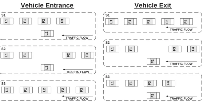
1.2 The three steps of the removal (split) and insertion (merge) of a vehicle in the platoon. . . 6
1.3 Distronic Adaptive Cruise Control in a Mercedes-Benz [Mercedes-Benz, 2004]. . . 9
1.4 ITS architecture of the ASHRA association [AHSRA, 2004]. . . 10
2.1 The general model of an agent interacting with the environment through sensors and effectors, from Russell and Norvig[2003]. . . 23
2.2 Reasoning process of a BDI agent, fromWooldridge [1999]. . . 25
2.3 Typical structure of a Multiagent System, fromJennings[2000]. . . 28
2.4 Roles involved in a team of attack helicopters, fromTambe [1997]. . . . 33
2.5 Domain level team operators in an example of the attack helicopter do-main fromTambe and Zhang [2000]. . . 35
2.6 Decision tree with probability and rewards for communicative acts in STEAM [Tambe and Zhang, 2000]. . . 37
3.1 Screen shot of a merging vehicle inside the HESTIA 3D simulator. . . . 40
3.2 The simulator’s engine main loop flow. . . 41
3.3 The general model of the vehicle simulation environment. . . 43
3.4 Abstract model of a car driveline dynamics. . . 46
3.5 Wheel slip calculation using Burckhardt method. . . 48
3.6 Tire side slip angle calculation using the single-track model. . . 49
3.7 Class diagram based on the auto21.object.vehicle package, which repre-sents the vehicle objects and their dynamics simulation classes. . . 53
3.8 UML Class diagram of the simulator’s sensors model. . . 56
3.9 UML Class diagram of the simulator’s communication model. . . 59
3.10 Class diagram of the Auto21 driver infrastructure for agents. . . 61
3.11 Abstracted model of the driving scenarios and log creation systems. . . 63
4.1 Architecture used for the PATH project in Howell et al.[2004]. . . 71
x
4.3 Intelligent Sensing sub-layer: detail. . . . 76
4.4 Vehicle Control sub-layer: detail. . . . 78
4.5 A global view at the Auto21 architecture’s design model. . . 82
4.6 Overview of the data structure and listener types in the Auto21 Intelli-gent Sensing sub-layer. . . . 84
4.7 Overview of the relation between the different components of the Vehicle Control sub-layer. . . . 86
4.8 The components relating to the Planning sub-layer, inside the architec-ture’s hierarchy. . . 87
4.9 Model of the vehicle’s desired velocity using a MPCC controller. . . 94
4.10 Model of the Belief Desire Intention (BDI) agent oriented Planning sub-layer. . . 97
5.1 Centralized decision making using a Traffic Control layer. . . . 103
5.2 Decentralized decision making using mobile agents. . . 105
5.3 Vehicle state transitions handled by the intra-platoon coordination. . . 106
5.4 Four coordination models of the merge and split manoeuvres. . . 107
5.5 Split task team’s role organization. . . 114
5.6 Platoon team operators tree. . . 115
5.7 The three steps of the removal (split) and insertion (merge) of a vehicle in the platoon. . . 117
6.1 Class diagram of the possible JACK Agent deriving from a common abstract agent skeleton. . . 122
6.2 AUML agent diagram of the JACK follower agent (AgJackFollower). . . 123
6.3 Agents’ identifications for the merge example. . . 124
6.4 AUML Level 2 state diagram of the merge protocol. . . . 125
6.5 AUML Level 2 protocol diagram of the merge protocol. . . . 126
6.6 AUML Level 3 state diagram of the merge protocol focusing on the merger’s follower agent (Gap Creator role). . . 127
6.7 AUML Level 3 state diagram of the merge protocol focusing on the leader agent. . . 127
6.8 AUML Level 3 state diagram of the merge protocol focusing on the merger agent. . . 128
6.9 JACK components’ relationships inside an Auto21 driving agent. . . 129
6.10 JACK capabilities usage by both the follower and leader agents. . . 131
6.11 Running loop of the JACK planning system. . . 132
6.12 JACK oriented beliefs structures and respective Cursors for planning usage. . . 134
6.13 Class diagram of the main Java and JACK classes related to inter-vehicle communications. . . 137
xi
6.14 Statechart diagram for the agents’ possible driving modes. . . 141 6.15 Activity diagram representing the transition occurring during an
emer-gency event. . . 143 6.16 The three steps of the removal (split) and insertion (merge) of a vehicle
in the platoon. . . 144 6.17 Classes and tasks involved in the creation of virtual vehicles. . . 145 6.18 Model of the main classes involved in the team-oriented infrastructure. 147 6.19 Diagram describing activities relating to each belief structure class in the
scenario of shared belief states. . . 150 6.20 Noisy merge test scenario through the six main platoon states. . . 154 6.21 Vehicles’ velocity in a noisy merge scenario using the centralized model. 156 6.22 Vehicles’ velocity in a noisy merge scenario using the teamwork model. 157 6.23 Vehicles’ acceleration in a noisy merge using the centralized model. . . 157 6.24 Vehicles’ acceleration in a noisy merge using the teamwork model. . . . 158 6.25 Inter-vehicle time distances in a noisy merge scenario using the
central-ized model. . . 158 6.26 Inter-vehicle time distances in a noisy merge scenario using the teamwork
model. . . 159 6.27 Difference with the inter-vehicle time distances and the safe distance, in
a noisy merge scenario using the centralized model. . . 160 6.28 Difference with the inter-vehicle time distances and the safe distance, in
a noisy merge scenario using the teamwork model. . . 160 6.29 Difference with the inter-vehicle time distances and the safe distance of
the merging vehicle, in two merge scenarios using the centralized model. 161 6.30 Difference with the inter-vehicle time distances and the safe distance of
the merging vehicle, in two merge scenarios using the teamwork model. 162 6.31 Difference with the inter-vehicle time distances and the safe distance of
the merging vehicle, in three merge scenarios using different coordination models. . . 163 6.32 Difference with the inter-vehicle time distances and the safe distance of
the splitting vehicle, in three split scenarios using different coordination models. . . 164
List of Algorithms
1 BDI-interpreter . . . . 26
2 function Guide-Time-Gap(kb, interV ehicleT ime) . . . . 93
Chapter 1
Introduction
During the past decades the amount of vehicles driven on North America’s major cities’ road system has increased at such a rate that we can not keep up by always adding more lanes to our highways [Randall et al.,2000]. Indeed, it is expected that the demand on America’s roadways will double by the year 2020 [Network, 2004], meaning that this increase in road users will bring along more pollution, accidents, stress, waste of time. Although the number of accidents are slowly decreasing with the increasing number of drivers in Canada [Gutoskie, 2001], it is estimated that more than 90% of all driving accidents are caused by human errors such as fatigue, inattention, or intoxicated driving [Smiley and Brookhuis, 1987]. Apart from having to face these problems, tomorrow’s Canadian driver is always trying to keep up with time by talking on the phone, putting on her makeup or reading while driving, and thus, could use some help to drive his or her car. An answer to our twenty-first century driver’s prayers could then be found in a new technology, gaining popularity all over the world, known as Intelligent Transportation Systems (ITS). These systems can be seen as a complex set of technologies that are derived from information and computer technologies, as well as applied to transport infrastructure and vehicles [Lin and Leung, 2002].
It is shown that ITS may provide potential capacity improvements as high as 20 percent [Stough, 2001], which would also lead to fewer pollution caused by both the reduction of time the vehicles spend on the highway and a low emission intelligent driving model based on smooth speed and acceleration changes [Barth, 1997]. Other benefits of ITS include: (i) increased safety; (ii) time savings; (iii) reliable transportation system; (iv) enhanced productivity for the domain of transportation [Gillen et al.,2000], etc. However, in order to benefit the most from ITS, all the technologies must be used as whole and they should collaborate to gain maximum efficiency.
Chapter 1. Introduction 2
At the moment, ITS is being used as part automated controllers in luxury vehicles including Intelligent Cruise Control (ICC)1 and warning or collision avoidance systems. Other services relating to the road infrastructures are also being offered in the form of communicated information relating to maps, service locators or anti-theft systems. In addition, the communication systems relating to ITS are also being improved radically through research, on the road infrastructure and vehicle level, to create information net-works through a dynamic intranet based on moving vehicles. Following the same path, the Canadian government is now looking for a newer approach to its transportation system, which would include more and more ITS technologies [ITS, 1999].
Being aware of all those facts, we propose to use all the current technologies re-lating to communicated traffic information and automated vehicle controllers inside a Collaborative Driving System (CDS)2 A CDS is a system, based on inter-vehicle com-munications, in which vehicles collaborate by exchanging information or request, in order to drive autonomously (more or less) in formations of vehicles. Thus, CDS is the ultimate form of ITS where the driver can be removed at some point and it is also a logical achievement of all the services offered by the ITS.
In this thesis we describe the research process that led us to the elaboration of a CDS prototype for the Auto21 project. This first chapter begins with a detailed representation of the problems we addressed (Section1.1). The following sections depict the reasons that motivate us to address a problem relating the Intelligent Transportation Systems (Section1.2) and the reasons that motivate the development of a Collaborative Driving System (Section 1.3). Finally, the objectives of this thesis are described in Section1.4, followed by a presentation of the thesis organization in Section 1.5.
1.1
Problem Description
Out of all the technological equipments people use in their every day life, the automobile is probably the most complex one. Indeed, technological advances available for vehi-cles are growing rapidly, often helping to reduce the negative effects of transportation systems, such as pollution, traffic and safety. Among the technologies making vehicles “intelligent”, the ones relating to driver’s assistance or autonomous driving are very complex issues. This type of system has to respond to real time critical situations as car malfunctions or cars suddenly braking in front of you. As more driving tasks are
1Also known as Adaptive Cruise Control (ACC), ICC uses sensors to automatically maintain
fol-lowing distances.
Chapter 1. Introduction 3
being handled by the vehicle itself, and more gadgets are appearing in your car, two problems arise: conflicts between these automated tasks and the human driver’s accep-tance or disturbance from these technologies. For example, automated route finders, using a digital map and a Global Positioning System (GPS), often have disturbing ef-fects on most drivers that cannot always stay focused on both the map and the road. Therefore, making a vehicle more “intelligent” by adding new technologies is one thing, but making the vehicle easier to drive for a human is another, which results in a prob-lem that can be addressed through a system incorporating all these technologies, like the CDS.
As many countries are battling in the race for autonomous vehicles, Canada is covering many aspects through the Auto21 network. This network and the definition of the project covering the autonomous vehicles aspects are described in Section1.1.1. Following this description, the problem of autonomous driving systems is presented in Section1.1.2. Then, the problems concerning the current ITS technologies are detailed in Section 1.1.3, while the difficulties in choosing the right test environment for our CDS are presented in Section1.1.4.
1.1.1
Auto21 Project
The Canadian government through the Canadian Networks of Centres of Excellence (NCE)3 and the help of more than 120 industry, government and institutional partners supports a network called Auto21 [Auto21,2004] [DAMAS-Auto21,2004], which brings together most of the Canadian researcher relating to the automobile domain. As its main goal, this networks aims to strengthen the competitive position of Canada in the automotive industry, our most important industry. The Network currently supports over 230 researchers working at more than 35 academic institutions, government re-search facilities and private sector rere-search labs across Canada and around the world. The researches on Collaborative Driving System (CDS) are done within the network as part of one of the six themes which is called Intelligent Systems and Sensors [Auto21, 2004]. The CDS project is led by Dr. Fran¸cois Michaud4 and involves the University of Sherbrooke, Calgary and Laval University. As its main goal, this project aims at creat-ing the prototype of a system allowcreat-ing vehicles to coordinate in high-density highway traffic (CDS presented in Section 1.3). To do so, each university has different fields of expertise that are required to complete this multi-disciplinary application and which are briefly described here:
3For more information, visithttp://www.nce.gc.ca
Chapter 1. Introduction 4
• The University of Calgary, being specialized in the field of telematics with the
de-partment of Geomatics engineering, has been assigned the research on Intelligent
Sensors for Vehicle Perception and Navigation.
• Laval University, through Dialog, Automatic Learning and Multiagent Systems
(DAMAS)5 Laboratory, is involved in the Coordination and Communication
Ar-chitectures sub-project that is detailed in this thesis.
• Sherbrooke University, through the Research Laboratory on Mobile Robotics and
Intelligent Systems (LABORIUS)6, is involved in the two previous sub-project as well as the Integrated Navigation, Guidance and Control sub-project.
1.1.2
Autonomous Driving
The previous section described the Auto21 research project that focuses on the col-laborative driving research domain, which aims at creating automated vehicles which collaborate in order to navigate through traffic. In this sort of driving, one generally form a platoon, which is a group of vehicles whose actions on the road are coordinated using communications. The first vehicle of a platoon is called the platoon leader and its role is to manage the platoon and guide it on the road at an undefined level of author-ity. The other vehicles are called followers and their main goal is to maintain a specific distance in time with the preceding vehicle using information from sensor(s). Figure1.1 shows a real platoon of vehicles formed of automated vehicles from the PATH project7, evolving on an Automated Highway System (AHS). Within the previously defined Auto21 project, different levels of system functionality have been defined to extend the project through time and needs. As it is the basic need of this project, all the different levels need to support and maintain a platoon structure during such events as vehicle leaving or entering their platoon through different possible emergencies. Three levels of autonomy specify the leader and the followers’ tasks and roles inside our project:
• In the first level of autonomy (autonomous longitudinal control), only the relative
distance and velocity of the cars are actively controlled in a type of generalized and distributed “cruise control system”, although drivers still steer their vehicles manually. A possible usage of the system at this level could be achieved using a driver assistance interface providing steering actions orders to the driver as a lane changes for example. This way, the system could control the vehicle’s brake and gas as long as the vehicle is part of, or switching from different platoons.
5For more information, visithttp://www.damas.ift.ulaval.ca
6For more information, visithttp://www.gel.usherb.ca/laborius/
Chapter 1. Introduction 5
• In the second level of autonomy (semi-autonomous longitudinal-lateral control),
the lateral and longitudinal motion of each vehicle are autonomously controlled relatively to the one preceding it, all the way to the first “lead car”, in a form of generalized car-train with a specially equipped lead car and trained driver. Again, a possible immediate use of the second level could be done using such lead cars that would co-exist in a given urban center, each with its own generic destination, much like a conventional train or bus, but with the added freedom of “getting off the train with your car”.
• Finally, in the third level of autonomy (fully autonomous longitudinal-lateral
con-trol), the addition of cooperative steering, using the road and the telematic infras-tructure as a guide for absolute motion control, will provide autonomous road-following capabilities. Thus, each vehicle in the third autonomy is able to take the role of a leader, meaning that platoons are completely and autonomously manage-able. This final level complicates the problem of coordination, as we eliminate the master entity called the leader, which centralized the coordination for a platoon formation. On the other hand, giving autonomy over collaborative issues to each vehicle allows for much more flexibility, which is crucial for platoons evolving in dense traffic.
Figure 1.1: Platoon of automated vehicles on an Automated Highway System, developed by the PATH project [Hedrick et al., 1994].
At the moment only the first level has been developed and represents the research described in this thesis. The various achievement levels that were just mentioned guar-antee that a functional system will be available at every step of this long-term project. To achieve this, the different functional systems should also evolve through software simulation, simulation with robots and finally, using real vehicles on a test road.
Chapter 1. Introduction 6
For a better understanding of the problems that must be resolved to maintain a stable platoon formation, the two main disturbances in the platoon formations are described below. Those two “disturbance”, called split (vehicle exiting the platoon) and merge (vehicle entering the platoon), are represented in Figure 1.2 and can be detailed as follows: S3 S2 S1 L1 F1 F2 F3 L2 L1 F1 F2 F3 L2 L1 F1 L2 F2 F3 S1 S2 S3 L1 F1 F3 F4 F2 L1 F1 F3 F4 F2 L1 F1 F2F2 F3 F4
Vehicle Entrance
Vehicle Exit
TRAFFIC FLOW
TRAFFIC FLOW
TRAFFIC FLOW TRAFFIC FLOW
TRAFFIC FLOW TRAFFIC FLOW
Figure 1.2: The three steps of the removal (split) and insertion (merge) of a vehicle in the platoon.
A Vehicle splitting happens when a vehicle member of a platoon decides to leave it,
thereby forming two non-empty platoons. To execute this manoeuvre, the splitter (F2 in Figure 1.2) must communicate its intention of leaving the platoon, so the platoon formation modifies the distances at the front and rear of the splitting vehicle as shown in
step 1 (S1 ) of Figure1.2. When this new formation gains stability, the splitting vehicle
F2 can change lane, while the rest of the platoon followers keep the same distances.
When the splitting vehicle safely left the platoon (S2 ), the gap created for its departure can be closed, thus forming back the precedent platoon, minus one vehicle (S3 ).
A Vehicle merging is the exact opposite of a split manoeuvre: two non-empty
pla-toons merge together to become one. This manoeuvre requires a platoon formed of only one vehicle, which is L2 in Figure1.2, to communicate to another platoon its will to join it. Moving from S1 to S2, the latter platoon reacts by creating a safe space and communicating to the merging vehicle the dynamic position of this space in its platoon. The merging vehicle modifies its velocity to join the meeting point, verifies if it is safe to merge and changes lane to enter the platoon formation and leave S2 to go to S3. Once the merged vehicle has stabilized its inter-vehicle distance, the platoon can reach its precedent formation plus one vehicle, by diminishing the distances with the new
Chapter 1. Introduction 7
vehicle. Although, the steps of the merge manoeuvre may differ from one coordination approach to another, this represents the general pattern of the merge manoeuvre.
Within the CDS project of Auto21, the problem of platoon driving within the three levels of autonomy presented above has been separated in three different sub-projects. Each sub-project has a common goal of creating a CDS that supports platoons of autonomous vehicles, but they attack very particular aspects of this problem.
• Intelligent Sensors for Vehicle Perception and Navigation is a sub-project that
studies different types of sensors to provide a higher level of information on the vehicles’ surrounding environment. To do so, optimal sets of sensors have to be developed and tested on vehicles. Algorithms for data fusion and filtering should also be developed considering the information required by the deliberative system. The information that the navigation system should provide includes: detection of obstacles, detection of neighboring cars, measurement of relative motion, absolute positioning, etc.
• Integrated Navigation, Guidance and Control sub-project has to develop a system
in charge of determining the desired dynamical state of the vehicle and applying actions relating to lateral and longitudinal motion in order to acquire those states. At a lower level, this project has to develop controllers, for both the steering wheel and gas and brake pedals, that act in collaboration with the guidance system, using low-level data from the sensors. For the guidance system, such things as the platoon configuration, vehicle’s destination and safety issues are taken into account to specify the desired vehicle states to the controllers. The guidance algorithms also need to resolve problems as the platoon’s string stability and focus on the robustness of this driving architecture.
• Coordination and Communication Architectures is the third sub-project, working
in relation with the navigation system by using the information it provides on the vehicle’s environment in order to reason about collaborative driving issues in a platoon configuration. By coordinating its vehicle’s actions, the communication architecture advises the guidance system, developed in the previous sub-project. The main coordination aspects that are handled are: the support of a vehicle’s entrance and exit from the platoon, a vehicle’s lane changes and entrance or exit from the highway, and the maintenance of stability with other vehicles member of the same platoon.
The first two sub-projects mainly concern the university of Sherbrooke and Calgary, while the last sub-project relates to the research detailed in this thesis.
Chapter 1. Introduction 8
1.1.3
Intelligent Transportation Systems & Artificial
Intelli-gence
As the name Intelligent Transport Systems invokes it, these systems must provide AI-based responses to their users. Although this should be true, most of the Intelligent Transportation Systems (ITS) technologies we have seen so far are based on reactive systems. This type of system does not reason or deliberate using exhaustive planning with up to date knowledge bases and elaborate communications, so their actions are very limited.
ITS have mostly focused on the reactive control aspects of automated vehicles, but very few research has been done on the cooperation and coordination of these tasks. In fact, at the vehicle level, Artificial Intelligence (AI) has mostly been used for applica-tions relating to longitudinal control such as Adaptive Cruise Control [Winner et al., 1996] and its enhanced versions, like the Semi-Autonomous Adaptive Cruise Control (SAACC) [Rajamani and Zhu,2002] detailed in Section4.1. On the other hand, the ve-hicle’s lateral control is a research area for which applicable solutions have only started to emerge and some have been successful in experimental conditions [Rajamani et al., 2000]. But this technology has to succeed in many more test scenarios since the two dimension control environment is much more complex than the one dimensions of the longitudinal control. In addition, the lane change control algorithms will require severe logical checks to ensure its functionality in uncertain situations. For this reason, auto-mated lateral control, as lane following will not be applicable to commercialized cars in the years to come, so we do not address this problem in our research.
Apart from lower-level control functions, much more complex applications have also been developed for the platoon architectures and were used in real life situations. Such a demonstration was done during Demo 2000 in Japan, by car constructors and projects as the University of California at Berkeley’s PATH project [Hedrick et al., 1994] and Japanese research programs as ASHRA8 andTsugawa et al. [2001]. Although the com-municative and guidance approaches presented in those projects proved to be successful, they did not address the problem of the vehicle formation’s flexibility and their com-munications’ efficiency as important issues. As a result, their coordination models have mostly been using communication protocols based on hard coded platoon states, instead of generic states that would be able to respond to any situation. From the informa-tion that these projects made available, their architecture is centered on the platoon, seen as a static formation and, most of the time, on its leader, thus restricting the
8For more information on Japan’s Advanced Cruise-Assist Highway System Research Association,
Chapter 1. Introduction 9
collaboration possibilities. Moreover, their collaboration models were kept simple and required scripted plans to react to unforeseen situations. To conclude these remarks, it must be mentioned that most of the national projects as the American and Japanese ones presented the fully autonomous platoon architecture as the highlight of their re-spective project [PATH, 2004], using a demo version developed at the beginning of the project, which was then left aside. Hence, for the past years, researchers concentrated their efforts on the longitudinal and lateral control to be used as intelligent cruise con-trol and left enormous amount of work for the collaborative/networking part of their architecture.
As it has been shown, the problem of longitudinal control is well defined and solu-tions are now being applied to luxury vehicles as some Mercedes-Benz models, shown in Figure 1.3, which is now available with a distronic adaptive cruise control capable of maintaining inter-vehicle distances. But a great amount of research has yet to be achieved to combine these vehicle control systems with the available route planning systems, in the most efficient manner. As it is represented in Figure 1.4, ITS infras-tructures offer multiple services that are very complex and require more coordination among them. Following from these facts, a “merging” system incorporating both the vehicle control and traffic information systems, through a Multiagent approach, seems inevitable. Accordingly, the problem of modelling a Collaborative Driving System as a Multiagent System (MAS), focusing on inter-vehicle coordination, was defined as the most propitious problem to address as part of this thesis and for the Auto21 project’s research at DAMAS laboratory.
Figure 1.3: Distronic Adaptive Cruise Control in a Mercedes-Benz [Mercedes-Benz, 2004].
Chapter 1. Introduction 10
Figure 1.4: ITS architecture of the ASHRA association [AHSRA, 2004].
1.1.4
Intelligent Transportation Systems Simulation
The last problem to be addressed as part of this thesis is the one of finding a suitable environment to test our autonomous driving system. As possible test environments, the following options can be considered: (i) a group of real vehicles; (ii) mobile robots; (iii) or a simulation software. Real vehicles have the advantage of representing the real environment in which the system will evolve and thus, being a good proof of the system feasibility. On the other hand, real vehicles are very expensive, they must be used on a dedicated highway and they may be harmful to people, depending on the type of tests that are executed. Mobile robots are also expensive and, as it is the case for real vehicles, they must be equipped with the necessary sensors and communication devices, which may also be very expensive.
On the other hand, a software simulator does not have the previous disadvantages, although it never reaches the same level of reliability as real vehicles. A software simulator is easier to use, since it does not require a dedicated space, expensive resources and people to manoeuvre, and it can be used in a running loop on customizable time frames. However, intelligent vehicles software simulators may be expensive and require expensive computers, depending on the level of detail of the vehicle model and the scale of the traffic simulation.
Chapter 1. Introduction 11
1.2
Motivations relating to Intelligent
Transporta-tion Systems
ITS have been introduced to the domain of transportation as an answer to many prob-lems that they are already starting to resolve. Indeed, this technology has been very useful in such aspects as: (a) traffic on highways; (b) safety while driving; (c) effects of vehicle on the environment; (d) efficiency in transportation industries; (e) and different social aspects relating to drivers. As these are probably the most important consider-ations relating to vehicle transportation, their enhancement through ITS constitutes a major motivation to the development of a Collaborative Driving System.
1.2.1
Traffic
As it was mentioned in this chapter’s introduction, the vehicle traffic on roads is a major problem that can be resolved using ITS. Up until now, the only solution was to build more roads, and from 1990 to 1995, the overall road system length has increased by more than 13,000 kilometers in Canada [Randall et al., 2000]. Furthermore, the highways formed of more than three lanes, which constitute the type of road usually extended to increase traffic capacity in major cities, grew by almost seven percent (even more for the United States and Mexico) in only five years [Randall et al.,2000]. Taking these facts into account, it is obvious that Canada has an urgent need for an alternative solution to its traffic problems.
As mentioned earlier, ITS have a proven capacity to improve traffic flow, and this is especially true when using technologies as the Adaptive Cruise Control (ACC) and the platoon model. Considering the fact that the instability in the traffic flow is the first cause of the usual traffic jams, stabilizing the traffic flow using ACC within a platoon will ultimately improve the highways capacity [Liang and Peng, 2000]. In-deed, studies on the platoon string stability using inter-vehicle communications showed a great improvement in the flow of vehicles that were used in platoon formations [Darbha and Rajagopal, 1998]. Moreover, using a dedicated highway for automated vehicles, the traffic equilibrium can be reached and maintained more easily at the high-way level, increasing even more the benefits of this technology. Apart from the traffic stability the capacity of existing highways can also be increased using this form of au-tomated driving. This can be done by reducing distances between vehicles until they reach the minimal safe distance, considering the controllers’ capabilities and the road condition.
Chapter 1. Introduction 12
1.2.2
Safety
Safety being a very important issue, it is a great incentive to improve automated driv-ing tasks and vehicle emergencies systems, which are directly linked to our CDS. Al-though Canada’s fatality rate per 10,000 motor vehicles registered decreased from 1.79 in 1996 to 1.63 during 1998, its international ranking among Organization for Economic Co-operation and Development (OECD) member countries decreased to 9th from 8th during 1996 and 1997, according toGutoskie[2001]. According to the same author, the national target calls for a 30% decrease in the average number of road users killed and seriously injured for the 10 years to come.
These numbers show that actions must be taken and automated driving systems could be very effective in resolving this problem. Indeed, technologies precursive to CDS, as the Collision Warning Systems (CWS) have improved the driver’s reaction time to emergencies and thus, lowered accidents. It has been argued that if an extra half a second of warning time, is provided to a driver, 60% of collisions can be avoided and with one second of warning time this portion increases to 90% [Woll, 1997]. Thus an important amount of collisions could be avoided using CDS, as this system’s sen-sors are directly linked to the effectors and have a faster reaction time to warnings than humans. Moreover, Touran et al.[1999] showed that the probability of a rear-end collision between a lead car and a car equipped with Autonomous Intelligent Cruise Control (AICC) is significantly lower compared to unequipped cars.
Finally, if we consider the arguments on the string stability, presented in the latter Section 1.2.1, safety enhancement can also be derived from the same facts. Hence, a stable vehicle formation lowers the acceleration and deceleration of each vehicle, thus lowering the possibility of collisions, often caused by unstable traffic flow leading the drivers to apply high decelerations.
1.2.3
Environment
Another major societal issue relating to the use of automobiles is its environment pacts. Following from new Canadian regulations, the automobile industry had to im-prove the negative impacts of their vehicles, but there are still a lot of efforts left to be done. Indeed, the automobile remains a major source of pollutants as the Cana-dian emissions of CO2, and contributes to increasing the concerns of global warming [Smith, 1993]. The Transportation sector (excluding pipelines) represents one of the largest sources of emissions in Canada, accounting for 24.7% of total emissions in 2001
Chapter 1. Introduction 13
(177 Mt) [Jaques, 2003]. For Canada’s major cities as Vancouver, Calgary, Toronto, Ottawa, Montreal, and Quebec City, cars have a very important influence on the air quality which influences the citizens’ well-being.
Liang and Peng[2000] proved that an Adaptive Cruise Control (ACC) could reduce the average acceleration level of a vehicle, which in return lowers the vehicle fuel con-sumptions and emissions. Furthermore,Bose and Ioannou [2001] showed that as much as 60% reduction in the air pollution could be achieved, if 10% of the current vehicles would be equipped with ACC. Because vehicles part of a CDS can easily maintain a stable velocity, as well as a close distance with their preceding vehicle, they can reduce the wind resistance applied on their vehicle. Therefore, platoon members have lower fuel consumptions, which is another important factor motivating the use of CDS.
1.2.4
Efficiency
By enhancing highways capacity and providing optimal route planning, ITS traffic man-agement systems can greatly improve the efficiency of Canada’s road network. This kind of benefit results from the operational efficiency gained by larger organizations making a wide use of the road network. Thus, city or national bus transit, freight transporta-tion companies, emergency vehicles and many more could profit from advances in ITS, at the productivity level. For both users relating to carriers and state agencies, there is a positive impact on the productivity when using ITS related to guidance or traf-fic management systems, as they provide signitraf-ficant cost savings and improved service [Proper, 1999].
In particular, ITS technologies relating to vehicle location systems have great impact on fleet management based on a vast road network. As shown in Gillen et al. [2000], Automatic Vehicle Location (AVL) applied to public transit allows transit managers to better utilize resources and generate cost savings. In addition, vehicle navigation devices, when deployed in a wider area, can greatly improve travel time, a well as travel planning time, as opposed to the use of standard maps [Inman et al., 1996]. At last, preliminary analysis revealed that the throughput generated using AHS was increased of 300% for autonomous driving vehicles in platoon formations, and 200% for non-platooned vehicles. Moreover, analysis based on freeways in Long Island and Washington DC, predicted that these capacity improvements could reduce travel time by 38% to 48% [Stevens, 1995]. AHS and the different navigation technologies relating to ITS thus have tremendous impact on the economy and this fact is enhanced when using CDS to form platoons.
Chapter 1. Introduction 14
1.2.5
Social Aspects
Social issues represent aspects of driving that may not be as obvious as the previous points, but that still need to be improved. Road rage is a rising problem, broadly publicized lately, which is usually caused by stressed drivers or unrespectful driving behaviour from other drivers. In fact, impaired driving and road rage constitute the most important anti-social behaviours and they even seem to be on the rise [Elliott, 1999]. In addition to the current societal problems, the drivers’ possible distractions are growing since the appearance multimedia technologies available in cars. These technologies, along with cellular phones, are now broadly used and they constitute a major cause of risky driving behaviours’ growth [Beirness et al., 2002].
As a solution to these problems, using an automated driving system can reduce the driver’s mental workload to a certain degree [Stanton and Young, 1998], which should improve the driver’s behaviour while driving. As the driver gets used to the system, a greater predictability and smoothness of the vehicle handling reduces, in most cases, the driver’s stress. As stress should be reduced and distracting technologies should affect less drivers with automated driving vehicles, anti-social driving behaviours would decrease. Moreover, using a fully automated driving system, the problems of impaired driving would be history, considering that humans would not have to drive anymore.
1.3
Motivations relating to Collaborative Driving
System
The motivation for the development of a Collaborative Driving System comes in part from the previous motivations of ITS, but also from the benefits surrounding the de-velopment of such a system. Canada has far more to go to meet the advances, in the domain of intelligent vehicles, that some countries as the USA and Japan have reached. In addition, ITS infrastructures are now being developed across the nation and the Collaborative Driving System (CDS) proposed in this thesis would constitute their smartest and most efficient use. A collaborative system embracing the currently available vehicle controllers would resolve the previous problem of conflicts between the different vehicles’ automation systems. Such a system would ultimately lead to a fully autonomously driven vehicle which would also resolve problems relating to the human driver’s acceptance, currently being studied.
Chapter 1. Introduction 15
our work inside the sub-project of Coordination and Communication Architectures. Our work first results in an application that can be reused for other similar problems, which is a great source of motivation, as shown in Section1.3.1. Another source of motivation is based on the communication and cooperation infrastructure that will be developed as part of our CDS, as explained in Section 1.3.2. A final motivation for this project is presented in Section 1.3.3, which describes the motivation in building our own software simulator.
1.3.1
Possible Deriving Applications
Within the CDS described in this thesis, the problem of maintaining a stable platoon of automated cars on the highway is being resolved. However, the methodology that is used to resolve this problem may also resolve similar problems part of different domains. In fact, various dynamic systems that evolve in a transportation related environment share several needs and goals, and could also be automated at a certain degree, as we plan to do with cars. Girard et al. [2001] presented four similar applications of networked multi-vehicle systems: (1) Mobile Offshore Base (MOB); (2) Automotive Applications (AA) using platooning strategies; (3) Unmanned Combat Air Vehicles (UCAV); (4) Autonomous Underwater Vehicles (AUV). As these applications all relate to the control of a certain group of vehicles equipped with sensors and effectors, that communicate to coordinate their actions, they can share a common agent-based generic architecture. Thus, considering that abstract manoeuvring and communication behaviours can be shared among these applications, it is possible to share a common application core.
If we focus on the domain of automobile, many applications, using a CDS to form platoons, can be outlined. In the public sector, CDS can be used for public transit as the PATH project has done using platoons of buses. Then, emergency vehicles could also find great improvements in their efficiency, as automated driving would enable them to get prepared or perform rescue tasks while driving. As mentioned in Section 1.2.4, freight transportation companies would be more efficient by regrouping their trucks in platoon formations using automated guidance systems. Other derived applications could be developed, as for example, the use of CDS in small electric vehicles, within retirement villages where elders, which often suffer from different disabilities, could be moved around more easily. Moreover, an autonomous driving vehicle could also be used by rental cars companies or for valet parking services, since the unmanned vehicles could return back to a specific destination autonomously. Finally, different applications relating to militaries are foreseen. For instance, the creation of unmanned military convoys transporting goods during dangerous missions could be based on a CDS and it would result in no human losses.
Chapter 1. Introduction 16
1.3.2
Communication and Cooperation in ITS
As mentioned in Section 1.1.3, recent advances in ITS are starting to build a commu-nication infrastructure dedicated to vehicle guidance and traffic management. Private companies are also part of this technologic boom, as new models for communication networks using vehicles are being proposed by companies like Nortel and Siemens. Ma-jor car manufacturers are using more and more communication devices in their vehicles and have plans, in association with telecommunication corporations, for vehicle-oriented Wireless Local Area Network (WLAN) [Holfelder, 2003]. Thus, as the communication structure is being built, information from road-side sensors are also starting to be ex-changed for navigation and traffic management purposes.
Furthermore, vehicles should also take part in this network by both sending informa-tion about their state and inteninforma-tions, and receiving the same informainforma-tion from others, in order to plan driving actions. Communication among vehicles using CDS or ACC is very profitable for automated driving in formation of many vehicles. Swaroop et al. [1994] demonstrated that a constant spacing platoon is stable only if certain types of vehicle-to-vehicle communication are available. Xu et al.[2002] also shown the benefits of communication as an addition to standard ACC, which resulted in faster response time and a smoother and safer reaction, resulting in a more comfortable ride.
Most of the result on the use of inter-vehicle communications related to cruise control technologies and not much to complex guidance and control systems as the CDS. Using complex communication messages, control and guidance systems could communicate information about their driving actions through protocols relating to intra or inter-platoon tasks. A convenient system model in which we could include the inter-vehicle guidance and coordination issues could be the Multiagent System (MAS). Indeed, agent based transport logistics systems have been used to analyze the data provided by road-based sensors, and they proved to be useful in representing and managing traffic information [Davidsson et al., 2004]. MAS have also been used in the domain of transportation for applications such as real-time traffic lights control and presented much more efficient results [Dresner and Stone, 2004], and in some cases safer results [Conde et al., 2004], than the current reactive systems.
Wada et al. [2004] have shown that for their prototype of autonomous vehicle, one of the major requirement was for the vehicle to support additional resources without administrative overhead and to offer in-vehicle networks that are flexible and scalable. This relates to what was mentioned in Section 1.1.3 about the current ITS flexibility needs which could be resolved through a Multiagent System. Such system provides a wrapping layer over the multiple sensing and actuating technologies as well as
interop-Chapter 1. Introduction 17
erability through the Agent Communication Language (ACL). This type of wrapper is detailed in Chapter2, which presents different agent-based architectures along with agent-based coordination techniques. These techniques have been used in many en-vironments, to handle distributed autonomous applications, as it is the case for our platoon of vehicles. As some examples, we can point out successful uses of a MAS that motivate its use in our CDS:
• Agents for industrial systems management, as the ARCHON project which led to
many applications as a power distribution system in Spain [Jennings et al.,1995].
• Agents for spacecraft control consisting in a real-time in-flight diagnosis
applica-tion [Georgeff and Lansky,1987].
• Frigates resource management and positioning in a real-time combat environment,
as the NEREUS project [Morissette et al.,2004].
• Management of different rescue teams acting in a large simulated urban disaster,
to save lives and minimize building damages [Paquet et al., 2004].
• Multi Agent Based Simulation used to synthesize social behaviours of humans or
any dynamic objects [Moss and Davidsson, 2001].
• Agents for workflow and business process management as the ADEPT system
[Jennings et al., 1996].
• Tactical air traffic controller agents that help alleviate air traffic congestion, as
the OASIS system [Ljungberg and Lucas,1992].
1.3.3
Collaborative Driving System Simulation
As mentioned in Section1.1.4, considering the different complications relating to the use of real cars or robots to test our CDS, it was more advisable to use a software vehicle simulator, at least for the initial phases of development. The choice of a software simulator was motivated by the following aspects, which also drove our choice for the right simulator: (a) a low cost; (b) reasonable computing power needs; (c) reliability; (d) respond to our ITS needs; (e) easy to use and extend; (f) able to interface with the Java language. More specifically, the chosen software simulator had to support the following requirements, relating to CDS: (i) simulate the vehicle dynamics with a complete vehicle model (with a certain degree of details); (ii) simulate internal and external vehicle sensors; (iii) simulate different types of inter-vehicle communication systems; (iv) simulate manageable vehicle models; (v) manage platoon scenarios in
Chapter 1. Introduction 18
batch testing with possible uncertain events; (vi) keep a simulation log on vehicle and driving agents aspects.
Given those needs, the two main possibilities are to either build our own simulator or buy one. Building its own simulator requires more time and software simulation knowledge, but gives total control over the simulator’s source code. In fact, a CDS simulator can be built over an existing open source simulator project or using available libraries, and this can reduce the programming task. On the other hand, if there is a simulator available on the market, that exactly suits your needs, it may be the best option. Thus, considering that we had software developer resources available at the DAMAS laboratory, it was more advisable to either choose a simulator we could easily extend or to build our own simulator.
As a first glance at the available simulators relating to autonomous vehicles, we looked at simulators from two similar projects: California PATH’s Smart AHS Simula-tor [Kourjanski et al., 1998] and Carnegie Mellon’s Simulated Highways for Intelligent Vehicle Algorithms (SHIVA) [Sukthankar et al., 1998]. PATH’s simulator answers to most of our requirements as it was built to test autonomous vehicle platoon formations, but it was programmed using a new language called SHIFT and it requires Silicon Graphics supercomputers. SHIVA simulator was programmed in C++, which can be easily interfaced with Java, but it requires Sun Sparc Stations to run, it has a poor documentation and it does not offer licensing possibilities with source code access. Other free vehicle simulators and some open source ones are also available through the Internet, but most of them are either too abstract or oriented for gaming purposes. Detailed vehicle simulators, like CarSim9, are also available, but usually at expensive cost and they cannot be extended for the autonomous driving implementation needs, since their source code is not available. Finally, we also analyzed traffic simulators that mainly simulate vehicles at a higher level, like the microscopic traffic simulation pack-age Paramics, developed by Quadstone10. Similar simulators that can simulate road network’s through a social network at a very high macro-level of traffic representation are available [Balmer et al., 2004], but all of them suit traffic management needs, so they were not considered in our final choice.
Considering all these options, we concluded that the best choice was to build our own in simulator using some available libraries to lower the programming task. Using Java programming language and its variety of free libraries and open source code, we knew that our simulator could easily interface with our driving agents, also programmed in Java. Therefore, the choice of building our own Java-based simulator responded to
9For more information, visithttp://www.carsim.com
Chapter 1. Introduction 19
our motivations in having a simulation software that respects our specific needs, with total control over the source code.
1.4
Thesis Objectives
According to the Auto21 project’s initial tasks decomposition for the theme F:
Intel-ligent Systems and Sensors [Auto21, 2004], different milestones have been established
and divided within working groups according to research specialization and university affiliation. The Collaborative Driving Systems project’s objectives have been briefly summarized in these lines:
This research project aims at developing a prototype of Collaborative Driving System (CDS) that can be used as part of a Canadian Automated Highway System (AHS). The objectives of this research should be to pro-vide a recommendation and description for an intelligent navigation, guid-ance and cooperation system. The description of the different architectures should be merged together into one fully operative CDS that should be fault tolerant, efficient and robust, while focusing on safety. The CDS prototype should be developed and tested using software simulation, robots and vehi-cles to validate the system’s motivations that were presented in Section 1.2 and more importantly, demonstrate the system’s robustness. As presented in Section 1.1.2, the first model should be an answer to the vehicle’s longi-tudinal control in a model relating to an Adaptive Cruise Control (ACC) system, used in a platoon formation.
Furthermore, the sub-project assigned to DAMAS (Coordination and Communication
Architectures) has been defined as follows:
This project has to conduct a survey about potential architectures in-corporating the main components of the CDS (sensing, control and com-munication) as one system that can be used in each vehicle, to cooperate with the highway’s infrastructures. Within this architecture, the research should focus on the usage of communication systems and possible coordi-nation techniques. In a first phase, this project should resolve the prob-lem of coordination inside a same platoon (intra-platoon) and in second phase, between neighboring platoons (inter-platoon). The coordination sys-tem should demonstrate its ability to handle events such as lane changes and
Chapter 1. Introduction 20
vehicle merging and leaving platoons, and it should maintain the platoon stable through different possible disturbances. As part of our objectives, the complexity of the approaches, the ability to handle unanticipated event and the amount (in quantity and from/to whom) of communication required to reach an efficient level of coordination are examined.
Accordingly, the objective of our research project mainly consists in studying different architectures related to automated transport systems and the coordination of agents. This study should then lead to the conception of a MAS suiting most of our needs, and to the conception of a simulated system to prove our affirmations. The tasks required to meet these objectives can be summarized in the following points:
• Study different architectures and techniques used for automated vehicles.
• Design a flexible architecture, specific to this project, suiting the different
sub-projects needs: Perception and Navigation, Guidance and Control, Coordination
and Communication.
• Analyze and develop coordination techniques within the previous architecture, to
point out the pros and cons of each one.
• Design and develop the selected coordination technique(s) into a collaborative
driving application, where agents guide the vehicles to respond to the platooning problematic.
• Analyze and design a highway simulator with specific vehicle technology
require-ments, to test and evaluate the developed Collaborative Driving System (CDS).
• Implement and develop the previous simulator, according to gradual simulation
needs.
• Analyze the coordination and communication aspects of the platooning
manoeu-vres under various simulated scenarios and conclude on the performances of the proposed CDS.
Although a fully autonomous platoon architecture may seem out of reach, consider-ing the current available technology, a gradual application of the collaboratconsider-ing system, as presented in the problematic is feasible. Hence, even though the lateral controllers are not currently applicable to commercialized vehicles, our coordination model will be usable by assigning tasks that cannot be safely automated, directly to the human driver. Using an interface between the driver and the CDS, as a communication system through the vehicle’s speakers, the CDS could request tasks as change lane to the driver. This way, the inter-vehicle tasks coordinated through our system could be applied, at
Chapter 1. Introduction 21
any time within the development phases, by either using an automated controller or the human driver, for different vehicle control issues. Accordingly, to set the basis of our CDS, we decided to focus on developing a functional demo supporting the automated platoon formation. Since we aim to study approaches for collaborative driving, this research project mostly focuses on the collaboration between platoon members.
As mentioned earlier, the leading vehicle also includes sensing and communication devices, but it is driven by a human for the initial phase. Thus, every platoon members, including the leader, are considered as agents, which can sense and communicate with each others. The only difference between those agents is the actions they can perform, as the leader only communicates, while the followers can also control the gas and brake pedals, and later, the steering wheel.
1.5
Thesis Organization
This thesis is organized in such a way that agent and Multiagent general architec-tures are first presented in Chapter 2, along with different Multiagent coordination techniques, by putting the emphasis on Teamwork for agents. Before describing the MAS we developed for Auto21, the simulation environment in which our driving agents evolve is presented in Chapter3, which details every modules of our simulator and how this simulator supports the test scenarios presented as part of our results. Afterwards, Chapter4presents the architecture we developed for the Collaborative Driving System of Auto21 and details the coordination and control aspects, as well as the implementa-tion process of this architecture. The inter and intra-platoon coordinaimplementa-tion models that enable our vehicles to collaborate are then described in Chapter 5, which focuses on centralized and teamwork intra-platoon coordination models. Finally, the development of our agents inside our simulator, according to the previous architecture, is explained in Chapter6, which also focuses on the centralized and teamwork coordination models. This chapter ends with a presentation and a discussion on the simulation results relat-ing to intra-platoon coordination test scenarios. To conclude, Chapter 7 summarizes our different achievements and results, and ends by detailing possible future works for the CDS project of Auto21.
Chapter 2
Agents and Muliagent Systems
From its debut, around 1943 [Russell and Norvig,2003], Artificial Intelligence (AI) has been a leading research area of computer science, which proposes a rational approach to realize a given task. In order to use techniques relating to AI in different environments and provide a reasoning system closer to the “human” model, the agent paradigm has widely been used in the past decades. The term “agent” has been used for many purpose and may be a little confusing at that point. For this reason, this chapter clarifies the different possible architectures of agents that relate to different types of environment and levels of complexity. A given environment has specific properties that can be seen as a level of challenge for an agent. If the environment in which our agent evolves forces it to reason about its goals before acting, a deliberative architecture should be considered. In simpler environments, a reactive architecture is more appropriate, while other environments may necessitate reactive and deliberative behavior, thus requiring a hybrid agent architecture. Finally, in other types of environment, an agent must interact with other agents in order to collaborate or compete for a given goal. In this context, the term Multiagent System (MAS) is used to qualify a system in which distributed agents must interact with each others. In this thesis, a MAS is used to model the automated driving system installed on each vehicle to autonomously drive a vehicle and collaborate with others.
This chapter does not propose a vast introduction to intelligent agents, since this subject has been covered many times, so the reader should refer toRussell and Norvig [2003] for a complete introduction. Instead, only the agent and MAS aspects relating to our Collaborative Driving System (CDS) and autonomous driving agents are covered in the following sections. First, Section 2.1 describes the agent paradigm and presents the major architectures that can be used to develop an agent. Then, Section 2.2 de-scribes the problems that are addressed by a Multiagent System and presents different
Chapter 2. Agents and Muliagent Systems 23
architectures that can used to coordinate agents.
2.1
Single Agent Architectures
An agent is usually described as anything that can perceive its environment through sen-sors and act upon that environment through effectors (actuators) [Russell and Norvig, 2003]. Another definition given by Wooldridge [2002] formally and briefly defines an agent as a computer system that is situated in some environment, and that is capable of autonomous action in this environment in order to meet its design objectives. More applicatively, an agent is an autonomous entity that is usually goal driven, meaning that all of its actions will be done in accordance with a specific goal, pursued by the agent. The actions applied by the agent are therefore a response to a percept or a sequence of percept that defines the agent’s view of its environment.
The general representation of an agent is shown in Figure 2.1, where the question mark represents the agent’s reasoning system. The reasoning system defines the agent’s rationality, which in turn defines the agent’s autonomy. At the lowest level of auton-omy, an agent mainly relies on its built-in knowledge, while at the highest level, the agent’s experience (beliefs acquired through time) is also determining on its behaviour. These different levels of autonomy can be acquired through different categories of agent architectures, going from a simple reactive agent to a complex deliberative agent. The following sections present those architectures, starting with the simple reflex (purely reactive) agent in Section 2.1.1, followed by the deliberative agent (agent with states) in Section 2.1.2 and the Belief Desire Intention (BDI) agent in Section2.1.3.
Figure 2.1: The general model of an agent interacting with the environment through sensors and effectors, from Russell and Norvig [2003].
![Figure 1.1: Platoon of automated vehicles on an Automated Highway System, developed by the PATH project [Hedrick et al., 1994].](https://thumb-eu.123doks.com/thumbv2/123doknet/3439172.100474/17.892.230.728.639.935/figure-platoon-automated-vehicles-automated-highway-developed-hedrick.webp)
![Figure 2.1: The general model of an agent interacting with the environment through sensors and effectors, from Russell and Norvig [2003].](https://thumb-eu.123doks.com/thumbv2/123doknet/3439172.100474/35.892.279.683.830.1059/figure-general-interacting-environment-sensors-effectors-russell-norvig.webp)
![Figure 2.4: Roles involved in a team of attack helicopters, from Tambe [1997].](https://thumb-eu.123doks.com/thumbv2/123doknet/3439172.100474/45.892.211.753.873.1067/figure-roles-involved-team-attack-helicopters-tambe.webp)
![Figure 2.5: Domain level team operators in an example of the attack helicopter domain from Tambe and Zhang [2000].](https://thumb-eu.123doks.com/thumbv2/123doknet/3439172.100474/47.892.187.777.509.731/figure-domain-operators-example-attack-helicopter-domain-tambe.webp)
![Figure 2.6 shows a decision tree representing the Selective Communication (SC) decision the agent must take, as part of the STEAM framework [Tambe and Zhang, 2000]](https://thumb-eu.123doks.com/thumbv2/123doknet/3439172.100474/49.892.320.647.551.862/figure-decision-representing-selective-communication-decision-steam-framework.webp)


![Figure 4.1: Architecture used for the PATH project in Howell et al. [2004].](https://thumb-eu.123doks.com/thumbv2/123doknet/3439172.100474/83.892.340.641.247.693/figure-architecture-used-path-project-howell-et-al.webp)