O
pen
A
rchive
T
OULOUSE
A
rchive
O
uverte (
OATAO
)
OATAO is an open access repository that collects the work of Toulouse researchers and
makes it freely available over the web where possible.
This is an author-deposited version published in : http://oatao.univ-toulouse.fr/
Eprints ID : 6643
To link to this document :
DOI:10.1039/C0LC00058BURL :
http://dx.doi.org/10.1039/C0LC00058BTo cite this version :
Lorber, Nicolasand Sarrazin, Flavieand Guillot, Pierreand Panizza, Pascaland Colin, Annieand Pavageau,Bertrandand Hany, Cindyand Maestro, Patrickand Marre, Samueland Delclos, Thomasand Aymonier, Cyriland Subra, Pascaleand Prat, Laurentand Gourdon, Christopheand Mignard,
EmmanuelSome recent advances in the design and the use of miniaturized droplet-based continuous process: Applications in chemistry and high-pressure microflows.(2011) Lab on a Chip, vol. 11 (n° 5). pp. 779-787. ISSN
1473-0197
Any correspondance concerning this service should be sent to the repository
administrator: [email protected]
.Some Recent Advances in the Design and the Use of
Miniaturized Droplet-Based Continuous Process:
Applications of Millifluidics in Chemistry and
Implementation of Supercritical Fluids in Microfluidics
Nicolas Lorber,a Flavie Sarrazin,a Pierre Guillot,a Pascal Panizza,b Annie Colin,a Bertrand Pavageau,a Cindy Hany,a Patrick Maestro,a Samuel Marre,c Thomas Delclos,c Cyril Aymonnier,c Pascale Subra,d Laurent Prat,e Christophe Gourdon,e Emmanuel Mignarda,*
a
CNRS-Rhodia-Université Bordeaux 1 UMR5258 Laboratoire du Futur, 178 Av. Dr. Albert Schweitzer, 33608 Pessac Cedex, France
b
CNRS-Université de Rennes 1 UMR6626 Groupe Matière Condensée et Matériaux, Campus de Beaulieu, 35000 Rennes, France
c
CNRS UPR 9048 ICMCB, 87 Avenue du Dr. A. Schweitzer, F-33608, Pessac Cedex, France
d
CNRS-ENSAM-ENSCPB-Université Bordeaux 1 UMR 8508 TREFLE, 16 Avenue Pey Berland, 33607 Pessac Cedex, France
e
CNRS UMR 5503 Laboratoire de Génie Chimique, Site de Labège BP 84234 Campus INP-ENSIACET 4 allée Emile Monso 31432 Toulouse cedex 4
Summary
This mini-review focuses on some advanced researches done at the laboratory. We aim at two different approaches. One describes the use of droplets in chemistry as individual batch microreactors flowing within a millifluidic tool. This is an inexpensive, versatile and easy to use approach which was upscaled from the microfluidics. It allows producing hierarchically organized multiple emulsion or particles with a good control of the size and shape, as well as providing a convenient data acquisition platform. Hence, droplet-based millifluidics was used with success to perform in line monitoring of very slow to rather fast chemical reactions, i.e., from hours to few minutes. The other approach describes the use of fluids at high pressure and various temperatures in transparent microfluidic systems. The main technical challenge was to demonstrate the possibility to generate stable droplets and reversible dripping to jetting transitions at microscale from supercritical carbon dioxide-liquid water microcoflows. We have found some discrepancies between our data and the predicted results obtained with a model based on immiscible liq.-liq. coflows. Further works are in progress in the laboratory to understand the behavior of immiscible SCF-liq. coflows and to improve the model. Since, we used this strategy to produce with success microparticles by using supercritical antisolvent process. To our point of view, this supercritical microfluidic tool is a promising approach to develop more sustainable processes in chemistry.
Keywords: millifluidics, chemistry in droplets, supercritical fluids, high throughput screening
This mini-review is divided into two parts and discusses the use in chemistry of droplets or jets obtained (1) in millifluidic devices or (2) in high-pressure resistant devices, i.e., typically above the critical pressure of carbon dioxide (7.38 MPa). We define the scale of the millifluidic tools to be between 500µm and few millimetres, i.e., typically less than 3 mm. About the high-pressure resistant devices, we consider only transparent ones and not those based on metallic or other opaque materials. Thus, we will not discuss about standard microfluidic systems which have a scale length below 500µm and that are not designed to be used with supercritical fluids. This approach is well-covered by high ranked reviews.1
The Millifluidic tool
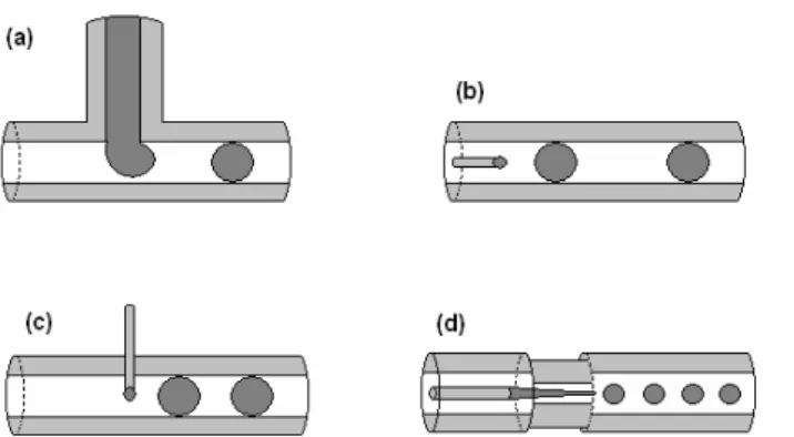
Unlike microfluidics, one can literally play with tubing and fittings to set up a millifluidic device in few minutes on a laboratory bench. Indeed, this technological approach does not need the use of expensive microfabrication equipments in a clean room. Several materials are commercially available: for instance, different grade of Teflon, glass, or fused silica tubes. According to the chemistry which will be used within the millifluidic tubing one can easily choose between hydrophilic and hydrophobic surfaces. Furthermore, world-wide suppliers like Upchurch sell any length of tubing with a large choice of (sub)millimetric inner diameters with tolerances less than 5%. Versatile nuts and sleeves allow using from 360 µm to 1/16 or 1/8 in. OD tubing within the same device. Thus, by correctly choosing inner and outer diameters of these tubes, one can assemble them with inexpensive commercial tees or crosses and design flow-focusing or simple T junction patterns as in microfluidics (cf. Figure 1). Although length characteristics are one or two orders higher than that one used in microfluidics, Reynolds numbers are still low, i.e., about 1, and flows are thus laminar. Capillary numbers are also low, i.e., about 10-3 meaning that one can easily generate droplets in a rough millifluidic device.
Since raw materials are easily available one can disassemble partially or totally the system, if plugged or to modify the flow pathway. One can also decide to recycle part of the materials after a first use of the device. This convenient versatility of this technological approach is one of the main advantages of millifluidics vs microfluidics. Indeed, microfluidics is based on expensive microfabrication technologies which require a high know-how and expertise,2 although millifluidics does not require any time consuming and expensive soft lithography or etching techniques for their fabrication. Moreover, more the microchannel pathway is complex and more the risk of failure in realizing the microchip could be important. This is a time and money consuming process which can be avoided by using millifluidics (if possible).
Figure 1. Different schemes of capillary-based millifluidic devices for the generation of droplets: T junction
device (a); coflow device (b); cross-flow device (c); flow-focusing device.
Another advantage consists in the transparency of these tubes. It allows using nonintrusive optical or analytical systems trough the walls.3 For instance, by coupling a CCD to the millifluidic device, one can
1 Marre, S.; Jensen, K.F. Chem. Soc. Rev., 39 (2010) 183-1202; Huebner, A.; Sharma, S.; Srisa-Art, M.; Hollfelder, F.; Edel, J. B.; DeMello, A. J. Lab Chip 2008, 8, 1244-1254; Song, H.; Chen, D. L.; Ismagilov, R. F. Angew. Chem. Int. Ed. 2006, 45, 7336-7356. 2
Madou, M.J. Fundamentals of Microfabrication: The Science of Miniaturization, second edition, Taylor & Francis, Inc., 2002. 3
observe jetting to dripping transitions, traffic of droplets, mixing between two miscible fluids, etc.4,5 These observations are of prime interest in order to understand and control basic hydrodynamic processes. They will allow using small droplets as microreactors in chemistry. Moreover, mounting an analytical system like a spectrometer above the flow pathway allows acquiring basic data to monitor the chemistry. This mini-review will describe in more details this advantage latter.
First, if one wants to use droplets to perform chemical reaction, it is important to know how to produce them, how to manage them on a network. In the following part we will discuss these two points.
Dripping to jetting transition in millifluidics
The following applications require the control of the production of droplets. In this section, we point out the parameters in charge of droplets or jet production. Since the seminal works of Plateau and Rayleigh, i.e., for more than a century, it is well known that in viscid cylindrical jets in air are unstable to disturbances of wavelength larger than the jet circumference. The interplay of interfacial stresses and inertial forces that rules jet breakup is rather complex, and can be rationalized in terms of absolute and convective instabilities as determined from a linear analysis. An absolute instability corresponds to disturbances growing and propagating both downstream and upstream, leading after a transient to drops released at or close to the injection nozzle. Increasing velocity sufficiently can make the instability convective with perturbations that propagate downstream while they grow, allowing for a continuous fluid thread to persist. Several experimental studies support this picture. Same mechanisms are in charge of the droplets production in millifluidic devices.
In our work, we propose a quantitative analysis of the droplet or jet production mechanisms.6,7 We discuss the role of experimental parameters such as surface tension, flow rates, viscosity. To reach this goal, we have first performed quantitative experiments in cylindrical geometries. In our experiments, we generate a jet in a cylindrical glass capillary of inner radius Rc, using as a nozzle a glass capillary of square cross-section with a tapered end. The outer dimension of this square capillary is very close to the inner diameter of the cylindrical tube which ensures good alignment and centering. Rc is in the 200-500 µm range, whereas the radius of the tapered orifice of the square tube is set between 20 and 50 µm using a pipette-puller set up. Syringe pumps are used to inject an inner fluid of viscosity hi at a rate Qi in the square capillary and the outer fluid of viscosity ηe at a rate Qe through the cylindrical capillary. This leads to coaxial injection at the tapered orifice. We observe flow patterns which vary significantly with operational (Qe, Qi), geometrical (Rc), and system parameters (ηi, ηe, surface tension γ). Figure 2 displays the typical outcome of an experiment. A droplet regime is found for low Qi, with either droplets emitted periodically right at the nozzle—symbol (open circle)—or non spherical pluglike droplets resulting from the instability of an emerging oscillating jet (filled gray circle). Jets are found in the bottom right corner of Figure 2 with different visual aspects: wavy jets with features that are convected downstream (open square), and for larger values of Qi, straight jets (filled square) that persist throughout the cylindrical capillary. For large values of the external flow rate Qe, we observe what we call jetting: thin and rather straight jets (open diamond) that extend over some distance in the capillary tube before.
4
Engl, W. MS Thesis, University of Borddeaux, France, 2006 5
Sarrazin, F. MS Thesis, Institut National Polytechnique de Toulouse, France, 2006
6 Stability of a Jet in Confined Pressure-Driven Biphasic Flows at Low Reynolds Numbers . P. Guillot, A. Colin, A. S. Utada, and A. Ajdari — Phys. Rev. Lett. 99, 104502 (2007)
7 Stability of a jet in confined pressure-driven biphasic flows at low Reynolds number in various geometries . P. Guillot, A. Colin, A. Ajdari — Phys. Rev. E 78 (2008) 107807
Figure 2: Flow diagram. The internal fluid is a mixture of water and glycerine with a viscosity equal to 55
mPa.s. The external fluid is a silicone oil with a viscosity equal to 235 mPa.s. The open circles correspond to drops, the filled circles to plugs, the open squares to wavy jets, the squares to jets, the diamond to jetting. Increasing the internal flow rate at a given external one induces the formation of a large jet stabilized by the walls. Increasing the external flow rate at a given internal one induces the formation of a jetting stabilized by the speed of the flow. The line is the theoretical model predicting the transition between absolute and convective instability. No adjustable parameters are required to calculate this line.
To capture this behavior, we have performed a linear analysis of the stability of the flow. We model these phenomena analytically, taking advantage of the simplicity and symmetry of the present cylindrical geometry. We describe the droplets –jet transition as the transition from convective to absolute instability. This simple linear analysis reaches remarkable agreement with the data. We note however that some disagreement with the model exist when the centering of the internal capillary tube is not properly done. This comprehensive study allows us to predict the domain of existence of droplets in the parameter plane (x,Ka) for a given viscosity ratio between the internal and the external fluid. x is the degree of confining and is equal to x=rio/Rc where rio is the radius of the unperturbed jet and Rc the radius of the external capillary tube.
Ka is a genuine capillary number equal to
γ
z oc
P
R
Ka
=
∂
2
. In short, droplets correspond to small capillary number Ka and small confinement ratio x, while plugs require larger values of x. At higher values of Ka, increasing the confinement ratio x shifts the behavior from ‘‘jetting’’ (with emission of droplets at a large finite distance from the nozzle) to stable jets. Small confinement ratio x, while plugs require larger values of x. At higher values of Ka, increasing the confinement ratio x shifts the behavior from ‘‘jetting’’ (with emission of droplets at a large finite distance from the nozzle) to stable jets.
Figure 3. Master curve in the plane Ka,x for a given ratio of viscosity between the internal viscosity and
external one.
Traffic of droplets in millifluidics
To sort droplets, one may use T junction. Let us consider a basic yet essential element of a droplet traffic motion, which is the effect of a T junction where the flow is separated into two streams8.
Our experiments shows that, when a train of droplets reach a T junction, the droplets are either distributed alternatively in the two arms or are all collected into the shortest one. This behavior is due to the hydrodynamic feedback of droplets in the different outlets on the selection process occurring at the junction. The droplets go into the arm where the global flow rate is the higher. At high dilution, this is equivalent to say the all the droplets go into the shortest arm. Increasing the number of droplets changes this point. This results in increasing the number of droplets in the shortest arm and thus in increasing its hydrodynamic resistance. As the global flow rate decreases in the shortest arm, the droplets go into the longest one. Obviously, this behavior leads to complex dynamical process, whereby a droplet arriving at a junction reacts to the instantaneous state of the system to ‘decide’ in which arm to go. Using this argument, a mean field model, yielding semi quantitative results, offers a first guide to predict droplet traffic in branched networks. By varying the external flow rate, we are able to manage the flow of droplets.
8
Droplet Traffic at a Simple Junction at Low Capillary Numbers, W. Engl, M. Roche, A. Colin, P. Panizza, and A. Ajdari. Physical Review Letters 95, (2005)
Figure 4. Droplets patterns in the arm of a T junction at various droplet concentrations. At low droplets
concentration, all the droplets go in the shortest arm. Increasing the droplet concentration promotes the repartition regime.
Mixing inside droplets
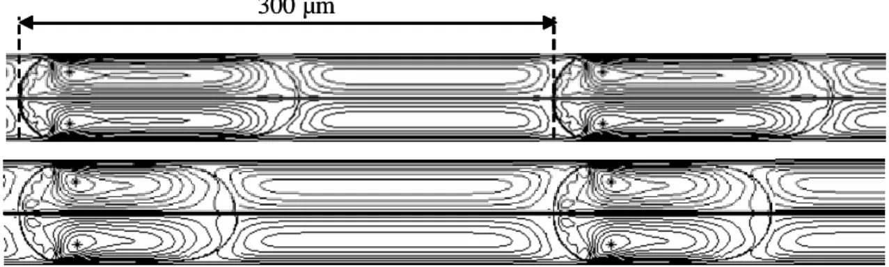
The droplets can be compared with nanoliter stirred batch reactors moving at constant speed. Indeed, when the droplets touch the channel edges, they benefit from natural convection, so that an inner convection loop takes place in each quarter of the droplet (cf. Figure 5).
300 µm
300 µm
Figure 5. Streamlines inside the droplets and the continous (simulations). Droplets have the same volume.
We can see the effect of the Capillary number on the shape of the interfaces: high Capillary number (top) and low Capillary number (down).
We performed numerical simulations of the hydrodynamics so as to get a better understanding of the mixing phenomena.9 Several studies in the literature focus on the simulation of two-phase flows inside milli- and microchannels.10,11 Our simulations combine the constraints of a strong viscosity ratio between the continuous and dispersed phases and 3D drop shape evolution. We use a finite-volume/front-capturing method which has been developed at the Fluids Mechanics Institute in Toulouse (IMFT) and allows to perform 2D and 3D simulations at a reasonable cost. The velocity field inside the droplets obtained by direct numerical simulations is compared to microparticle image velocimetry (micro-PIV) measurements and are in good agreement (cf. Figure 6). Furthermore, injecting a passive tracer in the simulated droplets reveals the existence of internal recirculation zones which could be problematic if a strong micromixing is needed.
9Sarrazin, F.; Bonometti, T.; Loubière, K.; Prat, L.; Gourdon, C.; Magnaudet,J. AIChE J. 2006, 5, 4061. 10
Holdych, D.J.; Georgiadis, J.G.; Buckius, R.O. Phys Fluids. 2004, 16, 1791. 11 Coulliette, C.; Pozrikidis, C. J Fluid Mech. 1998, 358, 1.
(a) -1 -0.5 0 0.5 1 -1 0 1 z U ' / U g simulations y = 0.04 (b) -1 -0.5 0 0.5 1 -1 0 1 y U ' / U g z = 0.04 z = 0.56 z = 0.69 z = 0.43
Figure 6. Velocity profiles obtained by simulations and micro PIV. Velocities U’ are measured in the
referential of the droplet at half droplet length, and normalized by droplet velocity Ug. (a) Profile in the vertical plane near the channel middle plane; (b) Profiles in several horizontal planes at different normalized height z.
As a result of this work, we showed that the time of one inner convection loop inside the droplet is four times bigger than the time that the droplet takes to cross its own length. Nevertheless, whereas this recirculation time is constant, the shape of the stream lines inside the droplet differs depending on the operating conditions.12 Simulating the interaction of the stream lines with a diffusive profile of a solute inside the droplet helps calculating the mixing time. For example, if the droplets contain two components, each one confined in a half-hemisphere symmetrically from the channel middle plane, the mixing is equivalent to a diffusive process ten times faster than pure diffusion. In first approximation, the mean diffusive length necessary to perform mixing is equal to a quarter width of the drop, distance between the product separation line and the node of the recirculation loop. This is illustrated in Figure 7 where an acid-based colour reaction is monitored thanks to a fast camera so as to follow the homogenisation of the droplets. x y z x y z
Figure 7. Experimental determination of the mixing time inside the droplets, thanks to an acid-base colour
reaction. Basic reagent contains bromothymol blue which bleaches when pH decreases.
As a conclusion, the mixing time inside droplets is strongly correlated to the channel size. In some cases, and more particularly when channel width approaches millimetre scales, the mixing time could be superior to one minute and droplet velocity and shape should be well-adapted to benefit from natural convection. Nevertheless, the mixing can also be enhanced by adapting the reagent orientation before the formation of the droplets,13 or the channel geometry (use of winding channels for example).14,15 When mixing time is not
12
Sarrazin, F.; Bonometti, T.; Prat, L.; Gourdon, C.; Magnaudet, J. Microfluidics and Nanofluidics, 2008, 5, 131. 13
Link, D.; Grasland-Mongrain, E.; Duri, A.; Sarrazin, F.; Cheng, Z.; Cristobal, G.; Marquez, M.; Weitz, D.A. Angew. Chem. Int. Ed., 45, 2556.
such a limiting parameter, millifluidics scale is very easy to handle, offers very good heat transfer performances and easy-sampling conditions.
Use of droplets in chemistry
There are many advantages to use small droplets as microreactors in chemistry. First, by using the same experimental conditions to generate these droplets, i.e., constant flow rates, flow patterns, etc., they will have the same size and shape, and will contain the same chemical composition. Hence, all microreactors at the outlet of the droplet generator will be identical; at least until flow rates remain the same. By varying flow rates from the feed stock solutions one can easily control the chemical composition of these microreactors. As far as there is no coalescence, each microreactor will have the same residence time within the millifluidic device, meaning that one can finely control this continuous process.
On the other hand, due to their small sizes and high surface-area-to-volume ratios, heat exchanges between the inner medium of the droplet with the continuous phase are favored. Thus, one can make chemical reactions with experimental conditions which could be difficult to use in conventional batch reactors, i.e., high concentrations or temperatures. For instance, we were able to control the free radical polymerization of acrylic acid at low pH from monomer concentrations as high as 40 % w/v at 98°C.16 In these conditions, a glass batch reactor commonly used at the laboratory would not allow controlling neither the heat removal nor the monitoring of such a polymerization reaction. Thus, this droplet-based millifluidic approach improves safety at the laboratory. Furthermore, one can use this miniaturized approach to study polymerizations from rare and expensive chemicals. Other key characteristics to this miniaturized droplet-based approach consist in the possibility to manage viscosity issues without plugging the channel. Indeed, lubrication by the carrier phase at the wall allows droplets to move along the tubes. This is particularly important since viscosity in polymerization reactions can increase to thousand of centipoises or even higher in the case of gel processes. Moreover, there is no residence time distribution. Indeed, on the contrary of single-phase flows, dispersion due to convection and diffusion is eliminated because the reactants are compartmentalized within droplets which cannot coalesce.
Synthesis
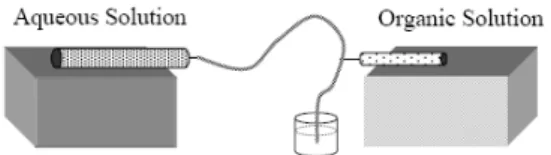
Droplet-based millifluidics was used with success over the past few years. For instance, D.T. McQuade et al. use a very simple approach to create fluid-filled spheres that are captured by interfacial polymerization as they are formed.17 This pioneer approach illustrates how a simpler and cheaper approach to microfluidics can allow generating micrometer-size particles as show in Figure 8.
Figure 8. Schematic of Fluidic Device from reference 17.
As illustrated in Figure 8, aqueous solution flows through poly(vinyl chloride) (PVC) tubing (1/16 in. i.d. and the organic solution is directly introduced in the middle of the channel via a 30-gauge needle inserted through the wall of the PVC tubing. Authors claimed this simple cross-flow design yields coaxial fluidic behavior similar to axisymmetric microfluidic devices, meaning that droplets are entirely surrounded by the carrier phase which facilitates the interfacial polymerization. This reaction is quite fast at room temperature since it involved a highly reactive acyl chloride solution to an immiscible aqueous solution containing polyethyleneimine which has a high number of amine functions. The capsules are thus quickly obtained and
14
Sarrazin, F.; Prat, L.; Di Miceli, N.; Link, D.; Cristobal, G.; D.A. Weitz, Chem. Eng. Sc.2007, 62, 1042. 15
Sarrazin, F.; Salmon, J.-B.; Servant, L. Anal. Chem., 2008, 80, 1689. 16
Lorber, N.; Pavageau, B.; Mignard, E. Macromolecules, under press.
exhibit an original fibrous structure but are not perfectly spherical. The effect of the continuous phase flow rate on capsule size was investigated, and as expected, by increasing this flow rate, the average size decreases. Gokmen et al. also used this simple approach to generate in situ water-in-oil High Internal-Phase Emulsion (HIPE) droplets.18 This water-in-oil-in-water (W/O/W) double emulsion was then solidified by photopolymerization of the mixture of acrylate or methacrylate comonomers. By this way, the authors fabricate highly porous material, i.e., poly(HIPE). Interestingly, due to the high viscosity of some of the HIPE formulations, a jetting regime was sometimes observed, meaning that in these cases non-spherical objects were thus obtained. This solidified HIPE beads or rods exhibit micropores with no “skin” effect, and the surface area was measured as high as 16 m2/g. These poly(HIPE) were hence functionalized by a “click”-“click” two-step modification process to introduced benzyltriazolyl moieties. To our point of view, this is a very interesting approach to fabricate functional polymeric supports, which could have numerous applications in catalysis or separation techniques. We currently look for synthesizing such lightweight functional materials in the laboratory.
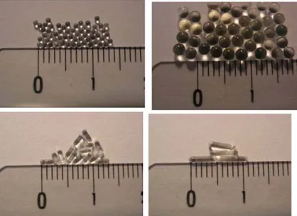
Figure 9. Example of tuned spherical and Rod-like particles fabricated after exposing monomer droplets of
a photocurable resist to UV radiation from reference 19. The scale is in centimetres.
In our laboratory, we demonstrated that droplet-based millifluidics is a powerful technique to continuously produce isometric particles. For instance, photopolymerization of the NOA 80 resin (Northland Optical Adhesive) yields polymeric beads in a size range from 100 to 2000µm with an extremely narrow distribution, i.e., less than 2% (Figure 9).19 These particle sizes were controlled by varying the flow rates of the continuous and disperse phases. Interestingly, shape can be easily controlled by tuning the constrained geometry of the millifluidic device, leading to the production of rods. Same methodology was applied in the synthesis of silica ceramics by sol–gel chemistry.20 Both SAXS and nitrogen physisorption measurements reveal that these low cost bead or rod ceramics are essentially microporous.
18
Gokmen, M. T.; Van Camp, W.; Colver, P. J.; Bon, S. A. F.; Du Prez, F.E. Macromolecules 2009, 42 9289-9294. 19
Engl, W.; Tachibana, M.; Panizza, P.;Backov, R. Int. J. Multiphase Flow 2007, 33, 897-903. 20
Tachibana, M.; Engl, W.; Panizza, P.; Deleuze, H.; Lecommandoux, S.; Ushiki, H.; Backov, R. Chem. Eng. Process. 2008, 47, 1317-1322.
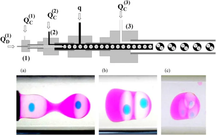
Figure 10. (Top) Device used to fabricate triple macro-emulsions. (Bottom) Images of various
fabricatedW/O/W/Omacro-emulsions from reference 21.
We also used this tool to produce hierarchically organized large emulsions and particles, still with a very good control of the size and shape (cf. Figure 10).21 Hence, we generatedstable multiple emulsions without the need of surfactants: double W/O/W or triple W/O/W/O macro-emulsions with internal droplets made from different chemical compositions. We solidified these particles by photopolymerization of the organic phases, thus obtaining spherical or non-spherical objects containing several liquid compartments.
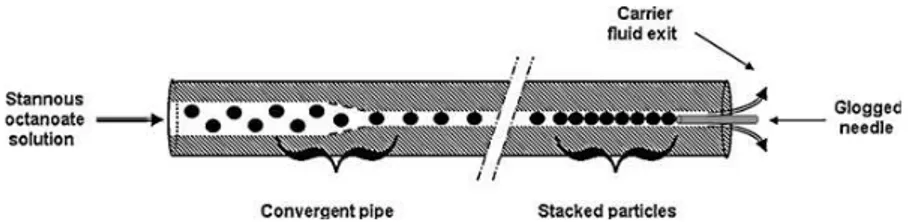
Other authors have investigated in more details the relationship between flow rate, viscosities and the inner diameter of a capillary used on the size of the obtained droplets.22 A simplified axisymmetric millifluidic device was used instead of a rough cross-flow capillary-based device. From this ingenious system, they described an empiric law which gives the droplet size as a function of the inner diameter of the capillary and the ratio of the capillary numbers between the continuous and dispersed phases with an exponent equal to -0.22. And by using this axisymmetric approach, the authors fabricated from micron to millimeter-sized monodisperse polymer beads. These rigid polymeric structures were obtained by photopolymerization of methyl methacrylates. These authors have also used millifluidic tubing constriction and a needle positioned directly in the axis of the Teflon tube in order to stack polymeric particles at the outlet (cf. Figure 11).23 Interestingly, the obstruction of the outlet allows producing a pearl necklace. However, this structure obtained by photoinitied polymerization of methyl methacrylates is brittle and no mechanical properties were measured. Nevertheless, by choosing more appropriate chemical composition, one can envision to synthesize pearl necklaces which interesting properties, i.e., from copolymeric beads as well as hybrids or Janus-like particles.
21
Panizza, P.; Engl, W.; Hany, C.; Backov, R. Colloids Surf. A: Physicochem. Eng. Aspects 2008, 312, 24-31. 22
Serra, C.; Berton, N.; Bouquey, M.; Prat, L.; Hadziioannou, G. Langmuir 2007, 23, 7745-7750. 23 Bouquey, M.; Serra, C.; Berton, N.; Prat, L.; Hadziioannou, G. Chem. Eng. J., 135S (2008) S93.
Figure 11: Schematic of particles stacking from reference 23.
Very recently, these authors have used commercial tubing and fittings in order to build a simplified flow-focusing millifluidic device.24 It consists in using a first capillary in a T junction and another identical one inside a line junction along the main axis (cf. Figure 12). The key characteristics of this system to generate small droplets are the size of the inner diameters and the space between the two capillaries. Although it could be difficult to line up and hold well aligned these rather soft capillaries, with this device the authors generated smaller droplets than with the previous system; down to 25 µm, thanks to a strong flow-focusing effect. The authors photopolymerized these small droplets flowing within a millimetric-sized Teflon tubes and hence obtained polymeric microbeads. They also make inorganic/polymer hybrids by feeding the dispersed phase with gold or ZnO nanoparticles.
Figure 12: Optical microscopy images of the axisymmetric capillary-based flow-focusing microfluidic
device and the stretching of the monomer phase thread at the entrance of the second capillary (inset) from reference 24.
Other groups have explored the synthesis of inorganic materials or have investigated basic operation in organic chemistry. For instance, G. Salazar-Alvarez et al. as well as A. A. Hassan et al. have obtained iron oxide nanoparticles with a narrow size distribution by using a simple T-junction device or a coaxial flow device respectively.25,26 Although Z. T. Cygan et al. fabricated thiolene-based devices instead of using Teflon tubes, they used with success this droplet-based approach in the bromination of alkenes inside benzene droplets.27 G. Guan et al. investigated transesterification of sunflower oil with methanol using a KOH catalyst in a rough droplet-based millifluidics. Interestingly the authors could monitor the Fatty Acid Methyl Esters (FAMEs) formation by observing the behaviour of the segmented coflow along the FEP tubing. As far as the reaction progressed the generated slug-flow disappears, leading to a homogeneous flow of FAMEs in 100s. This demonstrates that biodiesel can be efficiently produced with high yields in short reaction times by using droplet-based base millifluidics.
Data acquisition
Surprisingly, one of the main features of this droplet-based approach has not yet been much explored so far. Indeed, the consequence of using this droplet approach is there is an equivalence between the position of the
24
Chang, Z.; Serra C. A.; Bouquey, M.; Kraus, I.; Li S.; Köhler, J. M. Nanotechnology 21 (2010) 015605. 25
Salazar-alvarez, G.; Muhammed, M.; Zagorodni, A. A. Chem. Eng. Sci., 61 (2006) 4625-4633. 26
Hassan, A. A.; Sandre, O.; Cabuil, V.; Tabeling, P.; Chem. Commun., (2008) 1783-1785. 27 Cygan, Z. T.; Cabral, J. T.; Beers, K. L.; Amis, E. J. Langmuir 2005, 21, 3629-3634.
droplet within the channel and the time course of the reaction: i.e., according to the rate of the reaction, each droplet will have the same chemical composition when they reach the same position along the channel. This is of particular interest in order to acquire basic kinetic data. Indeed, by using the time-space equivalence and non-intrusive in line monitoring capacity due to the transparency of the walls of the channels, one can determine concentrations at any time of the reaction. For instance, K. L. Beers at al. used Raman spectroscopy in order to monitor benzyl methacrylate conversion. Droplets of various monomer compositions were generated by using a flow focusing technique, and then were photopolymerized in a thiolene-based millifluidic device.28 Recently at the laboratory, we used this specific feature in order to monitor slow kinetics of a redox reactionby using in line UV-visible spectroscopy.3 From this monitoring, we were hence able to extract both rate coefficients and orders of the formation of iodine from a mixture of potassium persulfate and potassium iodide solutions. Data obtained by the droplet-based millifluidic approach are in very good agreement with those obtained in a conventional batch reactor, and validated our methodology. Furthermore, this process eliminates the tedious sampling and handling like extraction, dilutions or filtrations, etc. that are required by monitoring based on HPLC or GC sequential injections for instance. Moreover, such chromatographic systems as well as nuclear magnetic resonance instruments are usually costly to implement and maintain. Thus, in line monitoring is a faster and eventually cheaper method than these ones in order to obtain concentrations in function of time. And kinetics of reactions which are done from few minutes to hours can be determined safely. Another advantage is that by using a non-destructive approach, one can recover the product at the outlet of the device for subsequent analyses.
At the laboratory, we used this in-line monitoring capacity in order to investigate safely acrylic acid (AA) polymerization in “extreme” experimental conditions.16,29,30 AA mixed with sodium persulfate at low pH was used as a fast and exothermic in situ thermal initiated polymerization model. First, the reaction mixture was confined into small droplets by using a capillary-based coflow device. Then, these droplets flowed within a FEP tube (1/16”in. ID) rolled up on a metallic cylinder. This metallic support facilitates to regulate the temperature of the reaction mixture. As can be seen in Figure 13, a window allows having an optical access for in line analysis. To this purpose, we have used a confocal Raman spectrometer. This feature allows using the time-space correspondence.
Figure 13. Picture of the main part of the droplet-based millifluidic device used at the laboratory.
After generating the droplets containing the reagents, and as soon as the equilibrium is reached, the Raman scattering spectrum of the initial diluted AA solution was recorded as a reference for the whole experiment (t0). As soon as the temperature set is reached, we started to record Raman spectra at different positions
along the device.
28 Barnes, S. E.; Cygan, Z. T.; Yates, J. K.; Beers, K. L.; Amis, E. J. Analyst 2006, 131, 1027-1033. 29
Lorber, N.; Pavageau, B.; Mignard, E. Macromol. Symp., under press. 30
WO2008043860 (2008), Rhodia operation, invs.: Pavageau, B.; Cristobal, G.; Rabih, R.; Vuong, C. T.; WO2008043922 (2008), Rhodia operation and University of Bordeaux 1, invs.: Panizza, P.; Cristobal, G.; Pavageau, B.;Colin, A.; FR2907030 (2008), Rhodia Recherches et Technologies and Université de Bordeaux 1, invs.: Panizza, P.; Engl, W.; Pavageau, B.; Galinat, S.
5000 1 104 1.5 104 2 104 2.5 104 1000 1100 1200 1300 1400 1500 1600
(a)
C o u n ts Raman shift (cm-1) # M I O M O O M O M O O M M M M 0 5000 1 104 1.5 104 2 104 2.5 104 1600 1620 1640 1660 1680 1700 (b) t0 10s 20s 30s 40s 50s 60s 70s 80s 90s 120s 180s 300s C o u n ts Raman shift (cm-1)Figure 14. (a) Typical Raman spectrum obtained during the experiment. Peaks are indexed according to the
contribution of chemicals (#: ref (KNO3); M: AA; I: Na2S2O8 and O: fluorinated oil). (b) Decrease of the
peak corresponding to the conversion of monomer in function of time.
During the experiment, constant flow rates were applied in order to set the residence time (trd) equal to the
total time of the polymerization, i.e., trd = Vtube/Qtotal , where Vtube is the volume of the tube which is actually
heated and Qtotal is equal to the sum of all applied flow rates. As far as the droplets flow along the heated
tubular reactor the polymerization occurs. Since the position x of a droplet within the tubular reactor corresponds to the time course of reaction (tx), thus each droplet reaching that position are identical in terms
of conversions. The relationship between the position and the time course of the reaction is: tx = (x . π . r
2
) / Qtotal, where r is the internal radius of the tube. Recording Raman spectra at different
positions along the tubular reactor leads to plot conversion (or concentrations) in function of time as shown in Figure 15. 0 0.2 0.4 0.6 0.8 1 0 500 1000 1500 2000 60°C pH 1.8 72°C pH 1.8 60°C pH 5.5 72°C pH 5.5 C o n v e rs io n Time (s) (a) -4.5 -4 -3.5 -3 -2.5 -2 -1.5 -1 0.00265 0.0027 0.00275 0.0028 0.00285 0.0029 0.00295 0.003 y = 13.8 - 5637.6x R2= 0.99035 ln R p ,0 1/T (°K-1) (b)
Figure 15. (a) Molar conversions of AA in function of time for several initial monomer concentrations
([I2]0 = 0.028 mol.L
-1
at pH 1.8 at 60°C and 72°C; and pH 5.5 at 60°C and 72°C). (b) Temperature
dependence of Rp,0 obtained at 40% w/v and pH 1.8. Only the filled circles were taken into account for the
linear fit.
( )
( )
( )
( )
( )
( )
( )
0 0 0 3 3 1 1 t h t h t h t h t n t n t KNO AA KNO AA AA AA = − − =ρ
(1)
where hy(t) is the height measured at a time t at the top of the peak corresponding to the chemical y. By
assuming concentration is directly proportional to the height of the peak and there is no significant change in the respective Raman spectra of the heated chemicals (i.e., shifting or band broadening), then these height ratios allowing to eliminate all calibration constants. The molar concentration of AA is thus: [AA]t = [AA]0 . [1-ρ(t)]. By using the law mass conservation one can calculate molar PAA concentrations in
function of time. As first approximations, we assume an ideal mixing and we have neglected any variation of the volume of the microreactors which occurs during the polymerization reaction due to the difference between the mass densities of the monomer and polymer.
Thanks to the versatility of the droplet-based millifluidics, it was easy to screen different experimental conditions, including those which could not be studied in conventional batch reactors (i.e., high monomer concentrations and temperatures; until 40 % w/v and 98°C). Indeed, in such experimental conditions the reaction is completed in less than one minute, hence less time than necessary to acquire one Raman spectra. By using droplet-based millifluidics one can safely measure the decrease of the AA concentration thanks to the time-space equivalence. Thus, the overall activation energy for polymerization rate was estimated to 47.0 kJ.mol-1.16 This is twice less the value expected when the polymerization reaction is initiated by the thermal dissociation of the initiator (about 90 kJ/mol).31 We hence assume that difference in temperature of reaction cause difference in solution viscosity, and the polymerization rate can dramatically decrease with the temperature. For instance, if one runs the experiment at low temperature, i.e., <60°C, or high monomer concentration, i.e., >25 % w/v, the solution become viscous enough to make the propagation step diffusion-limited due to diffusional limitations on the monomer. These results set the stage for further studies of polymerization reactions where detailed basic kinetic data must be acquired in conditions which cannot be investigated by using conventional batch glassware, i.e., high temperatures or concentrations. This versatile approach can also be used as an efficient High Throughput Screening tool. Indeed, one can easily change the internal droplet concentrations by adjusting the flow rates from the stock solutions. And then, as expected, the polymerization rate is slower at higher pH due to the decrease reactivity of ionized AA relative to the unionized monomer. Furthermore, at low or high pH polymerizations exhibited higher order with respect to monomer concentration than the usual first-order kinetics for ideal free-radical polymerization, and a ½ dependence with respect to the initiator concentration. Further works are in progress at the laboratory to investigate copolymerization reactions by using this approach and to generate more complex polymeric structures.
High pressure resistant micro- and millifluidics
One of the future challenges in micro- millifluidics consists in the development of transparent continuous process able to resist to high pressures and temperatures. In particular, the development of such pressure resistant miniaturized systems offers the opportunity to study and to observe SuperCritical Fluid (SCF)-liquid coflows.32 SCFs are of special interest since they exhibit some specific properties: they do not have surface tension, diffusion is more important than those of liquids (~10-3 cm2.s-1), and density is close to those of gas (from 10 to 100.10-6 Pa.s). The particular interest of using SCFs in microfluidics stands in the possibility to tune these physical properties over a wide range of values, by small changes of pressure and/or temperature, unlike for liquid systems.
31
Odian, G. In Principles of Polymerization, 4th ed.; ed. Odian, G., Ed.; John Wiley & Sons, Inc.: Hoboken, New Jersey, 2004. 32
(a) S. Marre, J. Park, J. Rempel, J. Guan, M.G. Bawendi, K.F. Jensen, Adv. Mater., 20(24), 4830 (2008), (b) F. Trachsel, B. Tidona, S. Desportes, Ph. Rudolf von Rohr, J. Supercrit. Fluids, 48, 146 (2009), (c) F. Benito-Lopez, R.M. Tigelaar, K. Salbut, J. Huskens, R.J.M. Egberink, D.N. Reinhoudt, H.J.G.E. Gardeniers, W. Verboom, Lab Chip, 7, 1345 (2007).
Few publications describe the use SCFs in such pressure resistant devices.33,34,35,36 Two different approaches were chosen, i.e., the use of low cost and easy to use technique based on silica capillary tubing37 or the more versatile but expensive and tedious microfabrication of glass-glass or Si-Pyrex microchips.33-35,38 Currently at the laboratory, we have chosen to use fused silica tubes in order to study SCF-liquid coflows.39 The main aim was first to demonstrate such a coflow allows generating jetting or dripping regimes in a controlled fashion, and then to use theses droplets or jet as microreactors.
We use supercritical carbon dioxide (scCO2)-liquid water as a model system. Indeed, scCO2 is of special
interest because of its low cost and its moderate critical conditions (Tc=31.1ºC, pc=7.38 MPa). Furthermore,
in this case, it is essentially immiscible with water in the range of temperature investigated in our works (20 to 80°C), although CO2 can be dissolved in water as a result of carbonate and hydrogencarbonate formation
(0.8 – 1.2 mol/L at pH = 7.7 for 20 < T < 80°C and 8 MPa < p < 12 MPa).40
Moreover, it is important to point out that these solvents are environmentally benign and biocompatible, nontoxic, cheap, abundant, volatile, inert, non-flammable and recyclable. And scCO2 is one of the few
solvents not regulated as a volatile organic solvents and compounds by the U.S. Environmental Protection Agency. Hence, the use of scCO2 as green solvent has been identified in 2005 by Ryoji Noyori as one of the
main important developments in green chemistry.41 All these advantages have driven the use of scCO2 in
chemistry and physics in order to synthesize new materials.42 And such a scCO2-water coflow in
miniaturized transparent continuous processes is hence promised to be developed further, at least at the laboratory scale.
Figure 16. Coflowing set-up developed at the laboratory, from reference 39. (a) Typical observation of the
scCO2-in-water coflow. (b) General set-up including two high pressure pumps, a T connector for the
insertion of the small silica tubing in the larger one, a temperature controlled area and a back pressure regulator.
33
F. Trachsel, B. Tidona, S. Desportes, Ph. Rudolf von Rohr, J. Supercrit. Fluids, 48, (2009) 146 ; A. Urakawa, F. Trachsel, PR von Rohr, A. Baiker, Analyst, 133, (2008) 1352.
34
S. Marre, J. Park, J. Rempel, J. Guan, MG. Bawendi, KF. Jensen, Adv. Mater., 20, (2008) 1. 35
F. Benito-Lopez, RM. Tiggelaar, K. Salbut, J. Huskens, RJM. Egberink, DN. Reinhoudt, HJGE. Gardeniers, W. Verboom, Lab
Chip, 7, (2007) 1345.
36
J. Kobayashi, Y. Mori, S. Kobayashi, Chem. Commun., (2005) 2567. 37
F. Benito-Lopez, W. Verboom, M. Kakuta, JHGE. Gardeniers, RJM. Egberink, ER. Oosterbroek, A. van den Bergb, DN. Reinhoudt, Chem. Commun., (2005) 2857.
38
RM. Tiggelaar, F. Benito-Lopez, DC. Hermesa, H. Rathgen, RJM. Egberink, FG. Mugele , DN. Reinhoudt, A. van den Berg, W. Verboom, HJGE. Gardeniers, Chemical Engineering Journal, 131 (2007) 163.
39
Marre, S.; Aymonier, C.; Subre, P.; Mignard E. Appl. Phys. Lett. 95 (2009) 134105. 40
S. Portier, C. Rochelle, Chem. Geo., 217, 187 (2005)
41
Noyori, R. Chemical Communications 2005, 1807. 42
(a) A. loppinet-Serani, C. Aymonier, F. Cansell, ChemSuschem, 1(6), 486 (2008), (b) F. Cansell and C. Aymonier, J. Supercrit.
In Figure 16 is shown the scheme of our capillary-based coflow system. From this set up, we have recently demonstrated the possibility to easily generate stable and reversible SCFs droplets or jets in immiscible liquids without the need of surfactant (cf. Figure 17). The dripping regime includes spherical droplets and slugs. Jets have been observed with various shapes: large straight jet, thin jets breaking into droplets, wavy jet, wavy jet breaking into slugs, thin straight jet or more complicated shapes for flows with high Reynolds numbers. Surface modification of the silica tubing with perfluoroalkyl trichlorosilane43 allows scCO2 to wet
the surface making possible to use the reverse system: i.e., liquid water in scCO2.
Figure 17. Dynamic phase diagram in the (Qin and Qout) plane of the scCO2-liquid water coflowing system,
from reference 39.
One of the advantages of scCO2 is that it is possible to vary its physical properties, i.e., density and
viscosity, with the pressure or temperature. We have shown that coordinates of the dripping to jetting transition vary significantly with experimental conditions (cf. Figure 18): for example, at fixed constant velocity, it is possible to switch from one flow type jet drops, only by varying the pressure, all other parameters remaining constant elsewhere. Moreover, we have also shown that one can tune reversibly the dynamic phase diagram simply by changing the pressure or the temperature, without neither changing flow rates, nor fluids in use.
Figure 18. Dynamic phase diagrams in the (Qin and Qout) plane of the scCO2-liq. water coflowing system
obtained at two different pressures, all other parameters being kept constant, from reference 39.
By using a model based on immiscible liq.-liq. coflow we were not able to fit the dripping to jetting transition.44 This is not surprising since in the case of this SCF-liq. coflow inertia forces must be taken into
43
U. Srinivasan, M.R. Houston, R.T. Howe, R. Maboudian, J. Microelectromechan. Syst., 7(2), 252 (1998). 44 P. Guillot, A. Colin, AS. Utada, A. Ajdari, Physic. Rev. Lett., 99, (2007) 104502.
account in such model.45 Indeed, due to the low viscosity of SCF very high Reynolds numbers (10 < Re < 3500) can be obtained. Further works are in progress in the laboratory to improve the model and understand the behavior of immiscible SCF-liq. coflows. In addition, an interesting feature characteristic of the use of SCF is thus that one can generate turbulent flow in these small channels. It can be used in order to improve the mixing at these micro- milliscales.
As a first application of these observations, we precipitate a polymer or an organic molecule (e.g. active pharmaceutical ingredient) by using Supercritical AntiSolvent process (SAS). Briefly, at the interface of the SCF the solute in solution in a miscible fluid forms small nuclei which quickly produce small particles. The uses of such liq-liq. coflow in microfluidic devices have shown that the distribution of size is smaller than that one obtained from a "batch".46 And recently, it has been shown that the high diffusivity of scCO2 yields
particle of smaller sizes than those obtained in the case of a liq.-liq. coaxial flow.34 Using fused silica capillary-based coflow device, we easily generated a jet of solution of 5-Aminosalicylic Acid (5-ASA) in DMSO into a stream of scCO2. As shown on Figure 19, we obtained micrometer-sized particles constituted
by aggregates of submicrometric elements.
Figure 19. 5-ASA microparticles obtained from a continuous SAS process within a submillimetric device.
From the literature, τm can be estimated by: τm = km(ν/ε)1/2.47 Where km is a constant which value can be
fixed to 16, ε is the value of the energy dissipation rate depending on geometrical and size parameters. By using a T junction device, it can be estimated around 2000 and ν is the dynamic viscosity. Typical values of
τm for the SAS process in microfluidics are in the range of 0.08 to 0.15 ms (5 to 10 times smaller than for liquids), leading to faster nucleation, and thus to smaller particle size distribution. Furthermore, handling of solids particles without clogging is a challenge, which can be addressed by the use of surface coatings and / or cleaning steps.
Conclusion
To conclude, the recent progresses made in microfluidics in generating droplets or jets have driven the path to a new approach in making chemistry. The recent advances in scaling up the devices into millifluidics and the success in producing advanced small particles, i.e., until the micrometer range, in monitoring reactions, and in developing HTS platforms allow to envision a more extend of millifluidic tools in research conducted in the laboratories, including those from industry. However, in this latter case the development of millifluidic-based synthesis of these objects will certainly require scaling up the particle production. This could easily be performed by associating several millifluidic reactors onto a single device. Considering that a single millifluidic reactor produces approximately 1 particle per second, a 50-reactors devices should produce up to 1.8.104 particles per hour.
On the other hand, we have now the tools which allow using a new parameter in the experimental conditions: pressure. The capability in using supercritical fluids within these miniaturized devices opens new possibilities in chemistry, as well as in physics.
45
MA. Herrada, AM. Ganan-Calvo, A. Ojeda-Monge, B. Bluth, P. Riesco-Chueca, Phys. Rev. E, 18(3), (2008) 035323 ; MA. Herrada, AM. Ganan-Calvo, P. Guillot, Phys. Rev. E, 78, (2008) 046312.
46
H. Zhao, J-X Wang, Q-A. Wang, J-F. Chen, J. Yun, Ind. Eng. Chem. Res., 46 (2007) 8229. 47H.Zhao et al., Ind. Eng. Chem. Res., 2007, 46(24), 8229-8235.
Acknowledgments
The authors would like to thanks Rhodia and the “Advanced Materials in Aquitaine” funding program for supporting this project.