HAL Id: hal-01121087
https://hal.archives-ouvertes.fr/hal-01121087
Submitted on 27 Feb 2015
HAL is a multi-disciplinary open access
archive for the deposit and dissemination of
sci-entific research documents, whether they are
pub-lished or not. The documents may come from
teaching and research institutions in France or
abroad, or from public or private research centers.
L’archive ouverte pluridisciplinaire HAL, est
destinée au dépôt et à la diffusion de documents
scientifiques de niveau recherche, publiés ou non,
émanant des établissements d’enseignement et de
recherche français ou étrangers, des laboratoires
publics ou privés.
Effect of Manganese Doping of BaSrTiO 3 on Diffusion
and Domain Wall Pinning
Kevin Nadaud, Caroline Borderon, Raphaël Renoud, Hartmut W. Gundel
To cite this version:
Kevin Nadaud, Caroline Borderon, Raphaël Renoud, Hartmut W. Gundel. Effect of Manganese
Doping of BaSrTiO 3 on Diffusion and Domain Wall Pinning. Journal of Applied Physics, American
Institute of Physics, 2015, 117 (8), pp.084104. �10.1063/1.4913694�. �hal-01121087�
Pinning
Kevin Nadaud,a)Caroline Borderon,b)Raphaël Renoud, and Hartmut W. Gundel
IETR, UMR CNRS 6164, University of Nantes, Nantes, France (Dated: February 27, 2015)
In the present paper, the influence of manganese doping on the dielectric properties of BaSrTiO3thin films is presented. The real and imaginary parts of the material’s permittivity have been measured in a large frequency range (100 Hz – 1 MHz) and as a function of the electric field. The tunability and the figure of merit of the material have been ob-tained from the measurement of the permittivity under an applied DC bias electric field. For the undoped material, the dielectric losses become important for a large DC bias which leads to breakdown. At a suitable dopant rate, this effect disappears. In order to better understand the origin of the related phenomena, we measure the permittivity as a function of the AC excitation amplitude and we decompose the obtained permittivity with the hyperbolic law. This enables to extract the different contributions of the bulk (low frequency diffusion and high frequency lattice relax-ation) and of the domain wall motions (vibration and pinning/unpinning) to the material’s dielectric permittivity and to understand the effect of manganese doping on each contribution. Knowledge of the related mechanisms allows us to establish the optimum dopant rate (mainly conditioned by the lattice contribution) and to reduce the domain wall motion, which finally is beneficial for the desired properties of the ferroelectric thin film. A particular attention is paid to low frequency diffusion, an especially harmful effect when a DC biasing is mandatory (tunable electronic component in mobile telecommunication devices for example).
Keywords: Ferroelectric, domain wall, doping, diffusion
I. INTRODUCTION
Ba(1−x)SrxTiO3(BST) is a mixed compound of BaTiO3and SrTiO3 which is widely studied because its Curie tempera-ture depends on the proportion between barium and stron-tium in the material. This allows us positioning the material in the structure-temperature phase diagram and to choose ei-ther the ferroelectric or the paraelectric phase state at room temperature1,2. As the polarization of ferroelectrics is a
non-linear function of the applied electric field, electrical control-ling of the dielectric permittivity and hence realization of tun-able microwave devices is possible3,4. For such applications, a large variation of the permittivity as a function of the applied field and low dielectric losses (tan δ < 10−2) are needed.
The dielectric properties are strongly related to the qual-ity of the material and more especially to the presence of de-fects. In ferroelectric thin films, oxygen vacancies are the pre-dominant defects which participate to the conduction losses by releasing free electrons and generating dangling bonds in the material structure5,6. However, in order to minimize these
losses, it is possible to perform doping of the material by sub-stitution of one of the lattice ions by an ion of different va-lence. In the case of oxygen vacancies, electron acceptors, such as Cr2+7,8, Mn2+9,10, Fe2+11or Bi3+12are used.
In the present study, Ba0.80Sr0.20TiO3thin films doped with manganese (Mn2+) were realized by Chemical Solution De-position (CSD) and spin-coating on alumina substrates using a multi-layer technique13. The manganese ions partially sub-stitute the titanium ions and hence compensate the electrons released by the oxygen vacancies. The formation of oxygen
a)Electronic mail:kevin.nadaud@etu.univ-nantes.fr
b)Electronic mail:caroline.borderon@univ-nantes.fr
vacancies is probably facilitated by the conversion of Ti4+to Ti3+, according to Du et al.14and can be described using the
Kröger-Vink formalism15: 2TiTi−→ 2Ti 0 Ti+ V •• O. (1)
Manganese ions are thus introduced in order to form a com-plex with the vacancies:
Mn00Ti+ VO••−→ (Mn00Ti− VO••)×. (2) The optimum dopant rate depends on the initial defect den-sity in the material. In the present study, BST doping with 0 to 1.5% manganese has been performed and the thin film permittivity and the dielectric losses have been measured as a function of the frequency and of the applied electric field. The different contributions to the material’s dielectric permittivity due to domain wall motion have been obtained from the hy-perbolic law for the different dopant rates and as a function of the frequency. A compromise between a high permittivity and tunability on one hand and low losses on the other hand can be found.
II. EXPERIMENTS
The Ba0.80Sr0.20TiO3(BST 80/20) thin films were realized by a sol-gel process based on the use of an alkoxide precur-sor. Barium acetate Ba(OOCCH3)2was mixed with strontium acetate Sr(OOCCH3)2 in suitable proportions thus to obtain a Ba/Sr ratio of 80/20 and manganese acetate was added in order to realize up to 1.5% manganese doping of the BST. The powder was dissolved in acetic acid. The solution was heated at 100°C until complete dissolution and then cooled down to room temperature before the addition of the titanium
2 In te ns it y (a .u .) 2θ (°) 20 30 40 50 60 (1 00 ) (110 ) (2 11 ) (1 11 ) (2 00 ) (2 10 ) Platinum Al2O3 1.5 % 1 % 0.5 % 0 %
Figure 1. X-ray diffraction patterns of the BST(80/20) thin films
on platinum coated alumina substrates for the different manganese dopant rates.
n-propoxide Ti(C3H7O)4. The composition was adapted by taking into account the incorporation of Mn on the Ti sites in order to obtain a stoichiometric perovskite composition.
Ethylene glycol HO-CH2-CH2-OH was added to maintain the atom mobility and to significantly reduce the appearance of cracks in the film16. Moreover, addition of ethylene glycol
stabilizes the solution and prevents precipitation17.
Each solution was deposited on platinum coated alumina substrates at 4000 rpm during 20 s and the samples were annealed during 15 min in a pre-heated open air furnace at 750°C. Direct annealing (without a prior drying stage) was preferred in order to obtain a larger average grain size18 which is supposed to result in an increased permittivity of the material19,20. In this work, deposition of fourteen layers
re-sults in an overall film thickness of typically 0.85µm. The cross-sectional morphology of the films was examined with a Jeol 7600 scanning electron microscope (SEM). X-ray diffraction (XRD) was performed for phase identification using a Siemens D5000 diffractometer with CuKα radiation. Platinum was deposited by RF sputtering in order to realize a MIM (Metal Insulator Metal) capacitor. The polarization versus electric field P − E hysteresis loops were measured at 50 Hz using a Sawyer Tower circuit. The capacitance and the dielectric loss factor (tan δ) were measured from 100 Hz to 1 MHz with an AC field from 6 mV/µm to 1 V/µm using an Agilent 4294Aimpedance meter and the dielectric permittivity of each sample was calculated from the measured capacitance.
III. RESULTS AND DISCUSSION A. Structural characterization
The X-ray diffraction patterns of the BST thin films are shown in Fig. 1 for the different dopant rates. The (100), (110), (111), (200) and (211) peaks, corresponding to the per-ovskite structure of the material, are obtained, indicating that all BST films have a non-textured polycrystalline structure without preferential orientation. No parasitic peaks and no evidence for any secondary phase formation are visible.
BST
Al
2O
3Pt
Figure 2. Typical cross section micrograph of the BST(80/20) thin
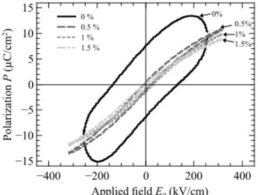
films. P ol ar iz at io n P ( µ C /c m 2) −15 −10 −5 0 5 10 15 Applied eld Ea (kV/cm) −400 −200 0 200 400 0 % 0.5 % 1 % 1.5 % 1.5% 0.5% 1% 0%
Figure 3. Hysteresis loops of the BST(80/20) films with different manganese dopant rates.
A typical cross section micrograph of the Ba0.80Sr0.20TiO3 film is shown in Fig.2. All films are well-crystallized, have a uniform, dense and void-free microstructure without cracks and are composed of spherical grains. The average grain size is about 60 nm which corresponds to a single layer thickness of the BST film as crystallization is done layer by layer due to the direct annealing process.
B. Dielectric characterization
In order to verify the influence of the Mn doping effect on the ferroelectric properties, the 50 Hz P − E hysteresis loop of the BST thin films was measured at room tempera-ture (Fig.3). The undoped film has an open loop indicating important losses. The doped films show a rather slim ferro-electric loop with a very small coercive field and remnant po-larization typical of the BST 80/20 composition. The effect of the manganese doping is clearly visible as a small amount of manganese is sufficient to considerably reduce the losses. For all the doped films, the polarization at saturation and the co-ercive field do not show a significant evolution: the values are approximately 11µC/cm2and 10 kV/cm, respectively, which is similar to what is reported elsewhere21,22. This corresponds
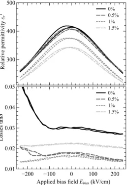
R el at iv e pe rm it ti vi ty εr ' 300 400 500 0% 0.5% 1% 1.5% L os se s ta nδ 0.01 0.02 0.03 0.04 0.05
Applied bias eld Ebias (kV/cm)
−200 −100 0 100 200
0% 0.5% 1% 1.5%
Figure 4. Relative permittivity and losses as a function of the applied bias field at 100 kHz for the different manganese dopant rates.
to a soft material, easy to polarize/depolarize, with a large dis-tribution of the coercive field which is centered on a relatively low value. This might be due to the crystallization of the BST in small spherical grains with different orientations.
The dielectric properties of the BST thin films at 100 kHz as a function of the DC bias electric field are shown in Fig.4. Addition of manganese affects the relative permittivity which decreases with increasing doping content. This is generally attributed to the increasing number of non-ferroelectric cells when incorporating the dopant into the material. Of course, this is probably not the only reason and further investigations are reported in sectionIII C. The dielectric losses are signif-icantly affected by the doping. Introduction of a small rate of manganese strongly reduces the dielectric losses until an optimum at 1% of Mn. In the case of the undoped material and for 0.5% manganese doping, the dielectric losses increase for the negative applied bias field which shows that charges accumulate at the electrodes, indicating that the doping is not sufficient in order to compensate the oxygen vacancies. Oxy-gen vacancies are polar defects which break the symmetry of the loop23,24 and doping hence improves the loop symmetry
by compensating these vacancies. In the case of BST real-ized by the sol-gel method, the annealing probably leads to a significant concentration of oxygen vacancies at the interface between the ferroelectric and the bottom electrode. Contrary to the application of a negative field which allows a movement of these oxygen vacancies toward the top electrode, no migra-tion is possible when the field is positive and no losses due to the diffusion are observed. Moreover, the diffusion of the oxygen vacancies, characterized by a complex conductivity, increases the values of the permittivity and of the losses and
T un ab il it y nr ( % ) 0 10 20 30 40 50 F ig ur e of M er it 0 10 20 30 40 50 Manganese content (%) 0 0.5 1 1.5 Tunability FoM
Figure 5. Tunability and figure of merit under 235 kV/cm at 100 kHz and as a function of the manganese content.
a dissymmetry is thus observed for both loops. The diffusion losses are then more important as the applied field is high and this can lead to breakdown.
The tunability nr and the figure of merit at 100 kHz of the BST thin films are given in Fig.5. The tunability represents the variation of the permittivity under an applied DC electric field and has been evaluated with the usual definition25:
nr=
εr(0) − εr(E) εr(0)
× 100, (3)
where εr(0) and εr(E) are the permittivity without and under the bias electric field E. For all dopant rates the tunability is around 38% under 235 kV/cm, which is similar or higher than reported elsewhere13,26. The tunability slightly decreases
with the dopant rate which might be due to the presence of an increasing number of non-ferroelectric cells containing man-ganese. The figure of merit (FoM) is defined by:
FoM= nr
tan δEc(%)
, (4)
where tan δEc(%) corresponds to the losses at the coercive
field, given in percentage. The FoM reflects the fact that a tunable microwave component cannot take full advantage of a high tunability if the loss factor is important13. In our case,
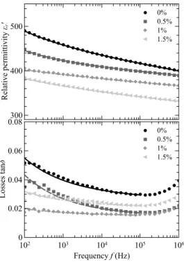
the FoM is highest for a dopant rate of 1% since the tunabil-ity almost does not vary and the losses are minimal. A man-ganese dopant rate of 1% hence offers the best compromise between tunability and losses. At 1.5% doping, the FoM de-creases showing that the losses are more important due to sup-plementary defects created by the introduction of manganese. The relative permittivity and the dielectric losses of the BST films as a function of frequency are presented in Fig.6. As it has been shown before (cf. Fig4), doping results in a decrease of the permittivity. However, it should be noted that the decay of permittivity with frequency is less pronounced in the case of 1% manganese doping. A similar evolution as a function of frequency can be observed for the dielectric losses. For 1% Mn, tan δ is quasi-constant while it increases at low fre-quencies for the others dopant rates. This shows that there are diffusion phenomena that affect both, the value of the permit-tivity and the dielectric losses, also confirming what has been
4 R el at iv e pe rm it ti vi ty εr ' 300 400 500 0% 0.5% 1% 1.5% L os se s ta nδ 0 0.02 0.04 0.06 0.08 Frequency f (Hz) 102 103 104 105 106 0% 0.5% 1% 1.5%
Figure 6. Relative permittivity and dielectric losses as a function of frequency for the different manganese dopant rates. The increase of
the losses above 105 Hz is artificial and due to a resonance of the
impedance analyzer.
stated before (cf. Fig.4). A dopant rate of 1% of manganese is adequate to compensate the oxygen vacancies and hence es-tablishes the best condition for applying the bias field. When the amount of the dopant becomes too important, the losses again increase because others defects are created.
In conclusion, the measurements show that the doping is necessary for reducing the low and high frequencies losses of the BST, however, it slightly reduces the material’s tunability. For the optimum dopant rate, the frequency dependence of the dielectric properties is less pronounced. In order to have fur-ther analysis, it is necessary to identify the different parts of the permittivity. The hyperbolic law was hence used to disso-ciate the contributions of the lattice and of the vibrations and jumps of the domain walls. The contribution of the diffusion that appears at low frequencies was also taken into account.
C. Study of the different permittivity contributions
To determine the different contributions to the permittiv-ity and the dielectric losses in the material, the complex per-mittivity as a function of the AC electric field has been an-alyzed. The dependence of the material’s relative permittiv-ity on the applied alternative field is shown in Fig.7. In the case of ferroelectrics like BST(80/20), the hyperbolic law al-lows not only obtaining the Rayleigh coefficient but also the threshold field and the permittivity due to the domain wall vibrations27–29. This is not the case of a polynomial
devel-opment which is sometimes used and where the coefficients
R el at iv e pe rm it ti vi ty εr ' 376 378 380 432 434 436
Applied electric eld Ea (V/µm)
0 0.2 0.4 0.6 0.8 1
Hyperbolic law 0% Mn 1% Mn
Figure 7. Examples of the hyperbolic law fits at 10 kHz for undoped BST and for a 1% manganese dopant rate.
of the polynomial do not have a simple relationship with the Rayleigh coefficient27,29. If we consider the amplitude of this field Ea, the permittivity can be described by:27
εr = εrl+ q
ε2
r-rev+ (αrEa)2, (5) where εrl corresponds to the lattice contribution, εr-rev to the contribution due to domain wall vibrations (also called re-versible contribution) and αrto the contribution due to domain wall pinning/unpinning (also called irreversible contribution). εr-revand αrdepend on the crystal structure but αralso reflects the presence of impurities, dopants or defects30. The different parameters also depend on the frequency28. The decompo-sition of the complex permittivity is shown in Fig.8for the different dopant rates and as a function of the frequency.
The most important contribution to the permittivity comes from the lattice εrl (Fig.8a) and shows the same evolution as the overall permittivity (Fig.6). According to Joncher31, far away from a relaxation, the permittivity varies following a power law:
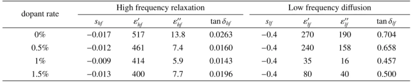
εrl= εhfωshf + εlfωslf, (6) where εhfωshf and εlfωslf represent respectively the high fre-quency relaxation and the low frefre-quency diffusion31.
Fit-ting of the experimental data (standard error of least squares method) is presented in Fig.8aand the coefficients are given in TableI.
According to the Kramer-Kronig relations (invariance of a power law by K.-K. relations), the exponents of the two contri-butions are the same for the real and the imaginary part of the permittivity, only the weighting coefficients vary. The expo-nent shf, representing the high frequency decrease of the per-mittivity, goes through a minimum for a dopant rate of 1%. This signifies that the properties of the film with 1% man-ganese are more stable in frequency than for the other dopant rates. On the contrary, slf, the exponent representing the low frequency diffusion, is identical for all dopant rates which in-dicates that the same conduction phenomenon is present. In this case, it may be diffusion of oxygen vacancies. For diffu-sion, the value of slf theoretically established by Jonscher is −0.5 and does not depend on the carrier concentration32. In
εrl ' 300 400 500 600 0% 0.5% 1% 1.5% 517×ω-0.017+270×ω-0.4 460×ω-0.012+240×ω-0.4 414×ω-0.009+35×ω-0.4 400×ω-0.013+80×ω-0.4 εrl " 0 10 20 30 40 Frequency f (Hz) 102 103 104 105 106 0% 0.5% 1% 1.5% 13.8×ω-0.017+190×ω-0.4 7.4×ω-0.012+158×ω-0.4 5.9×ω-0.009+16×ω-0.4 7.7×ω-0.013+40×ω-0.4 (a) εr-re v ' 0 1 2 3 4 0% 0.5% 1% 1.5% εr-re v " 0 0.1 0.2 0.3 0.4 Frequency f (Hz) 102 103 104 105 106 0% 0.5% 1% 1.5% (b) αr " (c m /k V ) 0 0.1 0.2 Frequency f (Hz) 102 103 104 105 106 0% 0.5% 1% 1.5% 0.174×ω-0.0526 0.099×ω-0.0455 0.061×ω-0.0435 0.044×ω-0.0417 αr ' ( cm /k V ) 0.5 1 1.5 0% 0.5% 1% 1.5% 1.08×ω-0.0526 0.73×ω-0.0455 0.56×ω-0.0435 0.42×ω-0.0417 (c)
Figure 8. Real and imaginary part of the permittivity as a function of frequency, decomposed according to the hyperbolic law, showing the bulk contribution (a), and the contributions of domain wall vibrations (b) and domain wall displacements (c). The increase of the imaginary
part above 105Hz is artificial and due to a resonance of the impedance analyzer.
Table I. Exponents, weighting coefficients and dissipation factors of the different lattice contributions to the permittivity.
dopant rate High frequency relaxation Low frequency diffusion
shf ε0hf ε 00 hf tan δhf slf ε0lf ε 00 lf tan δlf 0% −0.017 517 13.8 0.0263 −0.4 270 190 0.704 0.5% −0.012 461 7.4 0.0160 −0.4 240 158 0.658 1% −0.009 414 5.9 0.0143 −0.4 35 16 0.457 1.5% −0.013 400 7.7 0.0196 −0.4 80 40 0.500
our case, the obtained value is −0.4. The difference between the theoretical and experimental values could be due to the polycrystalline character of the BST studied (change in the direction of the crystallographic axes from a grain to another), that differs from the ideal case used by Jonscher. Contrary to slf, the prefactor εlf is a function of the carrier concentration. In order to study the evolution of the dissipation factor of the high and low frequency components of the lattice contri-bution, tan δhf = ε00hf/ε
0
hf and tan δlf = ε00lf/ε 0
lf have been cal-culated and are reported in TableI. When the dopant rate in-creases, the high frequency losses tan δhfdecrease because the introduction of the manganese compensates oxygen vacancies in the lattice. If doping becomes too important (1.5%), the losses increase due to the creation of additional defects. The coefficients representing the low frequency diffusion ε0
lf and ε00
lf are quite important for the undoped and the 0.5% doped films, especially for the losses. In the case of 1% Mn dop-ing the coefficient representing the diffusion becomes very small and hence only little diffusion is observed. It is
im-portant to note that ε00
lf is more than ten times smaller for this dopant rate than for the undoped and 0.5% doped film. This explains the observed high losses under bias field when the amount of doping is too low (Fig.4). For the dopant rate of 1.5%, the diffusion losses again slightly increase due to the addition of defects, similar to what is observed for the high frequency contribution. The dissipation factor value is very important which shows that the diffusion is a very dissipative phenomenon. Again the minimum of the losses appears for a dopant rate of 1%.
In conclusion on the influence of Mn doping on the lat-tice contribution to the material’s permittivity, one can note that the dissipation factor value tan δlf is very important which shows that diffusion is a very dissipative phenomenon. Addi-tion of manganese compensates the oxygen vacancies present in the material and hence reduces the low frequency diffusion. The dopant rate has to be sufficient in order to compensate all the vacancies but should not be too important such as to create new additional defects. The minima of the coefficients are ob-served at a dopant rate of 1% Mn which seems to be optimum
6
Table II. Exponents, weighting coefficients and dissipation factors of the domain wall pinning/unpinning contribution.
dopant rate sα α0f α 00 f mα 0% −0.0526 1.08 0.174 0.161 0.5% −0.0455 0.73 0.099 0.136 1% −0.0435 0.56 0.061 0.109 1.5% −0.0417 0.42 0.044 0.104
for reducing high frequency losses and low frequency di ffu-sion. Moreover, the frequency dependence of the material’s properties is lowest at this dopant rate.
Compared to the lattice part, the contribution of the do-main walls, vibrations (Fig.8b) and irreversible displacements (Fig.8c), to the material’s permittivity are small. As a conse-quence, the contribution due to domain wall vibrations εr-rev is quite difficult to obtain and its evolution with the dopant rate is not clearly visible in Fig.8b. The portion of the do-main wall vibrations on the overall permittivity is below 0.5%. The parameters αr, describing the irreversible displacement (Fig.8c) are approximately 0.2 to 0.8 cm/kV for the real part and 0.02 to 0.15 cm/kV for the imaginary part which is ap-proximately ten times smaller than reported for other materi-als like PZT33 or BZT34. In comparison, the contribution of
irreversible domain wall displacements to the total dielectric permittivity (αrEa/εr) is approximately 21% at 30 kV/cm for a PZT thin film33 whereas it is only 5% in the case of the
BST(80/20). The total contribution of domain walls is thus very low for BST(80/20) compared to what is found for PZT. As a consequence, the influence on the domain wall behavior from doping is not observable on the hysteresis loops shown in Fig.3and only the contribution of diffusion and of the lat-tice are visible. The concentration of domain walls seems to be low which might be due to the small grain size in the BST thin film.
The manganese doping also affects the domain wall dis-placement facility since the irreversible part decreases with increasing doping (Fig.8c). This irreversible part seems to de-crease with a power law of the frequency following the equa-tion:
αr= αfωsα, (7)
where αf represents the irreversible contribution at ω = 1 rad/s and sαindicates the frequency dependence of αr. Like-wise the case of the lattice contribution, the same exponent has been used for fitting the real and the imaginary parts in order to satisfy the K.-K. relations. The logarithm law as proposed by Taylor33has not been chosen because according to the
K.-K. relations, the imaginary part has to be constant if the real part follows a logarithm decrease, which is not the case here. Nevertheless, as the frequency dependence is very small, both laws are very close to each other.
The irreversible domain wall contribution coefficient αrhas been fitted and the real and imaginary coefficients α0
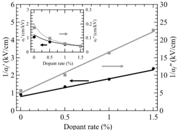
f and α 00 f show the same evolution as a function of the dopant rate (in-set of Fig. 9). The inverse of α0
f and α 00 f increases linearly αf ' ( cm /k V ) 0 1 2 3 αf " (c m /k V ) 0 0.1 0.2 0.3 Dopant rate (%) 0 0.5 1 1.5 1/ αf ' ( kV /c m ) 0 1 2 3 4 5 6 1/ αf " (k V /c m ) 0 5 10 15 20 25 30 Dopant rate (%) 0 0.5 1 1.5
Figure 9. Inverse of the coefficients α0
f and α
00
f obtained by fitting of
the irreversible part of the permittivity.
with the Mn doping (Fig.9). This is in agreement with the statistical theory of Boser30and shows that manganese acts as a pinning center and represents an obstacle to large distance domain wall motion35. As a consequence, the domain wall
mobility and hence the contribution of the domain walls is re-duced and the permittivity and the tunability of the material become smaller.
The dissipation factor mα = α00f/α0f of the domain wall pinning/unpinning has been computed and is reported in Ta-bleII. The obtained values are lower than predicted by the Rayleigh model (mα ≈ 0.5) and what has already been re-ported elsewhere36. As the wall density is small, there is only
little interaction between the walls and the losses associated to αr are low. The dissipation factor also decreases with the amount of doping showing that the phenomenon becomes less dissipative. This is due to the fact that the pinning centers are deeper and the domain structure is stabilized37, which results
in less losses. The frequency dependence of the irreversible domain wall contribution, represented by sα, also decreases with the addition of manganese as reported before35. This may be due to the fact that the introduction of a large num-ber of acceptors defects stabilize the domain walls, the relax-ation associated to domain wall pinning appears then at lower frequencies38.
Finally, all the results from the domain wall characteriza-tions indicate that the manganese doping leads to a hardening of the BST(80/20): the coefficient α0
f associated to domain wall pinning decreases when increasing the dopant rate and the pinning losses are reduced which correspond to a stabiliza-tion of the walls. Similar results are reported for PZT when an acceptor dopant is used in order to increase its hardness37. The
main difference is that BST(80/20) is initially a soft material with a low domain wall density.
IV. CONCLUSION
Ion substitution at the B-site of the perovskite lattice of Ba0.80Sr0.20TiO3 (BST 80/20) thin films by Mn2+ ions has been investigated in order to study the effect of the doping on the dielectric properties. The BST 80/20 composition is
located near to the ferroelectric-paraelectric structural phase boundary and hence has a high tunability. Introduction of a small amount of the manganese dopant prevents diffusion due to oxygen vacancies since manganese is an electron accep-tor and hence considerable reduction of the dielectric losses is observed. As the manganese substitution creates non ferro-electric cells, the permittivity and tunability of the thin film, however, slightly decrease. At higher manganese content, ad-ditional defects are created in the material and the diffusion losses rise again. Doping with 1% manganese results in the best figure of merit.
Utilization of the hyperbolic law allows us to discern the different components of the material’s complex permittivity. Thus it is shown that the contributions of domain wall motion (vibrations and displacements) are rather small compared to the lattice contribution. By dissociating the two contributions to the lattice permittivity, we show that an appropriate dopant rate considerably reduces low frequency diffusion (by a fac-tor higher than ten) while diminishing high frequency losses at the same time. The addition of manganese also reduces the domain wall mobility by the creation of additional pinning centers and hence the contribution to the complex permittiv-ity and tunabilpermittiv-ity. The doping corresponds to a hardening of the BST since the domain structure is stabilized, the domain wall pinning/unpinning is limited and the associated losses are reduced. Therefore reducing the domain wall contribution is then beneficial for decreasing the material’s dielectric losses since wall motion is a very dissipative phenomena. Doping with 1% of manganese thus is a compromise between reduc-ing the domain wall contribution (constitutreduc-ing only a small part of the permittivity) and maintaining a high tunability and low dielectric losses due to the lattice contribution which is responsible for the predominant part of the material’s overall properties.
Moreover, it has been shown that the dielectric properties of the BST thin films are rather stable over many frequency decades and no increase of the losses at low frequencies is observed at the optimum dopant rate of 1% manganese. Lim-iting the low frequency diffusion losses is essential in order to prevent breakdown when a DC field is applied. This is partic-ularly important for the use of ferroelectric materials in tun-able microwave components where a high tunability and low losses are required and stability of the dielectric properties is mandatory.
ACKNOWLEDGEMENTS
The authors would like to thank S. Ginestar for the realiza-tion of the SEM image. The financial support of the CNRS (Centre National de Recherche Scientifique) and the French Region “Pays de la Loire” is gratefully acknowledged.
REFERENCES
1S. Lahiry and A. Mansingh,Ferroelectrics 329, 39 (2005).
2B. Baumert, L.-H. Chang, A. Matsuda, T.-L. Tsai, C. J. Tracy, R. Gregory,
P. Fejes, N. Cave, W. Chen, D. Taylor, T. Otsuki, E. Fujii, S. Hayashi, and
K. Suu,Journal of Applied Physics 82, 2558 (1997).
3H. Gundel, R. Renoud, C. Borderon, S. Pavy, A. Sharaiha, V. H. Nguyen,
R. Benzerga, and C. Delaveaud, inIEEE International Symposium on the
Applications of Ferroelectrics(2012) pp. 1–4.
4K. Nadaud, R. Gillard, E. Fourn, H. Gundel, and C. Borderon, in
Lough-borough Antennas and Propagation Conference(2014) pp. 214–217.
5G. Choi, H. Tuller, and D. Goldschmidt,Physical Review B 34, 6972
(1986).
6M.-C. Chiu, Y.-C. Lee, and F.-S. Shieu,Journal of The Electrochemical
Society 152, 194 (2005).
7J. Kim, S. Kim, W. Kim, T. Ha, I.-S. Kim, J.-S. Song, R. Guo, and
A. Bhalla,Materials Letters 60, 2322 (2006).
8K.-T. Kim. and C.-I. Kim.,Thin Solid Films 472, 26 (2005).
9L. Mingli, X. Mingxia, L. Hui, L. Xiaolei, and X. Tingxian,Acta
Physico-Chimica Sinica 24, 1405 (2008).
10M. Jain, S. Majumder, R. Katiyar, F. Miranda, and F. Van Keuls,Applied
Physics Letters 82, 1911 (2003).
11W. Hofman, S. Hoffmann, and R. Waser,Thin Solid Films 305, 66 (1997).
12K.-T. Kim. and C.-I. Kim.,Microelectronic Engineering 66, 835 (2003).
13C. Borderon, D. Averty, R. Seveno, and H. W. Gundel,Integrated
Ferro-electrics 97, 12 (2008).
14X. Du and I.-W. Chen,Journal of Applied Physics 83, 7789 (1998).
15B. Mitchell,An Introduction to Materials Engineering and Science for
Chemical and Materials Engineers(Wiley, 2004).
16N. Giridharan, S. Madeswaran, and R. Jayavel,Journal of Crystal Growth
237-239, Part 1, 468 (2002).
17H.-Y. Tian, W.-G. Luo, X.-H. Pu, X.-Y. He, P.-S. Qiu, and A.-L. Ding,
Materials Chemistry and Physics 69, 166 (2001).
18R. Schwartz, T. Schneller, and R. Waser,Comptes Rendus Chimie 7, 433
(2004).
19S. Hoffmann and R. Waser,Journal of the European Ceramic Society 19,
1339 (1999).
20U. Hasenkox, S. Hoffmann, and R. Waser,Journal of Sol-Gel Science and
Technology 12, 67 (1998).
21J.-G. Cheng, X.-J. Meng, B. Li, J. Tang, S.-L. Guo, J.-H. Chu, M. Wang,
H. Wang, and Z. Wang,Applied Physics Letters 75, 2132 (1999).
22T.-J. Zhang, H. Ni, and W. Wang,Journal of Materials Synthesis and
Pro-cessing 10, 17 (2002).
23G. Le Rhun, R. Bouregba, and G. Poullain,Journal of Applied Physics 96,
5712 (2004).
24W. Wu, K. H. Wong, and C. L. Choy,Applied Physics Letters 85, 5013
(2004).
25D. Dimos, M. Raymond, R. Schwartz, H. Al-Shareef, and C. Mueller,
Journal of Electroceramics 1, 145 (1997).
26C. Borderon, D. Averty, R. Seveno, and H. W. Gundel,Ferroelectrics 362,
1 (2008).
27C. Borderon, R. Renoud, M. Ragheb, and H. W. Gundel,Applied Physics
Letters 98, 112903 (2011).
28R. Renoud, C. Borderon, and H. Gundel,Ultrasonics, Ferroelectrics, and
Frequency Control, IEEE Transactions on 58, 1975 (2011).
29C. Borderon, R. Renoud, and H. Gundel, inIEEE International Symposium
on the Applications of Ferroelectrics(2010) pp. 1–4.
30O. Boser,Journal of Applied Physics 62, 1344 (1987).
31A. K. Jonscher,Journal of Physics D: Applied Physics 32, R57 (1999).
32A. Jonscher, Dielectric relaxation in solids (Chelsea Dielectrics Press Ltd,
1983).
33D. V. Taylor and D. Damjanovic, Journal of Applied Physics 82, 1973
(1997).
34J. Miao, J. Yuan, H. Wu, S. B. Yang, B. Xu, L. X. Cao, and B. R. Zhao,
Applied Physics Letters 90, 022903 (2007).
35W. Zhu, I. Fujii, W. Ren, and S. Trolier-McKinstry,Journal of Applied
Physics 109, 064105 (2011).
36J. E. García, R. Pérez, and A. Albareda,Journal of Physics: Condensed
Matter 17, 7143 (2005).
37D. Damjanovic,Reports on Progress in Physics 61, 1267 (1998).
38C. Borderon, R. Renoud, M. Ragheb, and H. W. Gundel,Applied Physics
![[Progress of the two ITAES approaches]](data:image/gif;base64,R0lGODlhAQABAIAAAP///wAAACH5BAEAAAAALAAAAAABAAEAAAICRAEAOw==)