HAL Id: hal-01207699
https://hal.archives-ouvertes.fr/hal-01207699
Submitted on 7 Oct 2015
HAL is a multi-disciplinary open access
archive for the deposit and dissemination of
sci-entific research documents, whether they are
pub-lished or not. The documents may come from
teaching and research institutions in France or
abroad, or from public or private research centers.
L’archive ouverte pluridisciplinaire HAL, est
destinée au dépôt et à la diffusion de documents
scientifiques de niveau recherche, publiés ou non,
émanant des établissements d’enseignement et de
recherche français ou étrangers, des laboratoires
publics ou privés.
polymer (AFRP) rebar/concrete interfaces
Arnaud Rolland, Sylvain Chataigner, Karim Benzarti, Marc Quiertant, Pierre
Argoul, Jm Paul
To cite this version:
Arnaud Rolland, Sylvain Chataigner, Karim Benzarti, Marc Quiertant, Pierre Argoul, et al..
Mechan-ical behaviour of aramid fiber reinforced polymer (AFRP) rebar/concrete interfaces. TRA 2014, Apr
2014, PARIS, France. 10p. �hal-01207699�
Transport Research Arena 2014, Paris
Mechanical behaviour of aramid fiber reinforced polymer (AFRP)
rebar/concrete interfaces
A. Rolland
a,*, S. Chataigner
b, K. Benzarti
a, M. Quiertant
a, P. Argoul
a,c, J-M. Paul
ba
Université Paris-Est, IFSTTAR, F-77447 Marne-la-Vallée, France
bLUNAM Université, IFSTTAR, F-44341 Bouguenais, France
cUniversité Paris-Est, Laboratoire Navier, F-77455 Champs-sur-Marne, France
Abstract
Aramid Fiber Reinforced Polymer (AFRP) rebars are being used as internal reinforcements of concrete structures for more than ten years. Their main advantages over common reinforcing steel rebars rely on their lightness, durability performances, mechanical properties, and electromagnetic neutrality. For this application, interfacial properties between the rebars and surrounding concrete play a major role on the mechanical performances of the reinforced concrete structure. In this context, this research aims at investigating the bond behaviour of commercially available AFRP rebars embedded in concrete. The first part of the paper is devoted to the assessment of mechanical and physical properties of the selected rebars. A second part is then dedicated to the study of interfacial properties between the rebars and concrete: the interfacial bond strength is first assessed using a specifically designed pull-out test, and a modelling of the interface behaviour is then developed, based on an analytic bond-slip law. The method used to identify key theoretical parameters of the model is also discussed.
Keywords: Reinforced concrete; AFRP rebars; Pull-out tests; Modelling; Parameter identification.
Résumé
Les armatures en Polymère Renforcé de Fibres d’Aramide (PRFA) sont utilisées pour le renforcement des structures en béton depuis plus de dix ans. Leurs principaux avantages au regard des armatures traditionnelles en acier réside dans leur légèreté, leur durabilité, leurs propriétés mécaniques, et leur neutralité électromagnétique. Un point clé gouvernant l’efficacité de tels renforcements réside dans leur capacité à adhérer correctement au béton. La présente étude s’intéresse donc à la caractérisation de l’adhérence entre le béton et des armatures en PRFA disponibles sur le marché. La première partie de l’article est consacrée à la présentation des armatures étudiées et à la caractérisation de leurs principales propriétés physiques et mécaniques. La seconde partie de l’étude s’intéresse à la détermination du comportement mécanique à l’interface entre les armatures et le milieu béton. Le comportement de l’interface est tout d’abord évalué à l’aide d’un essai d’arrachement spécialement conçu, puis est analysé au travers d’une modélisation originale. Pour mettre en œuvre cette dernière, une méthode d’identification des paramètres du modèle est proposée.
Mots-clé: Béton armé; Armatures PRFA ; Essais d’arrachement ; Modélisation ; Identification de paramètres.
*
1. Introduction
Corrosion of steel reinforcing bars (rebars) is the main cause of deterioration of concrete structures. Consequently, some researchers investigated the use of alternative reinforcing materials such as advanced fiber reinforced polymers. This technology is being used for almost ten years in some countries such as Canada or the USA (Benmokrane et al., 2012), and specific design guidelines and test procedures have been developed to characterize this type of material and promote its introduction in new structures (JSCE, 1995) (ACI, 2004) (ISIS, 2006) (FIB, 2007) (CNR-DT, 2007) (ACI, 2008). A wider use of such a technology would have a beneficial effect on durability, and may thus lead to decrease the total cost of a structure as shown in (Eamon et al., 2012). The present work is concerned with braided Aramid Fiber Reinforced Polymer (AFRP) rebars that are produced in Japan by Fibex® Company (Fig. 1). Both plain and sand coated AFRP rebars are studied. This research is the continuation of an ongoing investigation program focusing on this material (Rolland et al., 2013) (Chataigner et
al., 2013). The first part of the paper presents the experimental characterizations that were conducted on the
composite rebars, including microscopic observations, tensile tests, determination of the glass transition temperature of the polymer matrix, and measurement of the thermal expansion coefficient. Considering that the bond properties between the rebars and surrounding concrete is a key point in relation to the performance of AFRP reinforced structures, the second part of the paper focuses on pull-out tests that were performed to characterize the bond behaviour. Finally, the last part is devoted to the modelling such the interfacial behaviour using a bond-slip analytical model.
Fig. 1. Pictures of the studied rebar: (a) straight rebars; (b) bent-shaped rebar.
2. Material properties at ambient temperature
Braided AFRP rebars are produced by a specific manufacturing process: .braided aramid ropes are first impregnated in an epoxy bath before being stretched and cured in a continuous production line. Produced rebars are non-corrosive, non-magnetic and non-conductive.
2.1. Microscopic observations
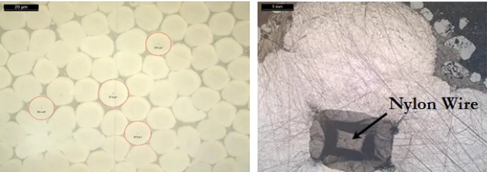
Some microscopic observations were led in order to get a thorough understanding of the structure of the rebar and to investigate the presence of default such as voids for instance. Some pictures showing the fiber arrangement are presented in Fig. 2. The rebar is composed of four braided bundles of aramid fibers having diameters ranging from 15 to 18 micrometers, and twisted around a central nylon wire..No inclusions and no voids could be detected, suggesting a good quality of the manufactured products. For the reinforcement of concrete structures, Fibex® Company produces also sand coated AFRP rebars, which are expected to show better bond performances.
Fig. 2. Microscopic observations of the cross-section of the studied rebar.
A. Rolland, S. Chataigner, K. Benzarti, M. Quiertant, P. Argoul, J-M. Paul Transport Research Arena 2014, Paris
2.2. Tensile tests
For purposes of tensile testing, specific anchorage systems were developed in accordance with (ACI, 2004). 20 cm long steel tubes were sealed with cement based grouting mortar at the gripping ends of the rebars (see Fig. 3). This type of anchorage made it possible to obtain systematically tensile failures in the middle part of the tested rebars, as depicted in Fig. 3. Tests were performed onAFRP rebars of diameter 11mm, with a free length of 600 mm between the 2 anchorages. A mean tensile capacity of 106 kN was found, based on a series of three tests,, corresponding to a mean tensile strength of 1120 MPa. The rebars exhibited an elastic and brittle behaviour, with a mean elastic modulus of 72 GPa.
Fig. 3. Picture showing the fracture mode after a tensile test.
2.3. Glass transition temperature
Analyses were carried out by Differential Scanning Calorimetry (DSC), in order to assass the glass transition temperature Tg of the epoxy matrix according to (ASTM, 2008). Moreover, for security purpose it is important to
check that Tg is much higher than the expected ultimate service temperature of the rebar embedded in the
reinforced structure. Three detrminations were done on small samples of plain rebars weighing 4-5 mg, placed in aluminium pans and analyzed using a TA Instruments® DSC Q100 calorimeter. Specimens were heated using a modulated ramp of temperature from 0 to 200 °C, at a heating rate of 1.5 °C/min, with a modulation period of 60 s and an amplitude of 0.239°C. A Tg value of 71,6 °C ± 2,1 °C was obtained by this method, and an example of
thermogram is illustrated in Fig. 4. It is important to note that the Tg may vary depending on the curing cycle
adopted for the rebar
Fig. 4. Example of thermogram provided by DSC experiments.
2.4. Thermal expansion
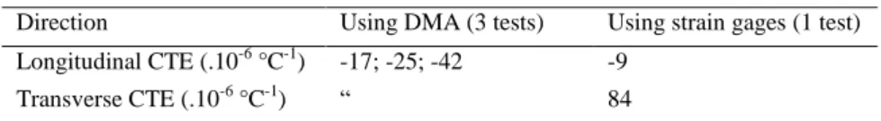
A major advantage of steel in the framework of civil engineering application is certainly the fact that it has a thermal expansion close to that of concrete. This is not always the case for alternative materials, and especially for composite rebars as raised in (Ceroni et al., 2006). Measurements were carried-out according to two different methods, in order to evaluate the the Coefficients of Thermal Expansion (CTE) in the longitudinal and transversal directions,(with respect to the fiber axis), as composite rebars are known to be orthotropic. Dynamic Mechanical Analyses (DMA) were first performed to assess the longitudinal CTE between 20 and 60°C. The second method involves the use of strain gages and of a climatic chamber. One gauge was bonded in the
longitudinal direction and another one in the transverse direction. An additional strain gage was used to compensate for the expansion of the measurement system alone. A picture of the experimental setup is given in Fig. 5.
Results of measurements are summarized in Table 1. A large dispersion is observed for the longitudinal CTE values derived from DMA experiments, Moreover, the 2 methods provide very different values for this longitudinal CTE. Nevertheless, results from the strain gage measurements are in agreement with data found in the literature for AFRP composite bars (Erki and Rizkalla, 1993; Ceroni et al., 2006). Additional investigations are currently in progress to check the previous results, especially for the transversal CTE is concerned.
Fig. 5. Picture of an AFRP rod sample, equipped with strain gages for CTE measurements Table 1. Experimental evaluation of the coefficients of thermal expansion.
Direction Using DMA (3 tests) Using strain gages (1 test) Longitudinal CTE (.10-6 °C-1) -17; -25; -42 -9
Transverse CTE (.10-6 °C-1) “ 84
3. Bond tests
In order to investigate the bond behaviour between the rebar and surrounding concrete, pull-out tests were carried out. Although, this test procedure may not be the most representative, it is the most simple and quick to realize.
3.1. Geometry and preparation of the pull-out specimens
The geometry of the test specimens is described in Fig. 6. Two batches of concrete, named B1 and B2, were used for the preparation of the pull-out samples. The compressive strength of concrete was assessed on cylindrical specimens of diameter 160 mm, with respective values of Rc1 = 36.1 MPa and Rc2 = 34.1 MPa for the 2 batches.
Different series of pull-out specimens were prepared, using steel bars (for control samples), plain and sand coated AFRP rebars of various diameters. The adopted anchorage length was six times the rebar diameter d for all test series (see Fig. 6). The objective was to investigate the effects of the diameter and the sand-coating on the bond properties between AFRP rods and concrete, and to make a comparison with traditional steel rebars
A. Rolland, S. Chataigner, K. Benzarti, M. Quiertant, P. Argoul, J-M. Paul Transport Research Arena 2014, Paris
3.2. Test procedure
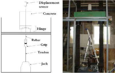
Tests were carried-out on a 350kN tensile testing machine. A tendon and specific grips allowed the application of the force to the rebar. The concrete block is supported by a steel beam drilled in the middle so that the rebar can pass through it. The displacement at the free end of the sample is measured during the test (Fig. 7) and the displacement rate is set constant at 1.3 mm/min, as recommended in (ACI, 2004).
Fig. 7. Scheme of the pull-out test and picture of the testing machine.
3.3. Results
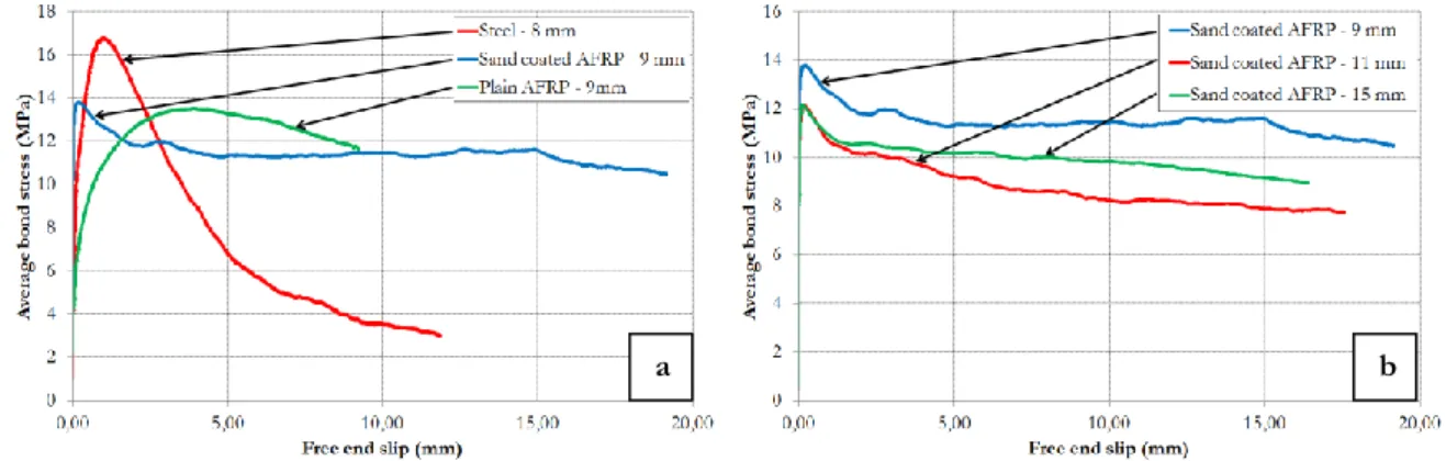
The measured ultimate capacities are listed in Table 2. Average shear stress versus displacement curves are illustrated in Fig. 9 for tests performed on specimens with steel, plain and sand coated AFRP bars of various diameters. Three samples were tested for each diameter of AFRP rebars and two for steel rebars. In Table 2, the bond strength refers to the maximum value of the average bond stress, where the failure occurs. The bond stress is calculated as the ratio between the applied force and the embedded area of the bar.
It is interesting to note that only a small difference is found between specimens with steel and AFRP rebars, as far as the two smaller rebar diameters are considered. However, a large difference is noticed for the larger diameter. Besides, the sand-coating does not notably modify the ultimate pull-out capacity. In the case of composite rebar, it can be observed that the bond strength decreases as the rebar diameter increases. Some pictures of the failure modes are given in Fig. 8. In the case of the steel rebars, failure occurs within concrete, thus creating a sliding plane around the bar. In the case of AFRP rebars, it seems to occur in the rebar close to the interface for both sand-coated and plain samples. Similar results were found in previous results from the literature, suggesting that the pull out test is suitable and reproducible for bond characterization (Okamoto et al., 1988).
Table 2. Results of the pull-out tests. Type of
rebar
Diameter (mm)
Concrete batch Ultimate capacity (kN)
Standard deviation (kN)
Ultimate average shear stress (MPa) Steel 8 B1 18.50 1.43 15.33 12 B2 38.35 4.35 14.13 16 B2 93.10 4.77 19.29 Aramid 9 B1 20.31 0.39 13.30 11 B1 38.95 1.58 17.08 15 B2 49.53 0.47 11.68 Sanded aramid 9 B1 20.90 0.21 13.69 11 B1 24.55 3.14 10.76 15 B2 53.71 2.35 12.66
Fig. 8. Typical failure modes observed after pull-out tests.
Fig. 9. Examples of average bond stress versus displacement curves for : (a) Steel rebar, plain and sand-coated AFRP rebar, and (b) 9 mm, 11 mm, and 15 mm sand-coated AFRP rebar.
4. Modeling
This part deals with the analytical modelling of the interface behaviour between the rebar and the concrete during a pull-out test. This behaviour is governed by a bond-slip law τ(s), with τ the interfacial shear stress (in MPa) and s the relative slip (in mm).
This analytical bond-slip may be further implemented in finite element codes, using cohesive zone models, to simulate the behavior of reinforced concrete structures.
4.1. Analytical law considered
Some analytical models have already been proposed in literature, and the most cited are the BEP (Eligehausen et
al., 1982) and CMR (Cosenza et al., 1997) models. The typical responses associated to these models are
represented in Fig. 10. The response for a monotonic pull-out loading consists in a first nonlinear ascending branch until the ultimate shear stress τ1, followed by a linear decreasing branch (an additional floor is proposed
in the BEP model), until a residual constant shear stress τ3. The expression of the ascending branch proposed by
BEP is
1 1s
s
, whereas the CMR expression is
sr se
1
1 .Fig. 10. Typical responses of (a) the BEP model and (b) the CMR model.
A. Rolland, S. Chataigner, K. Benzarti, M. Quiertant, P. Argoul, J-M. Paul Transport Research Arena 2014, Paris
Both theses expressions lead to an infinite slope at the origin point s = 0. For this reason, the implementation of these analytical laws into a finite element model is not possible (infinite initial stiffness). Thus, we propose the following expression of the analytical bond-slip law τmodel(s):
R R R M M R M R M M M M M M els
s
s
s
s
s
s
s
s
s
s
s
s
s
s
s
s
s
]
;
[
)
(
]
;
0
[
)
(
)
(
)
(
m od (1)The typical response associated to the proposed model is represented in Fig. 11. The response for a monotonic pull-out loading consists first in a nonlinear (homographic shape) ascending branch until the ultimate shear stress
τM, followed by a linear decreasing branch, until a residual constant shear stress τR. The slope at s = 0 has a finite
value T M M M
s
s
K
s s
.Fig. 11. Bond-slip law
model( )
s
of the proposed model.4.2. Parameter identification method
The proposed model (Eq. 1) is governed by five parameters τM, sM, sα, τR, and sR that can be collected in the
vector
:
T
Ms
Ms
Rs
R
.The objective of this part is to identify all these parameters from experimental pull-out data (si , i) for 1≤i≤n, n
being the number of measurement points. The identification procedure consists in finding the optimal values of
by means of the least mean square minimization of the discrepancy
between the measured bond-slip law and the “exact” one given by Eq. (1), respectively. This error, called the constitutive law error, is defined by:2 model 1
( )
(
( , )) .
n i i is
(2)The identification procedure is divided into three successive steps:
(1) The value of the two parameters M and sM are estimated directly on the experimental curve: M is
chosen to be the maximum recorded experimental value, and sM its corresponding slip value. The set of
experimental data (si , i) can then be divided into two parts corresponding to before and after s1. We
note n1 and n2 the number of experimental points before and after the maximum point, respectively,
(2) The value of s is estimated from the n1 first data points by the least mean squares minimization of the error function: 1 2 1 model 1
(
)
(
( ,
))
n i i is
s s
, for 0≤ si ≤ sM.(3) The values of R and sR are finally estimated from the n2 last data points by the least mean squares
minimization of the error function:
2 2 2 model 1
(
,
)
(
( ,
,
))
n R R i i R R is
s
s
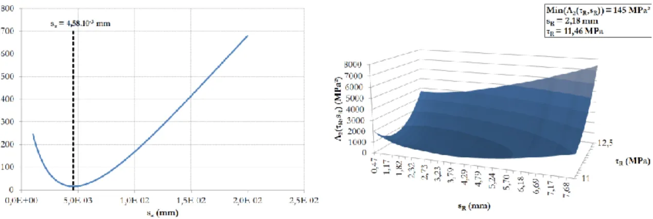
, for sM ≤ si ≤ sR. 4.3. ResultsThe method has been computed in the Scilab® environment, for experimental results of two 9 mm diameter sanded AFRP rebars and two 8 mm diameter steel rebars, due to their good representativeness. Fig. 12 represents the plots of the two error functions
1(
s
)
and
2(
R,
s
R)
for one of the AFRP rebars.The minimum of
1(
s
)
is reached for sα = 4.58.10-3 mm, and the minimum value of the surface
2(
R,
s
R)
is reached for sR = 2.18 mm and τR = 11.46 mm.
Fig. 12. Error functions related to the parameter identification: illustration for the 9 mm diameter AFRP rebar.
The results of the parameter identification procedure are summarized in Table 3. The curves of experimental bond-slip behaviour laws are drawn in Fig. 13 for the steel rebars and in Fig.14 for the sanded AFRP ones and they are compared to simulations obtained with the identified parameters. A good agreement can be noticed between the analytical and experimental curves.
In a further study, the next step will consist in identifying the parameters on a large set of experimental results. This identified bond-slip law will then be implemented in a finite element code, using cohesive zone models elements, to simulate the behavior of reinforced concrete structures, taking into account the interfacial phenomenon.
Table 3. Identified parameters.of the model
Rebar Diameter (mm) s1 (mm) τM (MPa) sα (mm) s2 (mm) τR (MPa)
Sanded aramid rebar 1 9 0.18 13.83 4.58 .10-3 2.18 11.46 Sanded aramid rebar 2 " 0.42 13.55 5.50 .10-3 1.86 12.12 Steel rebar 1 8 0.99 16.80 110.7 .10-3 6.06 4.40 Steel rebar 2 " 1.08 16.51 65.8 .10-3 5.25 5.18
A. Rolland, S. Chataigner, K. Benzarti, M. Quiertant, P. Argoul, J-M. Paul Transport Research Arena 2014, Paris
Fig. 13. Experimental and identified bond-slip behaviour laws for pull-out specimens with 8 mm steel rebars
Fig. 14. Experimental and identified bond-slip behaviour laws for pull-out specimens with 9 mm sand-coated aramid rebars.
5. Conclusions
The proposed investigations aimed at studying AFRP composite rebars used as an internal reinforcement in concrete structures, with an emphasis on the bond behavior between these bars and concrete. Tests were first conducted on the rebars alone in order to characterize their microstructure and their mechanical properties, and to check the quality of the manufacturing process as well. It made it possible to assess the maximum service temperature of such rebars in concrete. Preliminary investigations were also made regarding the determination of the coefficient of thermal expansion, but further work is needed since large dispersions were observed on experimental results.
Pull-out tests were conducted to check the adequacy of the tested method. Results were found consistent with those of previous studies from the literature, suggesting an adequate preparation of the test specimens and a proper implementation of the test characterizations. Then, a modeling approach of the pull-out test has been presented. The experimental bond-slip behavior was satisfactorily simulated by an analytical bond-slip law model, whose parameters where identified using the least squares method. Besides, this identified bond-slip law could be implemented in a finite element code, taking into account the interfacial phenomenon between rebars and concrete. Such a code will be helpful to improve the design of structures reinforced by composite rebars.
Acknowledgements
The authors wish to express a strong acknowledgement to Fibex Company for providing the AFRP composite rebar, and to the Laboratory of Autun (CETE de Lyon) that participated actively in the experimental investigations.
References
ACI. (2004). Guide test methods for Fiber-Reinforced Polymers (FRPs) for reinforcing or strengthening concrete structures. ACI 440.3R-04.
ACI. (2008). Specification for construction with Fiber-Reinforced Polymer reinforcing bar. ACI 440.5-08. AFGC (Association Française du Génie Civil). (2011). Réparation et renforcement des structures en béton au moyen des matériaux composites – Recommandations provisoires. Documents scientifiques et techniques. ASTM D 3418. (2008). Standard Test Method for Transition Temperatures and Enthalpies of Fusion and Crystallization of Polymers by Differential Scanning Calorimetry. ASTM.
Benmokrane, B., Ahmed, E., Dulude, C., & Boucher E. (2012). Design, construction and monitoring of the first worldwide two-way flat slab parking garage reinforced with GFRP bars. Proceedings of the International
conference on Composites In Civil Engineering CICE, Rome.
Ceroni, F., Cosenza, E., Gaetano, E., & Pecce, M. (1988). Durability issues of FRP rebars in reinforced concrete members. Cement and concrete composites, Vol. 28 (10), pp. 857-868.
Chataigner, S., Rolland, A., Benzarti, K., Dieng, L., Bouidarene, O., Paul, J. M., Quiertant, M., Argoul, P., Collet, P. (2013). Caractérisation d’armatures en PRF d’aramide utilisées dans les structures en béton armé.
18èmes Journées Nationales sur les Composites (JNC 18), Nantes, France, 10 p.
CNR-DT. (2007). Guide for the design and construction of concrete structures reinforced with fibre-reinforced polymer bars. National Research Council, Rome.
Cosenza, E., Manfredi, G., Realfonzo, R. (1997). Behaviour and modeling of bond of FRP rebars to concrete.
Journal of Composites for Construction, May 1997, pp. 40-51.
Eamon, C.D., Jensen, E.A., Grace, N.F., & Shi, X. (2012). Life cycle cost analysis of alternative reinforcement materials for bridge superstructures considering cost and maintenance uncertainties. Journal of composites for
construction, and concrete composites, Vol. 24 (4), pp. 373-380.
Eligehausen, R., Bertero, V., Popov, E. (1982). Analytical model for deformed bar bond under generalized excitations. Report No. UCB/ERC 82/23, University of California, Berkeley, USA.
Erki, M. A., Rizkalla, S. H., (1993) FRP Reinforcement for Concrete Structures. Concrete International. Vol. 15. Issue: 6. pp. 48-53.
Fib. (2007). FRP reinforcement in RC Structures, bulletin 40. Technical report.
ISIS Canada. (2006). Exigences pour l’homologation de barres d’armature en polymères renforcés de fibres pour les structures en béton. Canada.
JSCE. (1995). Quality specifications for continuous fiber reinforcing materials. JSCE-E 131-1995.
Okamoto, T., Endo, K., Matsubara, S., & Tanigaki, M. (1988). Study on braided aramid fiber rods – Part 3. Bond characteristics I – Results of pull-out tests. Summaries of technical papers of annual meeting, architectural institute of Japan.
Rolland, A., Chataigner, S., Benzarti, K., Dieng, L., Bouidarene, O., Paul, J. M., Quiertant, M., Collet, P. (2013). Low temperature bond behavior of concrete with braided aramid fiber bars. Proceedings of the 11th
International Symposium On Fiber Reinforced Polymers For Reinforced Concrete Structures (FRPRCS 11),