ISSN 0973-631X Volume 12, Number 1 (2018), pp. 1-11 © Research India Publications
http://www.ripublication.com
Control of Solvent Vapor Assisted Imprinting
Lithography Process by Real Time Monitoring of
Grating Diffraction Efficiency
Georges Horugavye, Bernard Sabushimike, Serge Habraken
Holography and Optical Laboratory (HOLOLAB), Spatial Technologies and Astrophysics Research (STAR) Institute, University of Liege
Allée du six Août 19, 4000 Liège, Belgium.
Abstract
Diffraction grating replication realized by solvent vapor assisted imprinting lithography (SVAIL) process is here reported. Diffraction efficiency was monitored in real time. The monitoring indicated the variation of diffraction efficiency during the evolution of SVAIL process. According to initial value of monitored diffraction efficiency and to theoretical simulations of diffraction efficiency for various steps of SVAIL process, the value of diffraction efficiency for optimal replication was deduced; and the process could be stopped at that value.
Keys words: replication, solvent, vapor, diffraction, grating.
1. INTRODUCTION
The realization of small structures with high fidelity is one of the replication challenges. Han LuLu et al. [1] enumerated many techniques which have been developed: replica molding [2], microtransfer molding [3], microcontact printing [4], micromolding in capillaries [5] and solvent-assisted micromolding [6].
The common key element of such techniques is an elastomer mold, usually made of polydimethylsiloxane (PDMS) [7]. And there must be a conformal contact between the PDMS mold, polymer layer and the substrate.
Factors such as molds, solvents, pressure, temperature, time and size of the pattern structures can influence the final molded patterns [1]. These factors can separately or
concurrently act on the quality of the transferred patterns during the solvent-assisted molding process for example. In that technique, due to the permeability of the PDMS mold, the solvent is capable to evaporate uniformly and the air bubbles between the interfaces can expel from the mold [8], [1].
The solvent molecules diffuse into the polymer thin film as a result of the solvent concentration gradient between the two surfaces, top and bottom [9]. The thickness of a PDMS mold plays an important role in SVAIL process. The PDMS membrane acts as a medium that transports the solvent molecules. Rabibrata Mukherjee et al. [10] combined solvent vapor-assisted swelling and patterning of polymers with the idea of using a flexible and water-soluble stamp, to develop an extremely simple, rapid, pressureless, room temperature patterning technique for high fidelity patterning of films coated on nonplanar surfaces. But to control all those parameters at the same time remained a challenge. In this work, we proposed to replicate a small structure, a diffraction grating, by solvent vapor assisted imprinting lithography (SVAIL). We used PDMS mold and we evaluated in real time the diffraction efficiency in the negative first diffraction order, during the replication process. According to theoretical simulations of different steps for SVAIL process, theoretical diffraction efficiency at optimal replication was deduced, and the reference value was predicted to stop the process. More details are mentioned in the following sections.
2. EXPERIMENT DESCRIPTION
This section describes the replication of a diffraction grating with high fidelity. A commercial diffraction grating from Thorlabs [11] with known parameters was chosen for commodity: transmission grating, spatial frequency = 600lp/mm, groove angle = 28,7°. Firstly, PDMS mold (Sylgard 184 and curing agent respectively 10:1) of the original diffraction grating had been prepared classically [7]. The thickness of the PDMS mold was here ±500µm for more flexibility. Secondly, glass substrate coated with photoresist s1805 was also prepared by spincoating. The prepared thickness film was ±700nm, in agreement with grating groove height h = 659 nm deduced from given grating parameters. Ethanol was used as solvent. That solvent was conditioned in a glass box. The latter contained at the same time a smaller one. All the two glass boxes were transparent to LASER source @ 532nm. Glass substrate coated with photoresist s1805 and the PDMS mold in perfect contact were placed inside the small box. The external box was hermetically sealed, so the solvent gas could not escape, but entered inside the small box. In such conditions, the gas reached the top face of the PDMS mold in perfect contact with photoresist, and the replication process started. Finally, SVAIL process was controlled through diffraction efficiency measured in real time (fig.1).
Figure 1. Set-up of SVAIL process and diffraction efficiency measurement in real time.
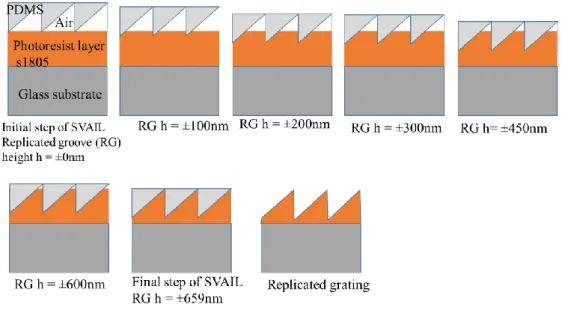
Diffraction efficiency measurement in real time was realized according to LASER source @ 532nm used as incident beam on the set (PDMS mold + photoresist s1805) in replication process. A particular attention was also taken into account in the choice of LASER source, reference to spectral band of photoresist sensibility. The incident beam was diffracted by the PDMS mold and the grating under replication process. Diffraction efficiency was measured continuously in the order-1 according to optical photometer, and data were stored directly in a computer. Reference beam from beam splitter was also measured to take into account possible LASER fluctuations. At the starting point of the SVAIL process, glass substrate coated with photoresist s1805 and PDMS mold were in perfect contact; and the grooves of the PDMS mold were full of air (fig.2, initial step of SVAIL, replicated groove height (RG h), RG h = ±0nm).
Figure 2. Illustration of SVAIL replication process for different replicated grooves height.
The diffraction efficiency results from the combination of PDMS mold and photoresist microstructures (replicated grooves). At the middle of the replication process, replicated grating had groove profile with trapezoidal shape. At the optimal point of the replication process, the grooves of the PDMS mold are full of photoresist s1805 (fig.2, groove height h = 659nm). After gratings demolding (for various durations), theoretical simulations were compared to experimental measurement results. Theoretical simulations of those three main steps (initial, middle & final) were first performed (fig.3). The refractive index used in theoretical simulations for various materials @ 532nm are here indicated: PDMS mold (n = 1.41), resin of the original grating (n = 1.68) and photoresist s1805 coated on glass substrate (n = 1.58).
3. RESULTS AND ANALYSIS
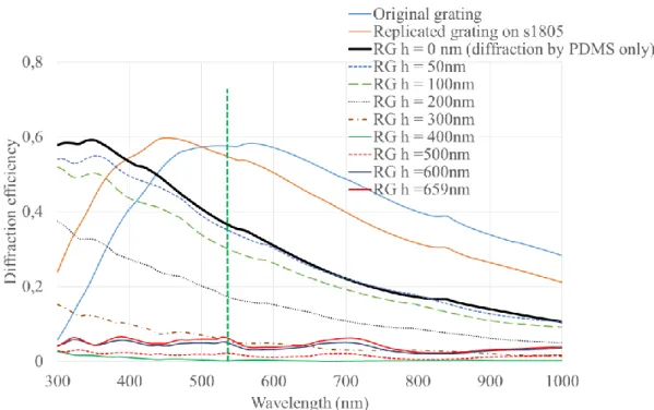
In a first step, this section presents theoretical simulations of original grating and the main steps of SVAIL process (fig.3). Based on the manufacturer datasheet, we retrieve the remaining grating parameters. Those parameters are injected as an input to the diffraction grating analysis software (PC Grate software). The curve “original grating” is simulated according to manufacturer datasheet. The similar parameters were used to simulate the diffraction efficiency of PDMS mold; and also of the replicated grating on photoresist s1805. The observed shift of their respective curves is due to refractive index which is different for those various materials.
Figure 3. Theoretical simulations of diffraction efficiency, order -1: original grating and various steps of SVAIL process as indicated on fig.2.
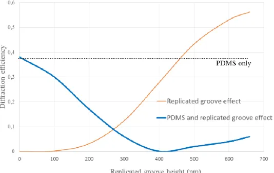
At the starting point of SVAIL process, the replicated groove height is near zero (RG h = ±0nm), and the global diffraction efficiency would be ideally equal to that of PDMS mold only. During SVAIL process, diffraction efficiency resulting of replicated groove varied, and the global diffraction efficiency followed. And from theoretical simulations (fig.3), we deduced the diffraction efficiency as a function of groove height of replicated grating (fig.4) for a single wavelength (532nm) used in diffraction efficiency monitored in real time. The curve “replicated groove effect” (fig.4) is deduced from diffraction efficiency simulations of the replicated grating (only) for various groove height (RG h = 50nm, 100nm, 200nm, 300nm, 400nm, 500nm, 600nm, 659nm) of the photoresist (trapezoidal shape).
Figure 4. Theoretical simulation of diffraction efficiency @ 532nm, due to PDMS only (horizontal line), replicated groove effect (orange curve) and combination of
PDMS and replicated groove effect during SVAIL process (blue curve).
In the second step, measurement realized in real time during SVAIL process are presented.
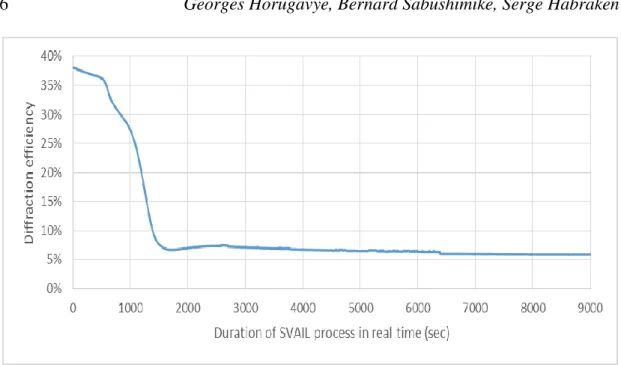
For experimental diffraction efficiency measurement in real time, LASER source fluctuations were first investigated. We observed that the LASER was stable, with the variation estimated at 0,5%. So the evolution of the diffraction efficiency was mainly related to SVAIL process. Various durations of SVAIL were also tested (30min, 1h, 2h30, 5h, 18h, 39h, 114h). All the obtained samples results were similar for the common SVAIL process duration. Hereunder (fig.5) is mentioned one of the results related to diffraction efficiency monitored in real time.
Figure 5. Experimental measurement of diffraction efficiency in real time as a function of duration of SVAIL process.
A zoom is realized (fig.5bis) for more details particularly at the first moment of the process.
Figure 5 bis. Zoom of the first moment of experimental monitoring of diffraction efficiency in real time as a function of duration of SVAIL process.
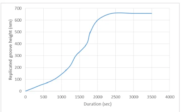
simulation for various steps of replication (table1) allowed us to deduce the groove height evolution of replicated grating during SVAIL process as a function of duration (fig.6).
Table 1: Theoretical diffraction efficiency vs experimental diffraction efficiency during SVAIL process
Replicated groove height (nm)
Theoretical diffraction efficiency (fig.4)
Experimental monitoring diffraction efficiency (fig.5)
Duratio n (sec) 0 0,37 0,38 0 50 0,36 0,36 400 100 0,31 0,3 800 200 0,18 0,19 1200 300 0,06 0,09 1400 400 0,01 0,06 1700 500 0,03 0,07 1800 600 0,06 0,07 2000 659 0,06 0,07 2400
Hereunder is the deduced graphical representation of the groove height evolution.
Figure 6. Groove height evolution of replicated grating as a function of SVAIL process duration.
The diffraction efficiency obtained theoretically according to the combination of the two effects, PDMS mold and replicated groove (fig.4, blue curve) would be also ideally similar to the diffraction efficiency monitored in real time during SVAIL process (fig.5). Unfortunately, a discrepancy of 5% (table1) between theoretical simulation and monitored diffraction efficiency is observed at the half-process (@ RG h =±400nm). But its explanation is not found for this moment even though their respective curves present their minima at that step. We thought in the first time that SVAIL replication process didn’t reach RG h=±400nm, so diffraction efficiency monitored in real time didn’t slow down to ±1% predicted by the theory. But it was not true because after replication process and demolding, experimental measurement of diffraction efficiency of the replicated grating indicated that the obtained results corresponded to high fidelity replication (RG h=±659nm) considering a probably measurement error of 1%. The details are mentioned in the following paragraph.
After SVAIL replication process, the replicated gratings are evaluated (replication fidelity). Experimental measurements of diffraction efficiency for replicated gratings after demolding are realized at the same wavelength (532nm) used in real time measurements. Only three samples are here presented (fig.7) for readability.
Figure 7. Theoretical simulations (continuous curves) and experimental measurements (isolated points) of diffraction efficiency.
The replicated diffraction gratings were evaluated and compared to original grating. The starting point of this study was the manufacturer datasheet of the original diffraction grating.
Refractive index gradient for various materials: resin of the original grating (n = 1.68 @ 532nm), PDMS mold (n = 1.41 @ 532nm) and photoresist s1805 (n = 1.58 @ 532nm) can explain the shift observed in theoretical results at one hand (fig.7). At the
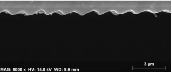
other hand, the discrepancy in experimental results can also be explained by possible measurement error (~ ±1%), or if we consider that the grooves profile of the replicated grating evaluated in experimental measurement for one sample were not exactly the same for another sample. If the grooves of PDMS mold are not perfectly full of photoresist, the grooves height of the replicated grating are not optimal as we can see an example on fig.8a (black sample). Indeed, real groove profile of replicated gratings can be deduced by fitting experimental measurements and theoretical simulations, completed by Scanning Electronic Microscope (SEM) measurements.
Figure 8a. SEM grooves profile of a replicated grating (2h30).
Figure 8b: SEM grooves profile, original grating.
Finally, during SVAIL process, groove height of the replicated grating increased progressively as a function of process duration (fig.2 & fig.6). Theoretical simulations indicated that the diffraction efficiency was ±37% @ 532nm, at initial step of the SVAIL process. Diffraction was due to only grooves profile of the PDMS mold. For intermediate steps of replication process, diffraction was realized by a combination of
PDMS mold and replicated grating in photoresist s1805 film. At the middle of the SVAIL process, the diffraction was due to PDMS mold and a replicated grating (with a trapezoidal shape) which grooves height was half of original grating or PDMS mold. At the final step, the PDMS mold grooves were full of photoresist, and the diffraction was realized by the combination of PDMS mold and the replicated grating which grooves height and shape were ideally similar to those of PDMS mold. And the diffraction efficiency was ±7 % at final step of SVAIL process. The strong slope at the first moment of SVAIL process (fig.5 or fig.5bis, [±600th second to ±1400th second]) characterizes the high activity of the replication process. In our case, under ±600th second, the solvent pressure is not enough to allow solvent propagation through the PDMS mold and to realize adequate replication. It was mainly the required time for the vapor solvent to completely fill the volume of the small glass box. Small concavity of the curve facing upwards observed at the end of strong slope, just after ±1400th second, could be explained by the allowable stress of the PDMS mold under gas pressure effect before system stabilization. It could be well understood with HOOKE’s law related to elastic material:
∆ℎ ℎ =
∆𝑃 𝐸 where Δh represents resultant height variation, h represents groove height of the PDMS mold,
ΔP represents pressure difference between top face and down face of the PDMS mold, E represents Young’s module constant of the elastic material.
The pressure variation is intimately related to variation grooves height of PDMS mold at its allowable stress edge and also to grooves height of replicated grating. And grooves height play a key role in diffraction efficiency. So system saturation was reached (after high activity of the replication process and also after small pressure variation) in our case at ±40th minute of the replication process. And diffraction efficiency measured in real time was constant for the remaining time of the SVAIL process. Moreover, the shape (allure, behavior) of the experimental curve is confirmed by that of the theoretical simulation (fig.5 & fig.4). Indeed, reference to theoretical simulations for various steps of the SVAIL process, we were able to indicate which moment to stop the replication process, obtaining a perfect replicated grating. Solvent vapor had two roles: maintain perfect contact between PDMS mold and coated substrate during the replication process, and curing effect on photoresist. Various durations of the SVAIL process were tested to see if there were a risk of cleaning the replicated grating (photoresist) for a long process (114h ~ 5days), but nothing changed because the diffraction efficiency measured at real time remained practically constant after a given duration (± 40minutes of the process in our case) until ~5days.
Finally, after diffraction efficiency experimental measurements of original diffraction grating and those replicated gratings for various durations, we observed that the replication was optimal when the diffraction efficiency measured in real time begun to be constant (± 40th minute), and stayed constant for the remaining duration.
CONCLUSION
We realized the replication of the diffraction grating by the SVAIL process with monitoring of diffraction efficiency in real time. Theoretical simulations of diffraction efficiency for various steps of SVAIL process compared to diffraction efficiency measurements realized in real time allowed to indicate the useful duration for grating replication by SVAIL process. And reference to experimental measurements of original and replicated gratings after demolding, the presented control way is enough to obtain a remarkable fidelity replication.
REFERENCES
[1] GONG Xiao GAO ChangYou Han L L et al. HAN LuLu, ZHOU Jing, Solvent-assisted polymer micro-molding, Chinese Science Bulletin, 54(13), July 2009.
[2] Zhao X M et al. Xia Y, Kim E., Complex optical surfaces formed by replica molding against elastomeric masters, Science, (273), 1996.
[3] Whitesides G M. Zhao X M, Xia Y, Fabrication of three-dimensional microstructures: Microtransfer molding, Adv Mater, (8), 1996.
[4] Whitesides G M Kumar. A. Features of gold having micrometer to centimeter dimensions can be formed through a combination of stamping with an elastomeric stamp and an alkanethiol 'ink' followed by chemical etching, Appl Phys Lett, (63), 1993.
[5] Whitesides G M Kim E, Xia. Y., Polymer microstructures formed by molding in capillaries, Nature, (376), 1995.
[6] Zhao X M et al Kim E, Xia Y., Solvent-assisted microcontact molding: A convenient method for fabricating three-dimensional structures on surfaces of polymers, Adv Mater, (9), 1997.
[7] Younan Xia Dong Qin and George M Whitesides, Soft lithography for micro and nanoscale patterning, nature protocols, 5(3), February 2010.
[8] Edward J. W. Crossland Piers Andrew Nicoleta E. Voicu, Sabine Ludwigs and Ullrich Steiner, Solvent-vapor-assisted imprint lithography, Adv. Mater., (19), 2007.
[9] M H Hon1 K L Lai1 and 3 I C Leu2, Pattern formation on polymer resist by solvent-assisted nanoimprinting with pdms mold as a solvent transport medium, Micromech. Microeng, (21), 2011.
[10] Ganesh K. Patil Rabibrata Mukherjee and Ashutosh Sharma, Solvent vapor-assisted imprinting of polymer films coated on curved surfaces with flexible pva stamps, American Chemical Society, February 2009.
[11] https://www.thorlabs.com/newgrouppage9.cfm?objectgroup_id=1123, visited April 18th, 2017.