HAL Id: inria-00569958
https://hal.inria.fr/inria-00569958
Submitted on 25 Feb 2011
HAL is a multi-disciplinary open access
archive for the deposit and dissemination of
sci-entific research documents, whether they are
pub-lished or not. The documents may come from
L’archive ouverte pluridisciplinaire HAL, est
destinée au dépôt et à la diffusion de documents
scientifiques de niveau recherche, publiés ou non,
émanant des établissements d’enseignement et de
Implicit Brushes for Stylized Line-based Rendering
Romain Vergne, David Vanderhaeghe, Jiazhou Chen, Pascal Barla, Xavier
Granier, Christophe Schlick
To cite this version:
Romain Vergne, David Vanderhaeghe, Jiazhou Chen, Pascal Barla, Xavier Granier, et al.. Implicit
Brushes for Stylized Line-based Rendering. Computer Graphics Forum, Wiley, 2011, 30 (2),
pp.513-522. �10.1111/j.1467-8659.2011.01892.x�. �inria-00569958�
EUROGRAPHICS 2011 / M. Chen and O. Deussen (Guest Editors)
Volume 30(2011), Number 2
Implicit Brushes for Stylized Line-based Rendering
Romain Vergne1 David Vanderhaeghe1,2 Jiazhou Chen1,3 Pascal Barla1 Xavier Granier1 Christophe Schlick1
1INRIA – Bordeaux University 2IRIT – Toulouse University 3State Key Lab of CAD&CG – Zhejiang University
Abstract
We introduce a new technique called Implicit Brushes to render animated 3D scenes with stylized lines in real-time with temporal coherence. An Implicit Brush is defined at a given pixel by the convolution of a brush footprint along a feature skeleton; the skeleton itself is obtained by locating surface features in the pixel neighborhood. Features are identified via image-space fitting techniques that not only extract their location, but also their profile, which permits to distinguish between sharp and smooth features. Profile parameters are then mapped to stylistic parameters such as brush orientation, size or opacity to give rise to a wide range of line-based styles.
Categories and Subject Descriptors (according to ACM CCS): I.3.3 [Computer Graphics]: Picture/Image Generation—Line and curve generation
1. Introduction
Line drawings have always been used for illustration pur-poses in most scientific and artistic domains. They have also played a fundamental role in the world of animation, mostly because they allow artists to depict the essence of charac-ters and objects with an economy of means. Unfortunately, even when artists restrict drawings to a few clean lines, hand-drawn animations require a considerable amount of skills and time. Computer-aided line-based rendering represents an efficient alternative: lines are automatically identified in animated 3D scenes, and drawn in a variety of styles. The challenge is then two-fold: extract a set of salient lines, and render them in a temporally coherent manner.
Most existing line-based rendering techniques consider salient lines as those that best depict the shape of 3D objects. According to the recent study of Cole et al. [CGL∗08], there
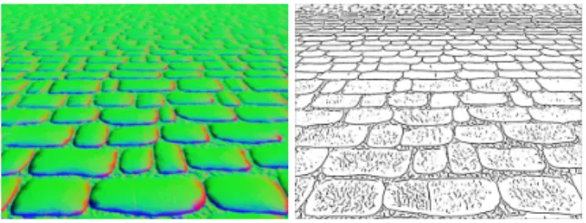
is no consensus among various line definitions. In particu-lar, lines drawn by human subjects do not always represent curvature extrema (ridges or valleys), but may also depict in-flections (transitions between convex and concave features). Moreover, lines from different subjects are hardly correlated, as illustrated in Figure1. It seems that the smoother and less pronounced a surface feature is, the less correlated lines will be, until eventually the feature is too smooth to be depicted by any line at all. The only exception occurs with occluding contours that depict infinitely sharp visibility discontinuities. These observations strongly suggest that on average, lines faithfully represent only these features that exhibit sharp-enough profiles. However, a surface feature profile evolves during animation, as the object gets closer or farther from
Figure 1: Correlation between hand-drawn lines. Lines drawn by a variety of subjects are accumulated, and either depict concavities (in orange), convexities (in blue) or inflec-tions. Correlation among subjects varies with feature profile sharpness (from top to bottom): lines have high precision at occluding contours, are spread around rounded features, and vaguely located or omitted around smooth features. the camera, and is rotated or deformed. We thus suggest that lines should be extracted dynamically at each frame, instead of being located onto object surfaces in a preprocess as done in previous work.
The second challenge of line-based rendering is to en-sure temporal coherence when lines are stylized. Most previ-ous techniques adopt a stroke-based approach to stylization:
c
2011 The Author(s)
Journal compilation c 2011 The Eurographics Association and Blackwell Publishing Ltd. Published by Blackwell Publishing, 9600 Garsington Road, Oxford OX4 2DQ, UK and 350 Main Street, Malden, MA 02148, USA.
they project extracted curves to screen space, parametrize them, and apply a texture along the parametrization to duce a brush stroke. However, surface features, once pro-jected onto the picture plane, are subject to various dis-tortion events during animation: they may either split and merge, or stretch and compress. The stroke-based approach thus raises two important issues: 1) surface features must be tracked accurately and each split or merge event must be handled carefully unless disturbing artifacts due to changes in parametrization will occur; and 2) stroke style must be updated during stretching or compression events unless styl-ization itself will be stretched or compressed. The simplest alternative for dealing with temporal coherence is to use image-space techniques. However, existing methods [ND04,
LMLH07] are severely restricted both in terms of depicted feature and stylistic choices.
In this paper, we introduce Implicit Brushes, an image-space line-based rendering technique that permits to depict most salient surface features with a wide variety of styles in a temporally coherent manner. The main contributions are the extension of previous image-space methods to more gen-eral definitions of image-space line features and a line ren-dering technique based on convolution that provides a richer range of styles. At each frame, our system identifies surface features located in the vicinity of each pixel, along with fea-ture profile information (Section3); it then produces a styl-ized line-based rendering via a convolution process that is only applied to pixels close to features with a sharp-enough profile (Section4). As a result, stylized lines emerge from the convolution process and dynamically appear or disap-pear to depict surface features with desired profiles. As with other image-space techniques, our approach does not require any temporal feature tracking for handling distortion events, since it relies on the temporal coherence of input data. This is to contrast with stroke-based approaches that introduce temporal artifacts due to parametrization changes.
This approach not only works in real-time with arbi-trary dynamic scenes (including deformable objects, even with changing topology), but its performance is indepen-dent of 3D scene complexity and it accommodates a number of surface feature definitions, including occluding contours, ridges, valleys and inflections. Thanks to its screen-space definition, it is easily incorporated in compositing pipelines, and works with videos. In terms of stylization abilities, we enrich our convolution-based method with coherent texture techniques inspired by watercolor rendering methods. The result is comparable to the brush tool of raster graphics soft-ware such as Photoshop or Gimp. This is to contrast with stroke-based methods, where texture is directly applied to the parametrization, which is similar to the vector graphics styles obtained with software such as Illustrator or Inkscape. 2. Previous work
The problem of identifying surface features as curves on 3D objects has received much attention in previous work.
Some authors focus on extracting intrinsic properties of ob-ject shape, such as ridges & valleys (e.g., [OBS04]) or in-flections (e.g., Demarcating Curves [KST08]). Although in-trinsic surface features are useful to depict purely geometric characteristics, they are not adapted to the goals of stylized rendering where the viewpoint and lighting have an influ-ence on the choice of drawn lines. Undoubtedly, the most im-portant of view-dependent features are occluding contours. They have been extended to Suggestive Contours [DFRS03] (and later Suggestive Highlights [DR07]) to include occlud-ing contours that occur with a minimal change of viewpoint. Apparent Ridges [JDA07] modify ridges & valleys to take into account foreshortening effects, showing an improved stability in feature extraction compared to Suggestive Con-tours. Alternative line definitions take light directions into account, as is the case of Photic Extremum Lines [XHT∗07]
and Laplacian Lines [ZHXC09].
Even if they introduce view- or light-dependent behav-iors, all these methods rely on a preprocess that performs differential geometry measurements in object space (except for occluding contours). Surface features are then extracted at runtime from these measurements as zero-crossings in a given direction. The main drawback of this approach is that it completely ignores surface feature profiles after these have been projected to screen-space. As a result, lines de-pict object features only at a single scale: surface details that would appear in close-up views are ignored, whereas lines appear cluttered when the object is zoomed out. More-over, deformable objects are not properly depicted since only their rest pose is taken into account for surface measure-ments. Techniques that precompute measurements at vari-ous object-space scales [NJLM06,CPJG09] or for a range of deformations [KNS∗
09] only partially solve the problem: they do not take projected surface features into account and cannot handle dynamic animations, while requiring user in-tervention and time- and memory-consuming preprocesses. In contrast, our system extracts new features along with their profile for each new frame, producing line drawings of fully dynamic animations in real-time.
The methods presented so far only produce simple lines. Stroke-based approaches have been introduced to con-fer varying thickness and textures to extracted lines, by means of a dedicated parametrization. Unfortunately, using a frame-by-frame parametrization leads to severe popping and flickering artifacts; hence static stylization techniques like the system of Grabli et al. [GTDS10] are not adapted to temporally coherent animation. Consequently, specific methods have been devised for the stylization of animated lines. Artistic Silhouettes [NM00] chain occluding contours into long stroke paths, and parametrize them to map a stroke texture. The WYSIWYG NPR system [KMM∗02] uses
syn-thesized stroke textures to ease the creation of novel styles that depict occluding contours and creases. Such methods are prone to many temporal artifacts though, which are due to the distortion events mentioned in Section 1.
Re-R. Vergne, D. Vanderhaeghe, J. Chen, P. Barla, X. Granier & C. Schlick / Implicit Brushes cent work has tried to address these important issues. The
Coherent Stylized Silhouettes of Kalnins et al. [KDMF03] track parametrizations from frame to frame and propose an optimization-based update rule that tries to limit arti-facts due to stretching and compression events. The method works in many practical cases, but may also lead to disturb-ing sliddisturb-ing artifacts. The Self-similar Lines ArtMaps of Bé-nard et al. [BCGF10] address the same issue by updating texture instead of parametrization, taking advantage of the self-similar nature of many line-based styles.
These stylization techniques deal fairly well with stretch-ing and compression, but they generally fail at dealstretch-ing prop-erly with splitting and merging, because such changes in line topology necessarily lead to sudden changes in parametriza-tion. Although this may not be too disturbing with occlud-ing contours where lines split or merge mostly around end-points, other surface features are more problematic. Imag-ine for instance a pair of parallel ridges that merge together as the object they belong to recedes in the background; in this case, there does not seem to be any natural approach to merge their parametrizations. Our alternative stylization technique avoids the use of parametrizations: it is based on a convolution process that permits a vast range of styles and deals naturally with distortion events.
A simpler solution to line-stylization is to make use of image filters. The pioneering technique of Saito and Taka-hashi [ST90] explored this idea. Their approach consists in applying simple filters to depth and normal maps in im-age space to extract occluding contours and creases. It has been adapted to the GPU by Niehaus and Döllner [ND04] using depth peeling for hidden lines and a wobbling ef-fect based on image-space noise for stylization. The method produces coherent line drawings and avoids line-clutter is-sues by working in screen-space. However, the choice of filter strongly limits both depicted features and line thick-ness, and the wobbling effect exhibits showerdoor-like ar-tifacts due to the use of a static screen-aligned noise func-tion. To our knowledge, the only filter-based technique that allows lines of controllable thickness is the method of Lee et al. [LMLH07]. It finds edges and ridges in shaded images of 3D objects using a local 2D fitting approach ap-plied to luminance. Although the method is limited to the depiction of luminance features with a simple line style, it shows that a fitting approach in screen-space is able to cap-ture and render dynamic feacap-tures in real-time. Our approach also makes use of a fitting technique and may thus be seen as a generalization of Lee et al.’s approach that works with various surface features and provides a richer range of styles. 3. Feature extraction
The study of Cole et al. [CGL∗08] has shown that although
occluding contours are expected to be depicted in virtually all line drawings, other surface features are not systemat-ically drawn. A simple use of occluding contours is not enough though. Regarding this issue, we make no attempt
at defining a new kind of surface feature in this paper. In-stead, our contribution consists in first providing a screen-space generic definition for most common surface features, then extending it to identify feature profiles (Section3.1). We then show how these generic surface features are ex-tracted in real-time using an implicit approach that works on the GPU (Section3.2).
3.1. Definitions
In this Section we define common surface features with a generic continuous screen-space formulation. Our choice of domain is motivated by the fact that even for rigid objects, surface features are subject to various distortions if one takes into account their projection in screen-space. For ease of no-tation, we consider in the following that 2refers to screen-space.
3.1.1. Feature Skeleton
Our first observation is that in most previous methods, fea-tures are identified as maxima of a differential geometry in-variant in a tangential direction. For instance, a ridge is a local maximum of maximal principal curvature in the max-imal principal direction. Similar features are obtained when the analysis is conducted in screen-space. We call the loci of such maxima the feature skeleton. Formally, it is defined by
S = ( s∈ 2 δh(s) δθ(s)= 0, δ2h(s) δθ(s)2 < 0 ) , (1)
where S ⊂ 2, h : 2→ is a C2height function, and θ : 2→ 2 is a C1 direction field. Both h and θ are easily instantiated to produce existing surface feature types.
First-order features are obtained by computing gradients in screen space. Occluding contours are well approximated by taking maxima of the depth gradient gdin its
correspond-ing direction. Surface Edges are obtained by takcorrespond-ing maxima of the surface gradient gn= (−nx/nz, −ny/nz) in its
cor-responding direction, where n = (nx, ny, nz) is the surface
normal expressed in screen-space. They are very similar to Suggestive Contours computed with the image-space algo-rithm of DeCarlo et al. [DFRS03], defined as minima of n.v, with v the view vector. Luminance edges are obtained by taking the maximum of the luminance gradient glin its
cor-responding direction. These features are similar to those of Lee et al. [LMLH07], and may be seen as a screen-space formulation of Photic Extremum Lines [XHT∗07].
Surface ridges and valleys are second-order features, and thus require to compute a curvature tensor H from which principal curvatures kmax and kmin and directions
tmax and tmin are extracted. The view-centered tensor of
Vergne et al. [VPB∗09] provides an appropriate
screen-space formulation. Surface ridges (resp. valleys) are ob-tained as maxima of kmax (resp. −kmin) in the tmax (resp.
tmin) direction. Contrary to Apparent Ridges [JDA07], tmax
and tminare orthogonal in our approach. c
2011 The Author(s)
Surface inflections are third-order features, and thus re-quire to compute a view-centered curvature-variation tensor Cfrom H, and extract a curvature gradient vmax from C.
Surface inflections are then obtained as maxima of vmaxin
its corresponding direction. They are similar to Demarcating Curves [KST08], but are defined in screen-space.
The set of surface features is summarized in Table1.
Names h θ
Occluding contours |gd| gd/|gd|
Surface Edges |gn| gn/|gn|
Luminance edges |gl| gl/|gl|
Surface ridges kmax tmax
Surface valleys −kmin tmin
Surface inflections |vmax| vmax/|vmax|
Table 1: List of common surface features. g symbols are used for gradients, k for principal curvatures, t for principal curvature directions and v for the curvature gradient.
3.1.2. Feature profile
An advantage of using Equation1is that we can now reason on abstract features without having to focus on a particular definition. As an example, we take the “ripple” function il-lustrated in Figure2. It is obvious from this example that the feature skeleton is not sufficient if one wants to convey differences between height field oscillations.
Our second observation is that all the required information to make this distinction is contained in the direction field. Indeed, classic differential geometry [dC76] tells us that for each non-singular point x of a direction field θ, there exists a unique curve cx(t) that passes through x and which tangent is
everywhere equal to θ. Such a curve is called a trajectory (or integral curve); a subset of trajectories is drawn as pale blue curves in Figure2. However, a trajectory may cross multiple times the feature skeleton S. To identify the unique feature profilecorresponding to a point s ∈ S, we clamp its trajec-tory to feature mimima (or singularities) on each side of s. This is illustrated in Figure2by the dark blue curve. The feature profile ps: (t−,t+) → at a point s ∈ S is defined
as the height function along the truncated trajectory: ps(t) = h ◦ cs(t), t ∈ (t−,t+), (2)
where t+(resp. t−) is the positive (resp. negative) parametric
location of either the closest minimum or nearest singularity. An interesting property of Equation2is that it also applies to any non-singular and non-minimal point x 6∈ S. Hence, because of the unicity of a trajectory, for each such point x lying in the span of a feature profile centered at s (the dark blue curve in Figure2), ps(t) and px(t) are equal up to a
parametric translation. In other words, a feature skeleton and profile can be obtained implicitly at x by analyzing a neigh-borhood along its trajectory. We make use of this property to extract feature skeleton and profiles in parallel at each pixel.
Figure 2:Simple ripple example: we show the height func-tion h(x) = cos(|x|)/(1 + 0.2|x|), a subset trajectories (in pale blue) of its directional fieldθ(x) = x/|x|, the corre-sponding feature skeletonS (in red), and a feature profile (in dark blue) that goes both through points x6∈ S and s ∈ S. 3.2. Implementation
The extraction of surface features as defined above for a con-tinuous screen-space domain are easily adapted to discrete screen-space. It makes their computation on modern graph-ics hardware particularly efficient. In our system, this is done in three stages: 1) we compute h(x) and θ(x) per pixel, using image processing operators; 2) we build a 1D neighborhood for each pixel x by following its trajectory; 3) we identify feature skeleton and profile along this neighborhood, using a fitting procedure.
3.2.1. Feature data
For first-order features, we compute gradients by applying a Sobel filter to the appropriate image buffer: the depth buffer for occluding contours, and the color buffer (averaging color channels) for luminance edges. The surface gradient gn
re-quired by surface edges is computed from normals, as ex-plained in Section3.1.1. For second-order features, we com-pute a view-centered curvature tensor by taking the gradient of gn[VPB∗09]. For third-order features, we apply a Sobel
filter to mean curvature H = tr(H) to compute vmax.
Apart for occluding contours that represent pure depth discontinuities, image filters may be applied to screen-space neighborhoods of varying size to capture coarser or finer surface features. However, care must be taken not to make such a neighborhood overlap an occluding contour, other-wise false surface features will emerge. To solve this prob-lem, we follow the approach of Vergne et al. [VPB∗09],
and apply an iterative anisotropic diffusion to surface or lu-minance gradients, using occluding contours as insulators. Each iteration corresponds to a filtering pass on the GPU, and the more iterations used, the coarser the features. This process not only smooths h but also θ, resulting in a smaller number of features as shown in the supplemental video.
Having identified h and θ per pixel for a particular choice of surface feature (see Table 1), we are only one step away from inspecting pixel neighborhoods: we must first locate feature singularities. Singularities of θ are approxi-mated with the mean angular variation in a 8-pixel
neigh-R. Vergne, D. Vanderhaeghe, J. Chen, P. Barla, X. Granier & C. Schlick / Implicit Brushes 1 p p s x
t
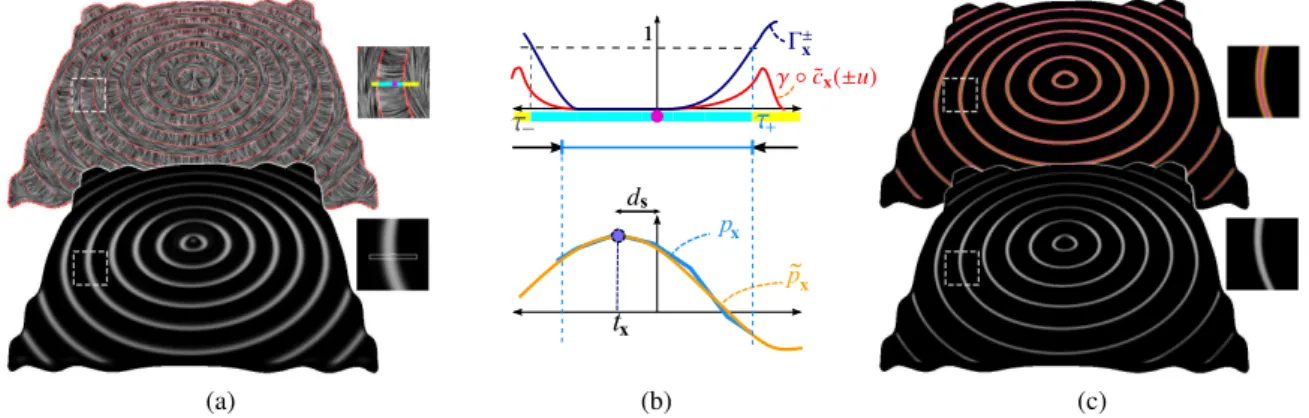
(a) (b) (c)Figure 3:Feature extraction: (a) Feature data consists of a direction fieldθ (here tmin, displayed on top using LIC with
singularities in red), and a height field h (here−kmin, displayed at bottom in gray-scales). (b) The trajectory ˜cx(t) is shrunk
by a factorτ+to stop at feature singularities (top); then profile data pxis fit using a cubic polynomial ˜px(bottom). (c) Profile
parameters such as the distance dsto the skeleton (top) and profile height ˜px(tx) (bottom) are spatially and temporally coherent.
borhood around each pixel: γθ(x) = 1 − Σ8i=1|θ(x).θi(x)|/8,
with θi(x) the orientation at neighboring pixel i.
Occlud-ing contours must also be considered as sOcclud-ingularities, since they delimit non-connex surface neighborhoods. They are approximated by γd(x) = ||gd(x)||. Feature singularities are
then identified by the union of directional and contour sin-gularities: γ(x) = max(γθ(x), γd(x)). Per-pixel feature data
is displayed in Figure 3-a, using Line Integral Convolu-tion [CL93] (LIC) for θ, which is a valid display since all our direction fields are defined modulo π. We show singular-ities in red; in this case they appear at places where principal curvatures are of equal magnitude (i.e., at inflection points). 3.2.2. Profile sampling
The second stage takes advantage of the observation made at the end of Section3.1: because each generic and non-singular pixel x belongs to a unique trajectory cx(t), we can
walk along cx(t) to find the feature profile it belongs to. In
practice, we consider a first-order Taylor expansion of cx(t)
(i.e., a linear neighborhood): ˜cx(t) = x +t θ(x). This
approx-imation is all the more valid for points in the vicinity of S where we have observed that trajectories are close to sim-ple lines. In our system, we measure px(t) along ˜cx(t) at
2k + 1 samples (henceforth named ti, i = −k..k) distributed
uniformly on each side of x (we use k = 4).
However, care must be taken not to go through a feature singularity. To deal with this issue, we take an approach sim-ilar to anisotropic diffusion: we shrink ˜cx(t) as soon as it
comes close to a feature singularity. To do that, we first ac-cumulate γ values on each side of x:
Γ±x(ti) = i
∑
k=0
γ ◦ ˜cx(t±k)
The neighborhood is then shrunk so that no feature singu-larity is crossed. This is done by identifying the location τ+
(resp. τ−) at which Γ+x (resp. Γ −
x) is greater than a
thresh-old Γmax(we use Γmax= 1), as illustrated at the top of
Fig-ure3(b). The shrinking factor is then taken to be the mini-mum of |τ−| and |τ+|. The shrunk neighborhood is
resam-pled using 2k + 1 uniformly distributed samples in order to have enough information for profile fitting.
3.2.3. Profile fitting
The goal of the third stage of analysis is to identify the lo-cation of a potential feature skeleton along the 1D neigh-borhood, with additional profile information. We do this by fitting an analytic profile function ˜px to profile data
mea-sured at tialong ˜cx(t). In practice, we take a least-squares
approach, minimizing a per-pixel profile energy on the GPU: E(x) =
k
∑
i=−k
(h ◦ ˜cx(ti) − ˜px(ti))2.
We use a cubic polynomial for the analytic profile function (see Figure3-b), since it has just enough degrees of free-dom to identify surrounding extrema: ˜px(t) = at3+ bt2+
ct+ d. Having a simple analytic expression for the pro-file at x allows us to identify characteristic propro-file prop-erties. The profile generally exhibits two extrema tα,β = (−b ±√b2− 3ac)/3a. The skeleton location txis easily
ob-tained by picking the one extrema for which the second-order derivative d2˜px(t)/dt2= 6at + 2b is positive (when
a single minimum is found, we ignore the pixel). Profile height and curvature are then simply given by ˜px(tx) and
d2˜px(tx)/dt2(since d ˜px(tx)/dt = 0).
Figure3(c) displays results of the fitting process: the per-pixel distance to the nearest feature skeleton ds = ||x −
˜cx(tx)|| is shown with a color gradient, and profile height
˜px(tx) is displayed in gray-scales. Observe how both
esti-mates are consistent across a feature profile, illustrating the spatial coherence of per-pixel fitting. Figure4compares the feature skeleton extracted with our approach to lines ob-tained with Apparent Ridges [JDA07] at different scales.
c
2011 The Author(s)
(a) (b)
Figure 4: Comparison with object-space features. (a) Sur-face features extracted in object-space lead to visual clut-ter (here Apparent Ridges & Valleys); (b) our screen-space ridges & valleys are devoid of this limitation.
Half of the ripple function has been corrupted with noise, which leads to visual clutter in the case of Apparent Ridges. In contrast, our screen-space approach produces clean line drawings, whereby the noise disappears for distant views. 4. Line stylization
Depicting dynamic surface features with stylized lines is not straightforward: since features are extracted at each frame, lines need to evolve constantly and coherently to adapt to various changes. Doing so with a stroke-based approach seems cumbersome due to the constantly occurring distor-tion events we mendistor-tioned in Secdistor-tion1. Our contribution is to provide an alternative stylization technique that is itself defined implicitly. It is based on a convolution approach that mimics the contact of a brush on canvas and easily takes feature profileinto account (Section4.1). We then show how our real-time GPU implementation permits the combination of different brushes and texture effects, and produces a rich variety of styles (Section4.2).
4.1. Feature-based convolution
Intuitively, our stylization technique consists in stamping brush footprints of various sizes, orientations, colors and opacities at points that are close-enough to a feature skeleton with a sharp-enough feature profile. The stylized lines that emerge from this process inherit the spatial and temporal co-herence of surface features. It may be seen as an adaptation of Convolution Surfaces [BS91] to the depiction of surface features. As in Section3, we first present the technique with a generic continuous screen-space formulation.
Formally, an Implicit Brush is a function I : 2 → [0, ∞)4that maps a point of the picture plane to a color. It
(a)
(b)
(c)
Figure 5:Weight functions. (a) withλp= 1 and σp= ε,
only thin binary lines are selected; (b) with λp
propor-tional to profile height, lines gently disappear with weak fea-tures; (c) withσpproportional to profile curvature, lines are
smudged around smooth features.
is defined as the convolution of a feature-based weight func-tion wp: 2→ [0,1] with a feature-based brush function
bp: 2→ [0,1]4:
I(y) = Z
2wp(x) bp(y − x) dx. (3)
At each point of the image, I measures the accumulation of weighted footprint contributions for each color channel (including opacity). We remap its values to the [0,1]4range via a homogeneous scaling among color channels as classi-cally done in color tone mapping techniques [Sch94]. The main difference between Implicit Brushes and Convolution Surfaces is that both the weight and brush functions depend on feature profile, as indicated by the p subscript.
The weight function implicitly controls which points of the picture plane are close-enough to a sharp-enough feature. Line-like appearance is ensured by requiring the function to be monotonically decreasing. We use a Gaussian function in our approach: wp(x) = λpexp−d 2 s/2σ 2 p,
where ds is the distance to the nearest feature skeleton as
before, and λpand σpare the feature-based weight peak and
standard deviation respectively. Various choices for λpand
σpmay be made and we show three typical combinations in
Figure5, using a small disc footprint. Other combinations are left to user investigations.
The brush function controls how a user-selected brush footprint is applied to local feature data. We separate the
R. Vergne, D. Vanderhaeghe, J. Chen, P. Barla, X. Granier & C. Schlick / Implicit Brushes
(a)
(b)
(c)
Figure 6:Brush functions. By varying fpand Tp, we obtain
different styles correlated to feature profile properties. (a) Tp orient the footprint along the skeleton; (b) Tpscale the
footprint proportionally to profile height; (c) fpget its color
from the shaded 3D object at the skeleton position.
footprint from its positioning to allow more user control: bp(u) = fp◦ Tp(u)
where fpis a color footprint function defined in its own
para-metric space, and Tpis a transform that maps a point of the
picture plane to this parametric space. We use a similarity transform for Tpin our system. Making both functions
de-pend on feature properties permits to correlate style with sur-face features: Tpmay orient, scale or move the footprint
ac-cording to profile properties, while fpmay change the color
of the footprint, as shown in Figure6, where we have used the weight function of Figure5-a. Other combinations of fp
and Tpare left to user investigations.
Although line style may be strongly correlated to surface features thanks to the choice of weight and brush functions, it is nonetheless independent of the feature extraction pro-cess. This is to contrast with previous image-based tech-niques where extraction and stylization are part of a single process. This is illustrated in Figure7where we compare Implicit Brushes with the method of Lee et al. [LMLH07] with identical input data and similar styles. With the method of Lee et al., only opacity can be modulated after the 2D fitting process, and one must modify feature extraction to control line thickness. As a result, rendering of thin lines re-quires the identification of small features, which raises noise issues. With our technique, feature extraction is independent
(a)
(b)
(c)
Figure 7: Comparison with Lee et al. [LMLH07]. Ren-dering luminance valleys from (a) with the method of Lee et al. (b) produces satisfying results for thick-enough lines (left) but raises noise issues with thin lines (right). Opacity thresholds are chosen to obtain the cleanest pos-sible lines. With Implicit Brushes (c), feature extraction and line stylization are controlled independently, which produces clean line renderings for any choice of line thickness.
of stylization choices, which allows us to create clean ren-derings even with thin lines.
For aesthetic reasons, it is also necessary to incorporate variations that are not related to any feature property. Exam-ples include the addition of canvas texture, line interruptions, color variation or wobbling effects. In our system, such ef-fects are obtained by modulating each component of Equa-tion3with its own noise texture, noted η in the following. For instance, the canvas texture effect is obtained by mul-tiplying I directly by η; line interruptions are produced by multiplying λpby η; color variations are obtained by
mod-ulating the color of fp; and wobbling effects are created by
modulating parameters of Tpwith η.
c
2011 The Author(s)
(a) (b) (c) (d) Figure 8:A few line styles. Each row shows (a) a footprint in its parametric space, (b) applied to a simple curve, (c) with a noise-based small perturbation ; or (d) with a more pro-nounced perturbation. From top to bottom, we perturb brush position, orientation, size, color and add canvas texture.
4.2. Practical applications
Our prototype system provides a rudimentary brush design interface. A sample of common brush styles is shown in Fig-ure8: users choose a footprint texture or function (Figure8 -a), adjust basic weight and brush parameters (Figure8-b), and add noise-based perturbation (Figure8-c-d), observing stylistic variations in real-time. However, as in watercolor rendering techniques, the use of a static screen-aligned noise texture will likely produce sliding artifacts. As of now, there are two known solutions to this issue, both incorporated in our system: textures are either advected off-line using optic flow [BNTS07], or combined at multiple scales to create a fractal texture in real-time [BCGF10].
The main advantage of our convolution-based technique over more complex stylization solutions is that it is fully dy-namic: style is entirely controlled by the choice of weight and brush functions, and the algorithm does not require any pre-process, nor does it need to inspect past or future frames, yet ensuring temporal coherence. The method is thus ideally adapted to an implementation on the GPU. Our prototype implementation works in real-time on a NVidia G-480, with a single feature displayed at a time. In practice, we first com-pute per-pixel weight values and brush transform parameters in a fragment shader, taking extracted feature data as input. An Implicit Brush image is then obtained by rendering one textured quad per pixel with additive blending enabled. Each quad opacity is simply determined by the weight value at its corresponding pixel; it is rotated, scaled and translated ac-cording to brush transform parameters; and it is filled using either a bitmap footprint texture or a simple procedural func-tion. The tone mapping operator is applied in a final pass.
Our stylization technique targets applications of various sorts. First, it is well adapted to scientific illustration. Styl-ized lines are strongly correlated to surface features, as shown in Figure9where many small valleys of an engraved stone are depicted with lines where thickness depends on profile curvature. The method deals equally well with dy-namic phenomena like fluids, as seen in the supplemental video. Second, it provides an attractive line-based
render-ing solution for video games. It works with deformable 3D models such as the animated horse of Figure10and natu-rally depicts features found in normal maps as seen in Fig-ure11. Third, the method can be used as a building block for the stylization of videos. If normal and depth images are available (e.g., exported from a 3D rendering application), then multiple feature types may be depicted in a single image by applying our technique on each type of feature and com-positing them. This is illustrated in Figure12, which shows a fly sequence over a terrain model with ridges, valleys and occluding contours rendered in different ways. Our method may also be applied to a standard video, as seen in the water drop sequence of Figure13where stylized lines are either drawn alone or overlayed on top of original images. In this case, we use luminance edges and make only use of direc-tional singularities since occluding contours are unavailable. 5. Discussion and future work
We have presented two implicit techniques for surface fea-ture extraction and line stylization that, when used in com-bination, permit to create coherent stylized line-based ren-derings of dynamic 3D scenes in real-time. We avoid vi-sual clutter thanks to a screen-space definition that ex-tracts generic features which profile is relevant at a user-chosen scale. Our stylization technique produces lines that are strongly correlated to depicted feature profiles. It is also naturally coherent, without requiring preprocessing or track-ing: this is because features are extracted from temporally coherent normal and depth buffers, and we preserve such co-herence through fitting and convolution.
The performance of our system is mainly dependent on fill-rate: it varies with image resolution, the number of anisotropic diffusion iterations, and footprint size. For exam-ple, using a NVidia G-480, it runs at 82 fps at a resolution of 1024 × 768 with a footprint of radius 10 pixels. Perfor-mances drop down with increasing iterations: it runs at 56, 40 and 31 fps for 10, 20 and 30 iterations respectively.
Our feature extraction technique works for a range of sur-face feature types, including edges, ridges, valleys, occlud-ing contours and inflections. However, the choice of feature has an influence on a feature profile extent: indeed, with fea-ture definitions of increasing order, more singularities occur, which leads to more profile clamping on average. Another limitation of our approach is that it ignores junctions, pre-cisely because they are located at directional singularities. An exciting direction of future work would thus be to find a novel feature definition that limits the number of singular points, while easing the identification of junctions. Our sur-face features often exhibit natural behaviors when objects re-cede in the background. This is due to our screen-space algo-rithm that implicitly merges features based on their distance in the picture plane. The quality of rendered lines for distant objects is sensitive to aliasing though: flickering artifacts oc-cur if no anti-aliasing technique is used. Moreover, such a
R. Vergne, D. Vanderhaeghe, J. Chen, P. Barla, X. Granier & C. Schlick / Implicit Brushes
Figure 9:Rendering a carved stone. Both engraved symbols and details of this stone correspond to surface valleys, although with different profiles. We convey this distinction by varying disk footprint size according to profile curvature.
Figure 10:A deformable 3D model. Frames of an animated 3D horse model rendered with shaded surface valleys. systematic simplification may not always be adapted. For fa-miliar objects, one may want to preserve important features (e.g., around the eyes) in multiple views; for structured ob-jects such as grid- or wave-like patterns, simplification may not be robust to small viewpoint variations. We would like to investigate object-space semantic simplification techniques in future work to complement our approach.
Our stylization technique produces temporally coherent lines from dynamic 3D scenes in a variety of styles. In com-parison, other methods are either limited in terms of styl-ization abilities [ND04,LMLH07], since they only provide thickness control; or they are prone to temporal artifacts even on static objects [KDMF03,BCGF10], mainly with split or merge events. The flexibility of our approach comes at a price though: user control is less direct with Implicit Brushes than with stroke-based techniques. For instance, perturba-tions are produced via a global screen-space texture; and stylized lines automatically end at feature end-points based on the choice of weight function. In other words, there is no simple solution for applying a stroke texture along a line. Al-though it is a limitation that prevents accurate local control of line style, it may also be seen as an advantage for the ap-plications we target in this paper: style is designed once and for all and applied either in real-time for dynamic systems, or as a batch process for compositing pipelines. However, a more direct and local control in both space and time might be required, for special effects applications for instance. In such cases, our stylization technique is not adapted, but our feature extraction technique is still relevant. A promising av-enue of future work would be to extend the WYSIWYG ap-proach [KMM∗
02] to depict dynamic surface features.
Figure 11: Rendering normal maps. Since our method works from normal buffers, it deals naturally with normal-mapped objects, here with surface valleys.
Acknowledgments
We would like to thank Forrester Cole for providing hand-drawn line data used in Figure1, and the Aim@Shape li-brary for 3D models of Figures5,6and10. This work has been sponsored by the Animare (ANR-08-JCJC-0078-01) and SeARCH (ANR-09-CORD-019) projects, and the IN-RIA postdoctoral program.
References
[BCGF10] BÉNARDP., COLEF., GOLOVINSKIYA., FINKEL
-STEINA.: Self-similar texture for coherent line stylization. In
Proc. NPAR(2010), ACM, pp. 91–97.
[BNTS07] BOUSSEAUA., NEYRETF., THOLLOTJ., SALESIN
D.: Video watercolorization using bidirectional texture advec-tion. ACM TOG (Proc. SIGGRAPH) 26, 3 (2007).
[BS91] BLOOMENTHALJ., SHOEMAKEK.: Convolution sur-faces. In Proc. SIGGRAPH (1991), vol. 25, ACM, pp. 251–256. [CGL∗08] COLE F., GOLOVINSKIY A., LIMPAECHER A.,
BARROS H. S., FINKELSTEIN A., FUNKHOUSER T., RUSINKIEWICZ S.: Where Do People Draw Lines? ACM
TOG (Proc. SIGGRAPH 2008) 27, 3 (2008), 1–11.
[CL93] CABRALB., LEEDOML. C.: Imaging vector fields using line integral convolution. In Proc. SIGGRAPH (1993), ACM, pp. 263–270.
[CPJG09] CIPRIANOG., PHILLIPS JR. G. N., GLEICHERM.:
Multi-scale surface descriptors. IEEE TVCG 15, 6 (2009), 1201– 1208.
[dC76] DOCARMOM. P.: Differential Geometry of Curves and
Surfaces. Prentice-Hall, Englewood Cliffs, NJ, 1976.
[DFRS03] DECARLOD., FINKELSTEINA., RUSINKIEWICZS., SANTELLAA.: Suggestive Contours for Conveying Shape. ACM
TOG (Proc. SIGGRAPH) 22, 3 (2003), 848–855.
c
2011 The Author(s)
Figure 12:Composited features. A 3D terrain model rendered with two different styles for ridges and valleys. Surface features are simplified automatically at different scales, and the corresponding stylized lines are merged coherently.
Figure 13:A stylized video. Frames of a water drop video where luminance edges are depicted with lines of varying thickness, either drawn in black (top), or drawn in white over the original image (bottom), both with a disk footprint.
[DR07] DECARLOD., RUSINKIEWICZS.: Highlight lines for conveying shape. In Proc. NPAR (2007), ACM, pp. 63–70. [GTDS10] GRABLI S., TURQUIN E., DURAND F., SILLION
F. X.: Programmable rendering of line drawing from 3d scenes.
ACM TOG 29, 2 (2010), 1–20.
[JDA07] JUDD T., DURAND F., ADELSON E. H.: Apparent
Ridges for Line Drawing. ACM TOG (Proc. SIGGRAPH) 26, 3 (2007), 19.
[KDMF03] KALNINSR. D., DAVIDSONP. L., MARKOSIANL., FINKELSTEIN A.: Coherent stylized silhouettes. ACM TOG
(Proc. SIGGRAPH) 22, 3 (2003), 856–861.
[KMM∗02] KALNINS R. D., MARKOSIAN L., MEIER B. J.,
KOWALSKIM. A., LEEJ. C., DAVIDSON P. L., WEBBM., HUGHESJ. F., FINKELSTEINA.: Wysiwyg npr: drawing strokes directly on 3d models. ACM TOG (Proc. SIGGRAPH) 21, 3 (2002), 755–762.
[KNS∗09] KALOGERAKISE., NOWROUZEZAHRAID., SIMARI
P., MCCRAEJ., HERTZMANNA., SINGHK.: Data-driven cur-vature for real-time line drawing of dynamic scene. ACM TOG
28, 1 (2009).
[KST08] KOLOMENKINM., SHIMSHONII., TALA.: Demarcat-ing Curves for Shape Illustration. ACM TOG (Proc. SIGGRAPH
Asia) 27, 5 (2008), 1–9.
[LMLH07] LEE Y., MARKOSIANL., LEE S., HUGHES J. F.: Line drawings via abstracted shading. ACM TOG (Proc.
SIG-GRAPH) 26, 3 (2007), 18.
[ND04] NIENHAUSM., DÖLLNERJ.: Blueprints: illustrating
ar-chitecture and technical parts using hardware-accelerated non-photorealistic rendering. In Proc. GI (2004), pp. 49–56. [NJLM06] NIA., JEONGK., LEES., MARKOSIANL.:
Multi-scale line drawings from 3d meshes. In Proc. I3D (New York, NY, USA, 2006), ACM, pp. 133–137.
[NM00] NORTHRUPJ. D., MARKOSIANL.: Artistic silhouettes:
a hybrid approach. In Proc. NPAR (2000), ACM, pp. 31–37. [OBS04] OHTAKEY., BELYAEVA., SEIDELH.-P.: Ridge-valley
lines on meshes via implicit surface fitting. ACM TOG (Proc.
SIGGRAPH) 3, 23 (2004), 609–612.
[Sch94] SCHLICKC.: Quantization techniques for visualization of high dynamic range pictures. In Proc. EGSR (1994), Springer-Verlag, pp. 7–20.
[ST90] SAITOT., TAKAHASHIT.: Comprehensible rendering of 3-d shapes. vol. 24, ACM, pp. 197–206.
[VPB∗09] VERGNER., PACANOWSKIR., BARLAP., GRANIER
X., SCHLICKC.: Light warping for enhanced surface depiction.
ACM TOG (Proc. SIGGRAPH) 28, 3 (2009).
[XHT∗07] XIEX., HEY., TIANF., SEAHH.-S., GUX., QIN
H.: An effective illustrative visualization framework based on photic extremum lines. IEEE TVCG 13, 6 (2007), 1328–1335. [ZHXC09] ZHANG L., HEY., XIEX., CHENW.: Laplacian
Lines for Real Time Shape Illustration. In Proc. I3D (2009), ACM.


![Figure 7: Comparison with Lee et al. [LMLH07]. Ren- Ren-dering luminance valleys from (a) with the method of Lee et al](https://thumb-eu.123doks.com/thumbv2/123doknet/14427018.514418/8.892.136.408.127.481/figure-comparison-lee-lmlh-dering-luminance-valleys-method.webp)