Science Arts & Métiers (SAM)
is an open access repository that collects the work of Arts et Métiers Institute of
Technology researchers and makes it freely available over the web where possible.
This is an author-deposited version published in: https://sam.ensam.eu Handle ID: .http://hdl.handle.net/10985/8256
To cite this version :
Ivan IORDANOFF, Daniel ILIESCU, Jean-Luc CHARLES, Jérôme NEAUPORT - Discrete Element Method, a Tool to Investigate Complex Material Behaviour in Material Forming - In: NUMIFORM 2010: Proceedings of the 10th International Conference on Numerical Methods in Industrial Forming Processes Dedicated to Professor O. C. Zienkiewicz (1921–2009), Korea, Republic Of, 2010-06 - NUMIFORM 2010: Proceedings of the 10th International Conference on Numerical Methods in Industrial Forming Processes(1921–2009) - 2010
Any correspondence concerning this service should be sent to the repository Administrator : [email protected]
Discrete Element Method, a Tool to Investigate Complex
Material Behaviour in Material Forming
Ivan Iordanoff
a, Daniel Iliescu
a, Jean Luc Charles
aand Jérome Néauport
b,
aLAMEFIP, ARTS et METIERS PARISTECH, Esplanade des arts et métiers, 33440 Talence, France. bCEA CESTA, 33114, Le Barp
Abstract. Discrete Model is based on the description of the physical state (velocity, position, temperature, magnetic moment, electric potential ..) of a large number of discrete elements that form the media to be studied. It is not based on a continuous description of the media. Then, it is particularly well adapted to describe media evolution driven by discontinuous phenomena:
- multi fracturation problems like abrasion process and composite machining, - description of multi fracturation followed by debris flow like wear study
Recently, the use of discrete model has been widened to face problem encountered with complex rheological behavior and/or multi-physical behavior. Multi-physical problems face complex mathematical formulation because of the mixing of different families of differential equations when continuous approach is chosen. With the discrete model, each particle has a physical state and state evolution is due to local physical particle interaction: it is often much simple to write. Some attempt to study complex multi-physical problems has been recently presented:
- thermal study of a contact and how dissymmetry appears in an apparently symmetrical problem, - study of Friction Stir Welding.
This work outlines how discrete element model can be a useful tool in the simulation of material forming. Example is given on abrasion process and machining of composite.
Keywords: Discrete Element Model, Abrasion, Composite Machining, tribology
PACS: 02.70.ns
INTRODUCTION
Discrete element method has been widely developed for rheological study of true discrete materials like sand, powder and granular materials. In the past ten years, their fields of applications have been extended to heterogeneous materials like concrete, biological materials or foams. Their ability to simulate multi body behavior is used for problems where:
- A great number of dissociated elements must be taken into account, - A great number of default is encountered
The main recent fields of applications are multi-fractures problems, where detached elements must be taken into account (wear in tribology [2], avalanches in geophysic, milling, grinding …). In these cases, Continuum mechanic approach faces difficulties due to the development of discontinuity surfaces (cracks, multi body contacts) . DEM is a alternative because it is based on a discrete description of the material.
In material forming or cutting, the contact zone between the tool and the working piece is often very difficult to analyze because:
- The affected area has little dimension,
- High mechanical, rheological, thermal gradient are involved,
- Physical phenomena are highly dynamic.
In these cases, continuum approach faces difficulties to determine the accurate thermo mechanical behavior law as a macroscopic level. Discrete approach proposes to introduce behavior law as a set of particle interactions laws. It is shown in this paper how rather simple particle interaction laws conduce to complex macroscopical behaviors.
DEM Approach is now greatly applied to describe tribological problems : to analyze the contact behavior Godet developed the third body concept [3]. This included a description of the formation and movement of fragmented CREDIT LINE (BELOW) TO BE INSERTED ON THE FIRST PAGE OF EACH PAPER
EXCEPT THE PAPER ON PP. 837 TO 840
CP1252, NUMIFORM 2010, Proceedings of the10th International Conference
edited by F. Barlat, Y. H. Moon, and M.G. Lee © 2010 American Institute of Physics 978-0-7354-0800-5/10/$30.00
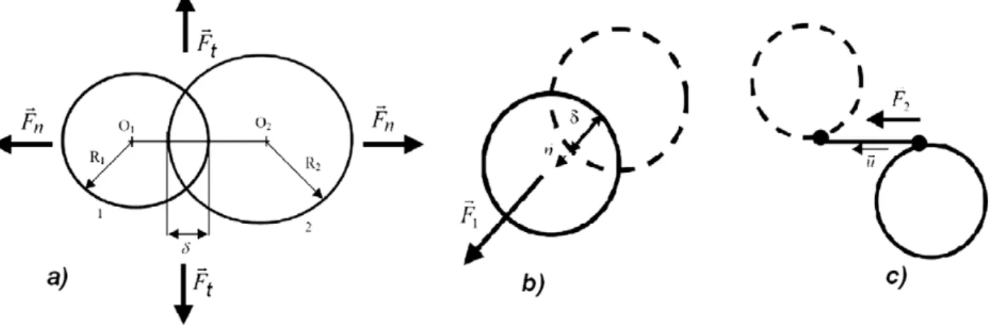
FIGURE 1. Contact and solid joint force calculation.
particles in the interface region. To study the behavior of the third body inside and outside the contact, Berthier proposed [4] the tribological circuit which allows the study of mass transfers inside the contact. Based on this tribological circuit and coupling Discrete Element models (DEM) to experimental, but simplified, wear studies, Fillot et al [5] proposed a set of equations that allows a qualitative modeling of wear as a mass balance in the contact area. Iordanoff et al. [6] showed how abrasion process can be studied as a particular and controlled wear process.
This paper first presents the Discrete Element Methods developed in the special case of material forming. Then, two examples are given to illustrate how this numerical tool can be used to study local properties in material forming: investigation of Sub Surface Damage in abrasion process and effect of fiber orientation on composite machining.
NUMERICAL TOOL
The method described is based on smooth particle dynamic Method. The material is considered as a set of discrete particles that moves under a force field. The forces are contact forces to simulate multi body interactions and joint forces to simulate a solid made of discrete elements. Particle movements are calculated using an explicit algorithm to integrate the dynamic Newton law. A thermal model can be couple with the mechanical one. Both Conduction through contact and thermal energy source due to mechanical dissipation are taken into account. The two next paragraphs briefly described the mechanical part. More details can be found in references [2]. The thermal part is not used in this paper but widely describe in [7].
Mechanical Model
The particle interaction laws define the micro mechanical properties of the media. They are divided into contact forces and joint forces. Every particle is subjected to contact force. This force acts only when two particles
geometrically interact. Two adjacent particles belonging to the same solid are linked by a solid joint that acts under traction, compression and shear displacement.
Contact Force
Contact force is divided into three parts: repulsion, adhesion (both are energy conservative) and energy dissipation. Geometrical interaction
allows the force calculation (Fig.1).Repulsion is represented by a linear spring, that stiffness is K. Repulsive force Fr is:
*
K
Adhesion has been simplified to a constant
:
a
F
(2)The energy dissipation in the contact is due to the damping force written as:
.
*
2
ijd
K
M
F
(3)where
is the damping coefficient (<1),
the impact speed, and Mij the equivalent mass of the contact.The sum of the interaction forces is:
2
.
.
.
ij d a r contactF
F
F
K
K
M
F
(4)Solid Joint Law
To simulate a material, solid link between particles is created. This link can be considered as elastic whose ends are fixed on the each particle surface. The forces are not calculated only on the basis of the particles centers distance but also according to the distance between grip points. Two types of interactions are considered: a normal force F1
and a tangential force F2. The normal and tangential interactions are linear springs with different stiffness (Fig. 1). F1
has the same expression than Fcontact, but this time
can take negative values. The tangential force F2 is :u
l
k
F
2
.
.
(5)Where k is the tangential stiffness, l the tangential relative displacement and
u
the tangential vectorParticle Detachment
In the present study, it is assumed that a link breaks only under traction state: when the link is under traction and when the link equivalent force reaches a yield value Fy, the link is broken. The link equivalent force used in this
paper is: 2 2 2 1
3F
F
F
eq
(6)Numerical Model
A dynamic integrating algorithm must be used. A Verlet Algorithm is chosen to obtain accelerations, velocities and positions at each time step.
APPLICATION
In this section, two example show the ability of Discrete Element Model to describe complex behavior faces by forming processes :
- Abrasion process, where the description of multi-fracturation and flow of abrasive and wear particle between the tool and the piece is a challenge for the models.
- Composite machining where the coupling between fiber cracks, matrix cracks and fiber-matrix interface cracks is complex to investigate
Upper
wall
Lower wall
Degradable
First body
Imposed velocity
Periodical boundaries
x
y
z
Abrasive particles
Upperwall
Lower wall
Degradable
First body
Imposed velocity
Periodical boundaries
x
y
z
Abrasive particles
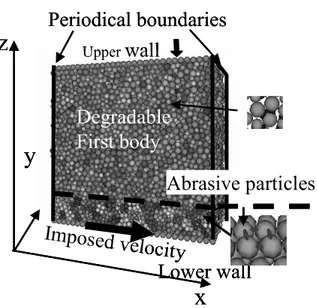
FIGURE2Simulated domain.
Sub Surface Damages Study in Abrasion Process
The studied material is silica. According to Fig. 2, the upper first body (Silica piece to be surfaced) is constituted by spheres linked together by elastic solid joints. This first body is linked to the upper wall. A normal load is applied to the upper wall which is free to move along axis z. The lower first body (tool) is simply defined as a lower rigid all made of adjacent spheres. A constant velocity along x is applied to the lower wall. The abrasive particles are plates composed by 4 adjacent spheres linked by an elastic non breakable solid link.
Simulated Domain
The effect of abrasive size and abrasive quantity through the contact are studied. Abrasive size is the same than silica particles (*1) or twice silica particles (*2). Table 1 summarizes the studied cases.
Results
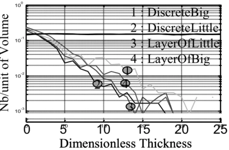
Calculations are carried out till a certain amount of silica particle is removed from the silica volume, by the effect of broken links. The fixed amount is 150 particles. Broken links through the volume are plotted in terms of the distance from the surface. Curves Fig. 3 show the results. The thickness is divided by particle mean radius.
5 10 15 20 25 30 10-3 10-2 10-1 100
0
5
10
15
20
25
Nb
/u
nit
of
Vo
lu
m
e
Dimensionless Thickness
1 : DiscreteBig
2 : DiscreteLittle
3 : LayerOfLittle
4 : LayerOfBig
3
2
4
1
5 10 15 20 25 30 10-3 10-2 10-1 1000
5
10
15
20
25
Nb
/u
nit
of
Vo
lu
m
e
Dimensionless Thickness
1 : DiscreteBig
2 : DiscreteLittle
3 : LayerOfLittle
4 : LayerOfBig
3
2
4
1
FIGURE 3. Number of broken joint through the thickness.
The number of broken joints decreases exponentially with the depth. It greatly depends on abrasive geometrical properties and quantity. A little number of big abrasive particles creates more residual cracks in the material. These results are qualitatively in accordance with experimental results [9]. This first simple study demonstrates how discrete element simulations have the ability to simulate the formation of a great number of cracks and the link between sub surface damage and abrasive properties.
Composite Machining
Composite Generation
To model the carbon fiber, two rows of particles are considered. This allows taking into account the fibers bending. Depending of the fiber orientation, one column of particles for the fiber orientation at 90°, or one line of particles for the fiber orientation at 0°, or one diagonal of particles for fiber orientation at 45° and 45° are built. The distance between two neighboring fibers, which represents the matrix, is chosen to obtain fiber volume fraction equals to 60%).
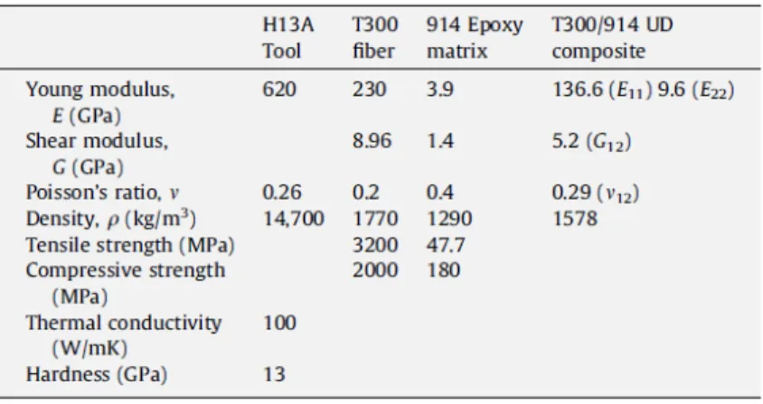
Modeling Parameters
The behavior of the composite is characterized by a set of macroscopic parameters due to the behavior of fiber and matrix components. The properties of H13A carbide tools (WC-Co6%) and of the composite (fiber and matrix) used for discrete element simulations are given in Table2. The difficulty is then to deduce the micro data from the macro data given by continuum mechnanics. The method here consists in the definition of a characteristic diameter for the fibers and the matrix. Then Young modulus is linked to stiffness, and yield stresses to yield forces thanks to the relationship :
Force
stress
.D
2. Dimensionless yield forces and stiffness are given in table 3. The dimensionless stiffness of the tool is set to 1.Table 1. Abrasive layer definition.
Nb of Abra. plates abrasive size
Case „DiscreteBig‟ 6 *2
Case „LayerOfLittle‟ 39 *1
Case „DiscreteLittle‟ 19 *1
FIGURE 4. 90° oriented fibers (d) and 0° oriented fibers (e). Table 2. material properties of composite material and tool material.
Table 3. dimensionless parameters for DEM Simulation.
Results
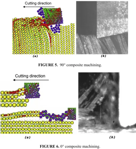
For a fiber orientation at 90°, the material removal is initiated by the bending of fiber bundles ahead of the tool; a mode I opening through the workpiece along the fiber/matrix interface is then observed. Damages are represented by the detachment of fibers and the multicracking of the composite surface. High speed video images of the chip formation confirm these phenomena (Fig. 5). After shearing, fibers elastically return to their initial position and rub on the tool clearance face which produces wear. During machining of a 90° oriented composite, the compression zone located below the tool leads to significant in-depth cracks in the composite. The contact distribution and connections forces can be observed in Fig. 5a. In red compression forces are shown and in green tensile forces. The images provided by the discrete element simulation allow pointing out high compression, bending and delamination of the fiber.
FIGURE 5. 90° composite machining.
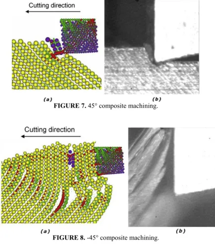
FIGURE 6. 0° composite machining.
For a 0° fiber orientation, chips are first broken by a mode I cracking with rupture along the fiber/matrix interface combined with a mode II cracking in the direction of the tool feed (Fig. 6). The chip separation occurs after buckling rupture of the fibers in a perpendicular direction to their axis, due to the pressure applied by the tool. When cutting a layer at 0°, the tool produces delamination and fiber pulling of large dimensions as a wood chip. Machining with that fiber orientation produces large fragmented debris. High speed video images of the chip formation reveal a decohesion of fiber bundles which bend and break by buckling (Fig. 6b). The images provided by the discrete element simulation allow pointing out high compression, bending and delamination of the fiber bundles (Fig. 6a).
For 45° fiber orientations, the chip formation mechanism consists of a fiber stretching and a fiber shearing by the cutting edge. The chip is then formed by fiber/matrix interface shearing to the free surface and ejection of the chip (Fig. 7). Failure occurs in a direction perpendicular to the fiber axis (at -45°). During the cutting of fibers oriented at 45°, the tool can directly cut the fiber. 45° oriented fibers machining gives very small chips. High speed video images of the chip formation reveal a small bending and a significant compression of the fibers by the tool (Fig. 7b). After chip ejection, the fibers elastically return to their position and rub on the tool clearance face, which produces abrasive wear. Debris can also be found between the tool clearance face and the workpiece, and can contribute to wear. This orientation of the fibers leads to the highest tool wear. The particles of the workpiece which have lost all connections with the neighboring particles change color from yellow to violet (Fig. 7a).
During the cutting of fibers oriented at -45°, the fibers significantly bend over and break by pulling out (Fig. 8). High speed video images of the chip formation reveal a very important bending of fibers that remain compact (in bundles) up to rupture (Fig. 8b). The discrete element simulation shows more explicitly the bending of fibers and the rupture which occurs in a direction perpendicular to the fibers axis (Fig. 8a). The damages which propagate into the workpiece are noticeable. The fibers slide on the cutting edge, bend and then torn up. Shearing of fibers occurs in a
FIGURE 7. 45° composite machining.
FIGURE 8. -45° composite machining.
plane significantly lower than the theoretical machined surface. In this configuration the cutting surface is very irregular and the tool wear is low.
These four simulation allow to reproduce qualitatively the main phenomena observed experimentally. The quality of the obtained surface and the effect of composite machining on the tool wear are two important data concerning composite machining. It is very difficult to simulate and predict these data with conventional continuous approaches. In this case, some work has to be done to obtain quantitative results but DEM shows its ability to simulate such complex machining process.
CONCLUSIONS
This paper demonstrates how discrete element model is able to simulate complex behaviors due to material machining. It is particularly well adapted for the simulation of brittle material machining where complex set of fracturations are observed. In this paper, microscopic data are deduced from material properties linked to continuum mechanics. Results are qualitatively good but some work has to be carried out to obtained quantitative results for prediction of cracks, surface topology and/or tool wear. How to determine properly micro mechanical law is a great challenge because special experiments, adapted to these determinations must be imagined. They cannot be deduced systematically from continuum mechanic data if one can used all the possibility of such approach.
REFERENCES
1. GDR MIDI, On Dense Granular Flows, Eur. Phys. J. E 14, 341-365, 2004
2. Fillot, Iordanoff, Berthier, “Modelling third body flows with a discrete element method-a tool for understanding wear with adhesive particles”, Tribology International, 40, Issue 6, June 2007, Pages 973-981
4. Berthier, Y., 1995, “Maurice Godet‟s Third Body”, 22nd Leeds-Lyon Symposium on Tribology, Tribology series, 31, pp.
21-30.
5. N.Fillot, I. Iordanoff, Y. Berthier : “Wear modelling and the Third Body concept”, Wear, Elsevier, 2007, 262 n°7-8, pp. 949-957.
6. I. Iordanoff, A. Battentier, J. Neauport, J.L. Charles, A discrete element model to investigate sub-surface damage due to surface polishing. Tribology International 41 (11), pp. 957-964, 2008
7. D. Richard, I. Iordanoff, M. Renouf, Y. Berthier, Thermal Study of the Dry Sliding Contact With Third Body Presence. Journal of Tribology, DOI: 10.1115/1.2913540
8. Vargas, W. L., McCarthy, J. J., 2001, “Heat Conduction in Granular Materials,” AIChE Journal, 47, pp. 1052-10
9. T. Sutatwala, L. Wong, P. Miler, M. D. Feity, J. Menapace, R. Steele, P. Davis and D. Walmer, "Sub-surface mechanical damage distribution during grinding of fused silica", J. Non Crys. Sol. 352 (2006) 5601-5617